Visible-light plasmonic photocatalyst anchored on titanate nanotubes: a novel nanohybrid with synergistic effects of adsorption and degradation
Yuxin
Tang†
a,
Zhelong
Jiang†
ab,
Qiuling
Tay
a,
Jiyang
Deng
a,
Yuekun
Lai
ac,
Dangguo
Gong
a,
Zhili
Dong
*a and
Zhong
Chen
*a
aSchool of Materials Science and Engineering, Nanyang Technological University, 50 Nanyang Avenue, Singapore 639798. E-mail: aszchen@ntu.edu.sg; zldong@ntu.edu.sg; Fax: +65 6790 9081; Tel: +65 6790 4256 Tel: +65 6790 6727
bC.N. Yang Scholars Programme, Nanyang Technological University, 60 Nanyang Drive, SBS-02n-45, Singapore 637551
cPhysikalisches Institute and Center for Nanotechnology (CeNTech), Westfälische Wilhelms-Universität, Münster, Münster D-48149, Germany
First published on 7th August 2012
Abstract
A nanohybrid plasmonic photocatalyst, comprising Ag-AgX (X = Cl, Br, I) nanoparticles anchored on titanate nanotubes, was fabricated via a silver ion incorporation process followed by hydrogen halide injection and light-irradiation. The Ag-AgX-titanate nanotubes (Ag-AgX-TNT) hybrid with a high surface area could synergistically adsorb and degrade methylene blue (MB) under visible light, viz., the titanate nanotubes adsorb MB onto their surfaces, which aids the degradation of MB by Ag-AgX nanoparticles. The excellent degradation performance of Ag-AgX under visible light originated from its localized surface plasmonic resonance effect. Therefore, this integrated silver halides/titanate hybrid can efficiently degrade MB dye, and shows good potential for waste water treatment utilizing solar irradiation.
1 Introduction
Photocatalysis has attractive potential applications in the conversion of solar energy into chemical energy (e.g., hydrocarbon/hydrogen fuel) as well as the degradation of toxic water/air pollutants.1–7 Many semiconductors have been explored and examined in detail for their functionalities in photocatalysis. Among them, TiO2 has been the most promising candidate for photocatalysis applications because of its photostability, natural abundance, and nontoxicity.8–11 However, there are some drawbacks associated with TiO2. The activity of TiO2 is confined to UV-light irradiation, and the adsorptive properties of TiO2 are not ideal either.12 Since photocatalytic reactions take place on or near the catalyst surface, surface adsorption is critical for efficient interfacial charge transfer to and from the target molecules. Recently, titanate nanostructures, derived from TiO2 materials under alkaline conditions,13,14 have been identified as superior adsorbents for the removal of organic dyes and heavy metal ions.14–17 From the photocatalytic standpoint, it would be highly beneficial to combine the high catalytic activity of photocatalysts with the superior adsorptive properties of titanate, especially for the removal of high concentration organic compounds. Without good adsorption of organic molecules, a highly concentrated dye solution cannot be efficiently degraded by photocatalysis, because the organic dye will strongly absorb light, therefore rendering the solution impenetrable to light. As such, the semiconductor photocatalyst in the solution cannot efficiently interact with the photon energy, and this is termed as the light shielding effect of colored dyes. Because of this, developing efficient photocatalysts with good adsorptive ability is crucial to promoting degradation efficiency in highly concentrated organic dye solutions.Following this concept, exploring efficient and stable photocatalysts under visible light is an important issue, and plasmonic photocatalysts are promising materials to meet this requirement.18,19 In recent years, a series of highly efficient plasmonic silver@silver halide photocatalysts have been developed for photocatalytic decomposition of organics under ultraviolet (UV)/visible-light illumination,20–29 and excellent photoactivity and stability of silver@silver halides has been reported.30–37 For example, Huang's group20,30 recently developed a series of Ag@AgX (X = Cl, Br, I) for organic molecule degradation under visible light, and they found that their degradation rate was several times higher than that using nitrogen-doped TiO2. Hu et al.21 demonstrated that the introduction of Ag/AgBr in TiO2 enhanced the photocatalytic activity for the destruction of azo dyes and bacteria under visible light. It has been demonstrated that the exposed facets have an important effect on the enhanced photocatalytic activities of Ag3PO4,38 AgCl39 and AgBr40,41 photocatalysts. Besides controlling the exposed facets, novel approaches have also been developed to fabricate nanoscale silver halide materials or their hybrid systems to improve the photocatalytic performance, taking advantage of efficient electron–hole separation at the hybrid interfaces. Ye's group22 and Sun24 demonstrated the formation of uniformly distributed Ag or Au nanoparticles (NPs) on AgCl nanowires via in situ oxidation of Ag nanowires in Fe3+ solution with PVP. Yu et al.23 and Li' group33 demonstrated that Ag/AgCl or AgBr NPs could be immobilized on TiO2 nanotubes. The nanocomposite photocatalyst exhibited high visible-light photocatalytic activity. New Ag@AgX/graphene nanocomposites were designed via a water/oil approach by Liu's group,31,42 which showed good photocatalytic activity under sunlight. In our previous work,26,43 silver halide NPs were introduced onto a honeycomb-like titanate nanowire thin film by an in situ ion exchange reaction. However, both the silver halides and titanate nanowire thin films show limited adsorption of the methyl orange dye due to their low surface area and weak electrostatic interactions with dye molecules. To overcome this deficiency, we need to develop a photocatalyst with a large surface area and good adsorptive properties. Herein, we demonstrate a novel nanohybrid plasmonic photocatalyst (Ag-AgX-TNT) for the efficient removal of high concentration cationic organic dye by a synergistic effect of adsorption and degradation. Methylene blue (MB) was selected as a target molecule on the consideration of electrostatic interactions between the positively charged MB molecules and the negatively charged protonated titanate nanotubes (P-TNT) in aqueous solution, which facilitates the capping of MB on the outer surface of P-TNT by adsorption.17 P-TNT powder is chosen for its large surface area (284.6 m2 g−1) compared with titanate nanowires or nanosheets,44 which offers more anchoring sites for AgX photocatalysts on its surface. After the introduction of the AgCl nanoparticles on the P-TNT materials, the samples maintained a high surface area around 242.2 m2 g−1, whereas that of bulk or commercial Ag-AgCl particles is much lower (10 m2 g−1 or less). The resultant high surface area nanohybrid photocatalysts showed remarkable adsorption and excellent photocatalytic activity for the removal of high concentration MB dye.
2 Experimental
2.1 Preparation of P-TNT via a hydrothermal method
The P-TNT can be synthesized by a hydrothermal method in alkaline conditions. Commercially acquired anatase TiO2 powder (∼2.0 g) and an aqueous solution of NaOH (10 M, 75 mL) were placed into a Teflon-lined autoclave. The mixture was stirred to form a milk-like suspension, sealed and hydrothermally treated at 130 °C for 48 h. The synthesized sodium titanate precipitates were separated by centrifugation and washed with deionized water until a pH value near 8 was reached. Then proton-exchange was conducted 3 times in 0.1 M HNO3 solution to yield the P-TNT.2.2 Preparation of hybrid Ag-AgX-TNT powder photocatalyst
![[thin space (1/6-em)]](https://www.rsc.org/images/entities/char_2009.gif) :
:![[thin space (1/6-em)]](https://www.rsc.org/images/entities/char_2009.gif) 3 volumetric ratio) solution using a solar simulator 300 W Xe lamp (HAL-320, Asahi Spectra Co., Ltd.) at an intensity of ca. 100 mW cm−2 for 30 min to yield Ag-AgX-TNT powder. AgCl-T-Z was photoreduced in the same manner, yielding Ag-AgCl-T-Z.
3 volumetric ratio) solution using a solar simulator 300 W Xe lamp (HAL-320, Asahi Spectra Co., Ltd.) at an intensity of ca. 100 mW cm−2 for 30 min to yield Ag-AgX-TNT powder. AgCl-T-Z was photoreduced in the same manner, yielding Ag-AgCl-T-Z.
2.3 Sample characterization
The morphology of the as-synthesized powders after reaction was investigated by a field emission scanning electron microscope (FESEM, JEOL JSM-7600F). A transmission electron microscope (TEM, JEOL JEM-2100F) operating at 200 kV was used to characterize the detailed nanostructures. Energy dispersive X-ray (EDX) analysis was carried out in conjunction with the TEM and FESEM studies. Nitrogen adsorption/desorption isotherms were measured at 77 K using ASAP2000 adsorption apparatus from Micromeritics. The samples were degassed at 373 K for 4 h under vacuum before analysis. A Bruker D8 Powder X-ray diffractometer (XRD) with Cu-Kα radiation was used for phase identification. The optical absorption spectra of samples were measured on a Shimadzu 3600 UV-vis-NIR spectrometer in diffuse reflectance mode over the range 300–800 nm against a BaSO4 standard. The zeta potential of the suspensions was determined by Zetaplus (Brookhaven Instruments Corp., USA). Suspensions were prepared by dispersing titanate nanotubes (0.01 vol.%) in deionized water both in the absence and presence of the dispersant at various pH values.2.4 Photocatalytic degradation of methylene blue dye
Methylene blue (MB) was chosen as the target compound for the photocatalytic degradation experiments. The batch experiments were conducted in a beaker with an aqueous solution of MB (50 mg L−1, 20 mL) at a stirring rate of 400 rpm throughout the test at room temperature. The photocatalyst loading for these tests was 1.0 mg mL−1. The light-irradiation was performed using a solar simulator 300 W Xe lamp (HAL-320, Asahi Spectra Co., Ltd.) with a super cold filter (YSC0750), which provides visible light ranging from 400 nm to 700 nm. The light intensity was around 95 mW cm−2. MB concentrations at different time intervals were determined quantitatively by the absorption peak generated using a UV-2501 spectrophotometer.3 Results and discussion
The synthesis of these nano-hybrid plasmonic photocatalysts used titanate nanotubes as the precursor template, and involved a silver ion incorporation process followed by hydrogen halide injection and light-irradiation, as schematically depicted in Fig. 1a. As can be implied from the FESEM and TEM images in Fig. 1b–d, the multi-walled titanate nanotubes had a cylindrical shape with a hollow cavity along the length, providing a large surface area (compared with titanate nanowires or nanosheets) for molecular adsorption and AgX anchoring. The nanotubes were a few hundred nanometres long with a diameter of around 10 nm (Fig. 1c–d). The nitrogen adsorption isotherm of the starting material P-TNT is displayed in Fig. 2a, revealing a specific surface area of 284.6 m2 g−1 from Brunauer–Emmett–Teller (BET) analysis, and a major pore diameter distribution around 4 nm (inset in Fig. 2a) from Barrett–Joyner–Halenda (BJH) analysis, that corresponded to the hollow interior of the nanotube. The zeta potential experiment in Fig. 2b indicates that the surface charge of titanate nanotubes under the neutral condition was negative, which was suitable for the cationic organic dye adsorption.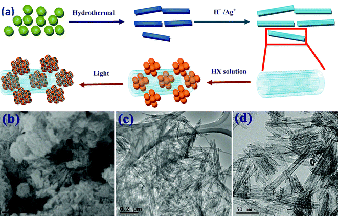 | ||
| Fig. 1 (a) The schematic of the preparation process of Ag-AgX-TNT. (b) FESEM image of P-TNT. (c) Low and (d) high magnification TEM images of P-TNT. | ||
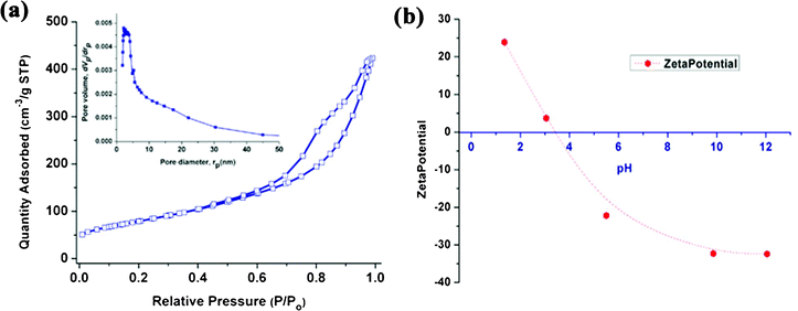 | ||
| Fig. 2 (a) N2 sorption isotherms and (b) zeta potential of titanate nanotubes in water at different pH values. | ||
After anchoring AgCl NPs onto the P-TNT following the synthetic scheme in Fig. 1a, the resultant AgCl-TNT material had a comparable specific surface area of 242.2 m2 g−1. Moreover, a typical FESEM image of AgCl-TNT (Fig. 3a) shows that the porous AgCl-TNT nanocomposite exhibited a microscale sponge-like morphology. Although the morphology of the nanotube is not obvious under SEM since the surface was decorated with numerous AgCl NPs, the TEM observation clearly shows AgCl-TNT clusters with AgCl particles in island form (Fig. 3b–c). Compared with pure P-TNT (Fig. 1c–d), successful formation of AgCl NPs on the titanate nanotube surface is evident. The scanning transmission electron microscopy (STEM)-EDX mapping results in Fig. 3d–f support the above conclusion. As shown in Fig. 3d, e and f, Ti, Ag, and Cl elements were uniformly distributed, and the deposition of AgCl NPs was well spread over the titanate nanotube surfaces after the HCl injection. Some metallic Ag clusters (circled in Fig. 3e) were detected because of the decomposition of AgCl under high-energy electron beam bombardment during TEM analysis.
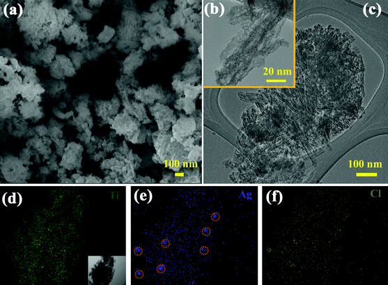 | ||
| Fig. 3 (a) FESEM and (b, c) TEM images of the AgCl-TNT; (d, e, f) STEM-EDX mapping of Ti, Ag, and Cl elements, respectively of the AgCl-TNT sample. The inset in Fig. 1d is the corresponding FESEM image of AgCl-TNT used for elemental mapping. | ||
To further characterize the crystal structure of the materials at different preparation stages, X-ray diffraction (XRD) was carried out, and the results are shown in Fig. 4A–B. As illustrated in Fig. 1a, titania were first hydrothermally treated in alkaline solution at 130 °C, followed by washing with deionized water, generating sodium titanate nanotubes (Na-TNT). For titanate materials, layers of two-dimensional [TiO6] octahedral sheets are intercalated by sodium or hydrogen ions, which can be exchanged with other cations.45 The formed Na-TNT was then placed in HNO3 solution and subsequently in AgNO3 solution to obtain the P-TNT and Ag-TNT respectively. As shown in Fig. 4A-a, the broad peaks at 2θ = 24.6°, 28.5° and 48.3° of P-TNT correspond well to the (110), (310) and (020) planes of orthorhombic H2Ti2O5·H2O (JCPDS No. 47-0124). After the silver ion exchange (Fig. 4A-b), no impurity phases such as Ag2O were observed, which suggests that the Ag+ ions are successfully incorporated into the titanate lattice. The XRD pattern in Fig. 4A-c indicates the presence of cubic phase AgCl (JCPDS file: 31-1238) on the surface of titanate nanotubes after rapid injection of HCl solutions into the Ag-TNT suspension. In addition to HCl, other HX solutions can also be injected into the Ag-TNT suspension, giving rise to AgBr or AgI decorated titanate nanotubes. The validation of this is provided in Fig. 4A-d and Fig. 4A-e, confirming the successful anchoring of face-centered cubic AgBr (JCPDS file: 06-0438) and hexagonal β-AgI (JCPDS file: 09-0374) onto the surface of P-TNT respectively. Finally, as illustrated in Fig. 4B, light-irradiation of AgX-TNT partially reduced the interstitial silver ions in AgX to metallic silver clusters, producing hybrid-structured materials Ag-AgX-TNT. The (111) peaks corresponding to the Ag NPs were detected in the Ag-AgCl-TNT and Ag-AgBr-TNT samples (Fig. 4B-a and Fig. 4B-b), whereas almost no signals from Ag were observed for the Ag-AgI-TNT sample (Fig. 4B-c). This can be attributed to the higher stability of AgI-TNT under light illumination, which is consistent with the results of previous work.27,46 The overall morphology of AgBr-TNT and AgI-TNT is depicted in Fig. 4C and Fig. 4D respectively, and the same microscale sponge-like morphology as AgCl-TNT (Fig. 3a) is observed, suggesting morphological similarity between this series of silver-halide decorated titanate nanotube materials.
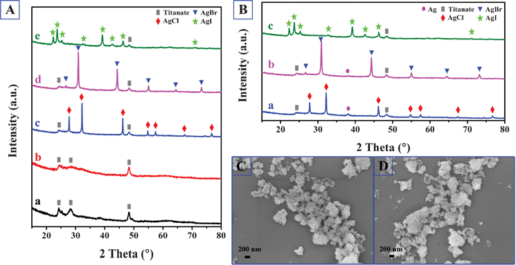 | ||
| Fig. 4 (A) XRD patterns of the AgX decorated titanate nanotubes and their precursors: a. P-TNT; b. Ag-TNT; c. AgCl-TNT; d. AgBr-TNT; e. AgI-TNT. (B) XRD patterns of the dual-functional plasmonic photocatalysts: a. Ag-AgCl-TNT; b. Ag-AgBr-TNT; c. Ag-AgI-TNT. (C) FESEM image of AgBr-TNT. (D) FESEM image of AgI-TNT. | ||
The UV-vis absorption spectra of the as-prepared samples are shown in Fig. 5. It is observed that the P-TNT showed a strong absorption below a wavelength of 400 nm, mainly attributed to the optical band gap of titanate materials. The absorption spectrum was slightly red-shifted when the P-TNT sample was exchanged with Ag+ ions (Ag-TNT). When the Ag-TNT had reacted with HX, AgX NPs were formed on the TNT surface, and the colour changed from light yellow (Ag-TNT) to white grey, pale yellow and yellow for AgCl, AgBr and AgI respectively, as shown in the digital photos in the inset of Fig. 5. AgCl and AgBr were reported to have a direct band gap of 5.15 eV (indirect band gap 3.25 eV) and 4.25 eV (indirect band gap 2.6 eV) respectively while AgI has a lower direct band gap of 2.8 eV.43 Thus, the AgI-TNT sample showed a stronger visible light absorption compared with AgCl-TNT and AgBr-TNT. After the light illumination, Ag NPs will be partially reduced from AgX samples. From the UV-vis spectra (Fig. 5), the Ag-AgCl-TNT and Ag-AgBr-TNT samples showed a broad plasmonic resonance peak of silver NPs around 440 nm, while the Ag-AgI-TNT sample showed a similar absorption spectrum to that of the AgI-TNT sample, due to far fewer Ag NPs formed under the same processing conditions; this observation is consistent with the XRD result (Fig. 4B). The digital photos corresponding to the UV-vis spectra also confirm the formation of Ag NPs on the AgX-TNT samples.
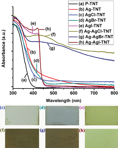 | ||
| Fig. 5 The UV-vis absorption spectra of (a) P-TNT; (b) Ag-TNT; (c) AgCl-TNT; (d) AgBr-TNT; (e) AgI-TNT; (f) Ag-AgCl-TNT; (g) Ag-AgBr-TNT; (h) Ag-AgI-TNT. The insets are the corresponding digital photos of the samples. | ||
The ability of Ag-AgX-TNT to degrade organic waste, arising from the synergistic effect of adsorption and photocatalytic mineralization, was demonstrated in this study by the elimination of methylene blue (MB) dye. To differentiate the role between adsorption and photocatalysis, a comparison was made using Ag-AgCl-TNT and bulk Ag-AgCl samples under dark conditions and under visible light illumination. When Ag-AgCl-TNT was added to MB solution in the dark, adsorption took place and the concentration of MB decreased dramatically in the first 30 min, and then subsequently slowed down (Fig. 6a). This was due to fast electrostatic interaction between the positively charged MB and the negatively charged titanate adsorbent. Fig. 6b shows the changes in the optical spectrum of the MB solution when bulk Ag-AgCl was added under the illumination of visible light. Due to limited adsorption of the bulk form of Ag-AgCl (which is illustrated in Fig. 6d), the concentration change of MB is expected to be induced mostly by photocatalysis. As shown in Fig. 6b, the optical absorption of the solution decreased continuously as illumination time increased. Moreover, a slight shift in the absorption peak positions was present. Such shifts have been observed in other systems as well and they correspond to the N-demethylation of MB and formation of intermediate products of MB breakdown.12,47,48 According to the above experiments, it was found that the TNT and Ag-AgCl nanoparticles can display different functionalities for the MB dye removal. To prove this concept, the nanohybrid Ag-AgCl-TNT was employed to remove the MB dye via simultaneous adsorption (from TNT) and photocatalytic degradation (from Ag-AgCl) under visible light. As evidenced from Fig. 6c, when these two functionalities work in conjunction, the characteristics of both adsorption and photocatalysis were observed simultaneously, resulting in improved efficiency of MB removal. According to previous work,27,43 the photogenerated electrons from Ag nanoparticles can transfer to the conduction band of silver halides and then they will be trapped by O2 in the solution to form superoxide ions (O2−˙) and reactive hydrogen peroxide species (H2O2) radicals. The holes escaped from recombination possess a strong oxidation power, which can directly degrade the organic compounds. Therefore, the O2−˙, H2O2 radicals and holes contribute to the destruction of the organic dye via chemical reaction. The same experiments were carried out for Ag-AgBr-TNT and Ag-AgI-TNT as well, and similarly more effective MB removal phenomena were observed. Moreover, it was found that the XRD spectra of the Ag-AgX-TNT samples after degradation experiments (not shown here) are similar to their as-prepared states.
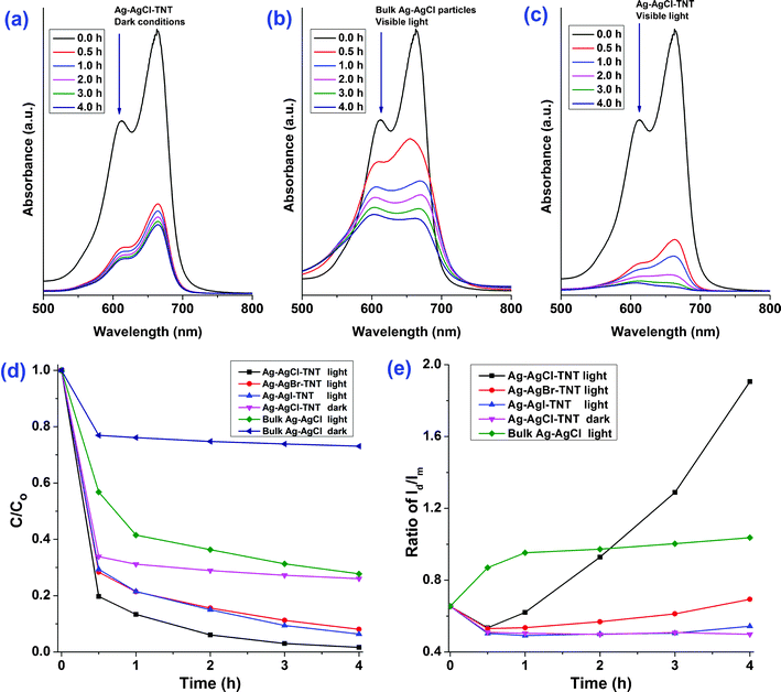 | ||
| Fig. 6 Methylene blue (MB) aqueous solution absorption spectra after treatment using (a) Ag-AgCl-TNT under dark conditions, (b) bulk Ag-AgCl particles under visible light, and (c) Ag-AgCl-TNT under visible light for different durations. (d) Adsorption and visible light degradation performance of different silver/silver halide based photocatalysts/conditions for MB removal. C0 (50 mg L−1) and C are the initial and final concentrations of the MB solution after adsorption and visible-light-illunimation, respectively, as determined by the MB absorption peak at 663 nm. (e) Changes of the intensity ratio of the two MB absorption peaks (612 nm (Id) and 663 nm (Im)) under different photocatalysts/conditions. | ||
Close scrutiny of the initial MB absorption spectrum (Fig. 6a–c, 0 h) reveals two absorption peaks at 612 nm and 663 nm, corresponding to dimers and monomers of MB respectively.49,50 Under adsorption and/or photocatalysis, both the monomer peak intensity (Im) and dimer peak intensity (Id) decreased (Fig. 6a–c). The time courses of MB removal on various photocatalysts were calculated according to changes in Im, and the resulting MB monomer removal profiles are shown in Fig. 6d. Moreover, the time courses of MB dimer to monomer peak intensity ratio (Id/Im) on various photocatalysts are shown in Fig. 6e. From this figure, when only adsorption took place (Ag-AgCl-TNT dark), Id/Im decreased with time, indicating that a higher percentage of MB dimer was adsorbed than MB monomer. In contrast, when mostly photocatalysis took place (bulk Ag-AgCl light), Id/Im increased continuously with time, indicating that a higher percentage of MB monomer was decomposed under photocatalysis than MB dimer. A similar observation that Ag-AgCl material has a higher degradation rate towards the MB monomer compared with the MB dimer was also reported in literature.50 Since the change of Id/Im ratios has different correlations with the adsorption and photocatalysis process, it can be used to differentiate the dominant effect during MB removal. As illustrated in Fig. 6e, all the three Ag-AgX-TNT samples showed a decrease in Id/Im for the first 30 min, but a gradual increase afterwards. The decrease of Id/Im implies the initial dominance of adsorption, and it is consistent with adsorption characteristics described previously. The later rebound in Id/Im ratio indicates that as time progressed, the contribution from photocatalysis became more and more overwhelming. Such behaviour, rather than monotonic evolution, further supports the presence of adsorption and photocatalysis dual-functionalities of the nano-hybrid Ag-AgX-TNT materials.
As can be seen from Fig. 6d, all the three Ag-AgX-TNT had higher MB removal ability in the light than in the dark, indicating the existence of photocatalytic breakdown of MB. The photocatalytic efficiency of the Ag-AgX-TNT was much higher than that of the bulk Ag-AgCl, even if the loading of active components (Ag-AgX) in the hybrid structured Ag-AgX-TNT was far less than in the bulk Ag-AgCl material. In one of our experiments, the weight percentage of Ag-AgCl, Ag-AgBr, Ag-AgI on Ag-AgX-TNT were around 15%, 14%, 12% respectively from the EDX measurements, among which the Ag-AgCl-TNT was found to possess the highest MB removal rate. This is believed to be due to its higher Ag0 loading (Fig. 4B) and stronger SPR absorption in the visible region (Fig. 5). Ag-AgBr-TNT and Ag-AgI-TNT were found to have a slightly lower MB removal rate. The above results demonstrate that, by anchoring a plasmonic photocatalyst onto a more effective adsorption substrate such as TNT to form a nano-hybrid dual-functional material system, the synergistic effect of adsorption and degradation led to more efficient removal of the high concentration organic dye.
To further verify the above observation that the effectiveness of rapid bleaching of the MB solution strongly depends on the phase structure, size and morphology of the adsorbent substrate, and the synergistic effect between adsorption and photodegradation, a special experiment was designed to mitigate the adsorption function by thermal treatment. When the photocatalysts were calcined, the TNT phase gradually disappeared. Correspondingly, the MB removal performance decreased. It can be observed from the XRD patterns (Fig. 7A) that when the AgCl-TNT material was thermally calcined, the titanate phase could still be retained at 250 °C, but a titanate-to-anatase phase transformation took place at calcination temperatures greater than 350 °C, and the higher the calcination temperature, the greater the completeness of this transformation. The ability of all these calcined AgCl-T-Z samples to be photoreduced to produce silver NPs is well-demonstrated from the XRD patterns of the Ag-AgCl-T-Z samples in Fig. 7B. Along with this titanate-to-anatase phase transformation, a nanotube-to-nanoparticle morphological transformation took place as well during calcination. As can be seen from Fig. 8a–c, when titanate reorganized to anatase above 350 °C, the nanotubular morphology could be no longer preserved and clusters of individual nanoparticles formed. Despite these phase and morphological changes, all Ag-AgCl-Z samples maintained strong plasmonic absorption of visible light (Fig. 8d).
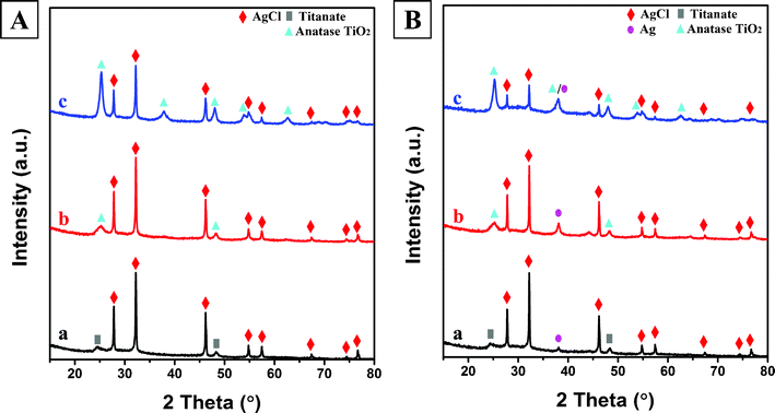 | ||
| Fig. 7 (A) X-ray diffraction patterns of calcined AgCl-T-Z samples: a. AgCl-T-250; b. AgCl-T-350; c. AgCl-T-450. (B) X-ray diffraction patterns of calcined and photoreduced Ag-AgCl-T-Z plasmonic photocatalysts: a. Ag-AgCl-T-250; b. Ag-AgCl-T-350; c. Ag-AgCl-T-450. | ||
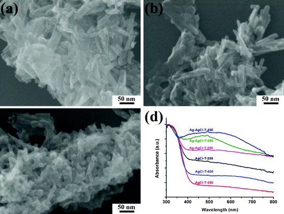 | ||
| Fig. 8 Typical FESEM images of (a) AgCl-T-250, (b) AgCl-T-350, and (c) AgCl-T-450. (d) Normalized UV-visible diffuse reflectance spectra of the calcined AgCl-T-Z samples and the calcined and photoreduced Ag-AgCl-T-Z samples. | ||
The performance of the Ag-AgCl-T-Z samples, along with that of the original Ag-AgCl-TNT, towards MB dye adsorption and visible light photocatalysis is demonstrated in Fig. 9. After treatment at 250 °C, the Ag-AgCl-T-250 showed very little change in MB removal rate compared with Ag-AgCl-TNT. However, after treatment at 350 °C and 450 °C, both adsorbance capability and photocatalytic degradation were severely reduced. Because the excellent plasmonic visible light absorption capability was maintained for the calcined samples (Fig. 8d), this poor MB removal performance should be attributed to the morphology and phase transformation from titanate nanotubes to anatase particles, which degrades their MB dye adsorption capability. In addition, lower adsorption on the annealed sample makes the MB solution highly colored, so the light shielding effect from the highly concentrated MB dye led to reduced interaction of the light-active material with photons, rendering the photocatalytic degradation inferior. Therefore, maintaining titanate nanotubes in this dual-functionality photocatalyst is of significant importance in achieving its highly efficient removal capability of MB.
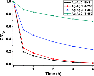 | ||
| Fig. 9 Adsorption and visible light degradation performance of different thermally annealed Ag-AgCl-T-Z photocatalysts for MB removal. | ||
4 Conclusion
In this work, a synergistic strategy comprising adsorption and degradation to efficiently remove high concentrations of methylene blue dye has been demonstrated using novel nano-hybrid plasmonic photocatalysts. The titanate nanotube template was proved to be indispensable for high adsorption ability in this work, and the anchored Ag-AgX NPs are used as plasmonic photocatalysts to achieve visible light activity. The ratio of monomer peak intensity (Im) to dimer peak intensity (Id) of MB reflects the dominance by adsorption or degradation: the process is dominated by adsorption when the Id/Im ratio decreases, and by photocatalytic degradation when the ratio increases. Among the silver halides, the Ag-AgCl-TNT hybrid exhibits the highest photocatalytic activity due to the greater amount of Ag NPs and enhanced visible light absorption induced by the surface plasmonic effect. The synthetic approach is generic and can be extended to the preparation of other dual-phase photocatalysts for high concentration organic dye removal.Acknowledgements
The authors thank the Environment and Water Industry Programme Office (EWI) under the National Research Foundation of Singapore (grant MEWR651/06/160) for the financial support of the work. Z. Jiang wishes to thank the support from the C. N. Yang Scholars Programme at Nanyang Technological University.References
- X. B. Chen, S. H. Shen, L. J. Guo and S. S. Mao, Chem. Rev., 2010, 110, 6503–6570 CrossRef CAS.
- X. Q. Chen, J. H. Ye, S. X. Ouyang, T. Kako, Z. S. Li and Z. G. Zou, ACS Nano, 2011, 5, 4310–4318 CrossRef CAS.
- A. Fujishima, X. T. Zhang and D. A. Tryk, Surf. Sci. Rep., 2008, 63, 515–582 CrossRef CAS.
- X. L. Hu, G. S. Li and J. C. Yu, Langmuir, 2010, 26, 3031–3039 CrossRef CAS.
- D. Zhao, C. C. Chen, Y. F. Wang, H. W. Ji, W. H. Ma, L. Zang and J. C. Zhao, J. Phys. Chem. C, 2008, 112, 5993–6001 CAS.
- D. J. Yang, H. W. Liu, Z. F. Zheng, Y. Yuan, J. C. Zhao, E. R. Waclawik, X. B. Ke and H. Y. Zhu, J. Am. Chem. Soc., 2009, 131, 17885–17893 CrossRef CAS.
- Y. Liao, W. Que, Q. Jia, Y. He, J. Zhang and P. Zhong, J. Mater. Chem., 2012, 22, 7937–7944 RSC.
- P. Chen, L. Gu, X. Xue, M. Li and X. Cao, Chem. Commun., 2010, 46, 5906–5908 RSC.
- J. G. Yu, Y. R. Su and B. Cheng, Adv. Funct. Mater., 2007, 17, 1984–1990 CrossRef CAS.
- C. Zhu, S. Guo, P. Wang, L. Xing, Y. Fang, Y. Zhai and S. Dong, Chem. Commun., 2010, 46, 7148–7150 RSC.
- D. Gong, V. P. Subramaniam, J. G. Highfield, Y. Tang, Y. Lai and Z. Chen, ACS Catal., 2011, 1, 864–871 CrossRef CAS.
- Y. H. Cheng, Y. Huang, P. D. Kanhere, V. P. Subramaniam, D. Gong, S. Zhang, J. Highfield, M. K. Schreyer and Z. Chen, Chem.–Eur. J., 2011, 17, 2575–2578 CrossRef CAS.
- T. Kasuga, M. Hiramatsu, A. Hoson, T. Sekino and K. Niihara, Langmuir, 1998, 14, 3160–3163 CrossRef CAS.
- L. Zhu, L. Gu, Y. Zhou, S. Cao and X. Cao, J. Mater. Chem., 2011, 21, 12503–12510 RSC.
- Y. X. Tang, Y. K. Lai, D. G. Gong, K. H. Goh, T. T. Lim, Z. L. Dong and Z. Chen, Chem.–Eur. J., 2010, 16, 7704–7708 CrossRef CAS.
- D. J. Yang, Z. F. Zheng, H. Y. Zhu, H. W. Liu and X. P. Gao, Adv. Mater., 2008, 20, 2777–2781 CrossRef CAS.
- Y. X. Tang, D. G. Gong, Y. K. Lai, Y. Q. Shen, Y. Y. Zhang, Y. Z. Huang, J. Tao, C. J. Lin, Z. L. Dong and Z. Chen, J. Mater. Chem., 2010, 20, 10169–10178 RSC.
- S. Linic, P. Christopher and D. B. Ingram, Nat. Mater., 2011, 10, 911–921 CrossRef CAS.
- Z. G. Yi, J. H. Ye, N. Kikugawa, T. Kako, S. X. Ouyang, H. Stuart-Williams, H. Yang, J. Y. Cao, W. J. Luo, Z. S. Li, Y. Liu and R. L. Withers, Nat. Mater., 2010, 9, 559–564 CrossRef CAS.
- P. Wang, B. B. Huang, X. Y. Qin, X. Y. Zhang, Y. Dai, J. Y. Wei and M. H. Whangbo, Angew. Chem., Int. Ed., 2008, 47, 7931–7933 CrossRef CAS.
- C. Hu, Y. Q. Lan, J. H. Qu, X. X. Hu and A. M. Wang, J. Phys. Chem. B, 2006, 110, 4066–4072 CrossRef CAS.
- Y. P. Bi and J. H. Ye, Chem. Commun., 2009, 6551–6553 Search PubMed.
- J. G. Yu, G. P. Dai and B. B. Huang, J. Phys. Chem. C, 2009, 113, 16394–16401 CAS.
- Y. G. Sun, J. Phys. Chem. C, 2010, 114, 2127–2133 CAS.
- M. S. Zhu, P. L. Chen and M. H. Liu, ACS Nano, 2011, 5, 4529–4536 CrossRef CAS.
- Y. X. Tang, V. P. Subramaniam, T. H. Lau, Y. K. Lai, D. G. Gong, P. D. Kanhere, Y. H. Cheng, Z. Chen and Z. L. Dong, Appl. Catal., B, 2011, 106, 577–585 CrossRef CAS.
- C. Hu, T. W. Peng, X. X. Hu, Y. L. Nie, X. F. Zhou, J. H. Qu and H. He, J. Am. Chem. Soc., 2010, 132, 857–862 CrossRef CAS.
- Y. Bi, H. Hu, S. Ouyang, G. Lu, J. Cao and J. Ye, Chem. Commun., 2012, 48, 3748–3750 RSC.
- H. Wang, Y. S. Bai, J. T. Yang, X. F. Lang, J. H. Li and L. Guo, Chem.–Eur. J., 2012, 18, 5524–5529 CrossRef CAS.
- P. Wang, B. B. Huang, Q. Q. Zhang, X. Y. Zhang, X. Y. Qin, Y. Dai, J. Zhan, J. X. Yu, H. X. Liu and Z. Z. Lou, Chem.–Eur. J., 2010, 16, 10042–10047 CrossRef CAS.
- M. Zhu, P. Chen and M. Liu, J. Mater. Chem., 2011, 21, 16413–16419 RSC.
- L. Han, P. Wang, C. Zhu, Y. Zhai and S. Dong, Nanoscale, 2011, 3, 2931–2935 RSC.
- Y. Hou, X. Li, Q. Zhao, X. Quan and G. Chen, J. Mater. Chem., 2011, 21, 18067–18076 RSC.
- C. An, X. Ming, J. Wang and S. Wang, J. Mater. Chem., 2012, 22, 5171–5176 RSC.
- G. Tian, Y. Chen, H.-L. Bao, X. Meng, K. Pan, W. Zhou, C. Tian, J.-Q. Wang and H. Fu, J. Mater. Chem., 2012, 22, 2081–2088 RSC.
- D. Wang, Y. Duan, Q. Luo, X. Li, J. An, L. Bao and L. Shi, J. Mater. Chem., 2012, 22, 4847–4854 RSC.
- T. S. Wu, S. Liu, Y. L. Luo, W. B. Lu, L. Wang and X. P. Sun, Nanoscale, 2011, 3, 2142–2144 RSC.
- Y. Bi, S. Ouyang, N. Umezawa, J. Cao and J. Ye, J. Am. Chem. Soc., 2011, 133, 6490–6492 CrossRef CAS.
- Z. Z. Lou, B. B. Huang, X. Y. Qin, X. Y. Zhang, H. F. Cheng, Y. Y. Liu, S. Y. Wang, J. P. Wang and Y. Dai, Chem. Commun., 2012, 48, 3488–3490 RSC.
- H. Wang, J. Gao, T. Guo, R. Wang, L. Guo, Y. Liu and J. Li, Chem. Commun., 2012, 48, 275–277 RSC.
- H. Wang, X. F. Lang, J. Gao, W. Liu, D. Wu, Y. M. Wu, L. Guo and J. H. Li, Chem.–Eur. J., 2012, 18, 4620–4626 CrossRef CAS.
- M. Zhu, P. Chen and M. Liu, Langmuir, 2012, 28, 3385–3390 CrossRef CAS.
- Y. Tang, Z. Jiang, J. Deng, D. Gong, Y. Lai, H. T. Tay, I. T. K. Joo, T. H. Lau, Z. Dong and Z. Chen, ACS Appl. Mater. Interfaces, 2012, 4, 438–446 CAS.
- Y. Zhang, Y. Tang, S. Yin, Z. Zeng, H. Zhang, C. M. Li, Z. Dong, Z. Chen and X. Chen, Nanoscale, 2011, 3, 4074–4077 RSC.
- R. Z. Ma, Y. Bando and T. Sasaki, Chem. Phys. Lett., 2003, 380, 577–582 CrossRef CAS.
- P. Wang, B. B. Huang, X. Y. Zhang, X. Y. Qin, H. Jin, Y. Dai, Z. Y. Wang, J. Y. Wei, J. Zhan, S. Y. Wang, J. P. Wang and M. H. Whangbo, Chem.–Eur. J., 2009, 15, 1821–1824 CrossRef CAS.
- J. Zhao, C. Chen and W. Ma, Top. Catal., 2005, 35, 269–278 CrossRef CAS.
- T. Zhang, T. k. Oyama, S. Horikoshi, H. Hidaka, J. Zhao and N. Serpone, Sol. Energy Mater. Sol. Cells, 2002, 73, 287–303 CrossRef CAS.
- K. Bergmann and C. T. O'Konski, J. Phys. Chem., 1963, 67, 2169–2177 CrossRef CAS.
- C. An, S. Peng and Y. Sun, Adv. Mater., 2010, 22, 2570–2574 CrossRef CAS.
Footnote |
| † These authors contributed equally to this work. |
| This journal is © The Royal Society of Chemistry 2012 |
