Biosilica structures with controllable morphology produced by an electrochemical process on indium tin oxide surfaces†
Ruixiang
Wu
,
Yong
Li
,
Qinrong
Wang
,
Jun
Yu
,
Feng
Jiang
,
Fangfang
Wang
and
Xin
Zhang
*
Department of Chemistry, Science Faculty, Shantou University, Shantou, 515063, China. E-mail: xzhang@stu.edu.cn; Fax: 86 754 82903639
First published on 6th August 2012
Abstract
In this paper, the formation of stable and continuous inorganic coating on indium tin oxide (ITO) via biosilica polymerization in the presence and absence of externally imposed electrostatic fields is described. The electrostatic fields exert a stronger influence on poly-L-lysines (PLLs) with a lower molecular weight than on larger ones. The larger peptides only enhance the density and uniformity of the biosilica deposition, whereas the overall biosilica morphology is observed to shift from sphere- to club-like structures when smaller PLLs are used. To explore the biosilica formation mechanism under precisely controlled electrostatic fields, scanning electron microscopy, circular dichroism, and atomic force microscopy were used to investigate the process of polypeptide tailored silica precipitation. Our results indicated that electric fields result in a high concentration of polypeptide near the ITO surfaces, which can be used as organic templates and basic building blocks to provide opportunities for tailoring material morphologies.
1. Introduction
Silica materials are gaining fundamental and technological interest as one of the most technologically important inorganic compounds. The applications of these materials are diverse, from catalysis and separation media, to enzyme immobilization and drug release.1–8 The chemical synthesis of silica-based materials often requires extreme pH, high temperature, or toxic organic reagents. Thus, compatibility with biomolecules such as proteins and peptides is hindered. By contrast, the formation of biosilica with precisely controlled morphologies in nature is controlled by proteins and polysaccharides under mild conditions.6,9Learning from nature, researchers investigated how proteins and polysaccharides guide and control the biosilicification process in the synthesis of complex structures, in order to understand the possible mechanisms involved. Biomimetic syntheses have been conducted using macromolecules (such as proteins, polypeptides, and diblock polymers) as templates to direct the silica biomineralization process in an in vitro environment.10–16 Chemical and physical conditions, including external force fields, were used to facilitate the morphological control of the resulting silica. However, the fabrication of stable silica structures remains a challenge, because conventional organic aggregates have difficulty growing a stable one-dimensional template on a substrate surface for silica deposition.17–20 To overcome these limitations, silica morphologies have been manipulated using external physical fields resulting from the participation of various polypeptides in the biomimetic process. For example, Rodriguez et al.21 studied the influence of various chemical and physical parameters on the peptide-mediated silica morphology. They observed that overall silica morphologies transform from sphere to fiber and dendrite-like structures when externally applied force fields were introduced. Stone et al.22 synthesized arched and elongated biosilica structures using a synthetic peptide by manipulating the physical reaction environment. They provided evidence that in vitro biocatalysis can be controlled to form the desired silica structures. Glawe et al.23 employed electric fields to control the deposition of poly-L-lysine (PLL) to indium tin oxide (ITO) surfaces, and demonstrated the ability to spatially control the formation of silica on the surface. Their results suggest that electrostatic interactions between bioinspired molecules and silica species are an important factor in facilitating the synthesis of silica under ambient conditions. Similarly, Pogula et al.24 examined polypeptide-based macromolecules that can mediate the formation of inorganic material coatings on glass fibers. They observed that some macromolecules can heal composite fibers, in addition to the matrix. Compared with the extensive investigation of chemical factors (e.g. pH, template, concentration, and additives), the effects of physical stimulation (such as electric field) on peptides are studied less. Consequently, a detailed understanding of molecular mechanisms underlying the biosilication and biomimetic synthesis of patterned silica, as affected by external fields, remains elusive.
In our previous biomineralization studies using polypeptides, chemical/physical influences such as molecular weights, pH, concentration, and flow dynamic field on biosilica structures have been extensively investigated, and multiple morphologies have been successfully obtained.25,26 To determine the specific and quantitative roles of electrostatic fields, and to understand the possible underlying mechanisms, the current paper explored a controlled physical influence on the silica biomineralization process using a simple cationic peptide, PLL, as an organic template. The morphologies and conformation of the products were examined by scanning electron microscopy (SEM) and circular dichroism (CD), respectively. Liquid atomic force microscopy (AFM) was also performed to investigate the in situ observation of the nucleation and growth mechanism, and a possible formation mechanism was suggested.
2. Materials and methods
2.1. Materials
All reagents and PLL·HBr (PLL1, molecular weight (Mw) = 5 kDa; PLL2, Mw = 70 kDa; and PLL3, Mw = 150 kDa) were purchased from Sigma-Aldrich Chemical Co. and used without further purification unless otherwise noted. Deionized ultrafiltered water was used for washing the centrifuged samples. ITO-covered glass slides purchased from Shenzhen CSG Electronics Co. (China) were sequentially cleaned with Alconox solution, acetone and deionized water, respectively.2.2. Preparation of biosilica
Details of the experimental procedure have previously been reported.27,28 In a typical experiment, silicic acid was freshly prepared by ultrasonicating 200 μL of tetraethoxysilane (TEOS) in 1.5 mL HCl (1 mM) for 30 min. Then, 10 μL PLL solution (6 mg mL−1) was premixed with 30 μL phosphate-buffered saline (PBS, 0.1 M, pH 7.2) before the addition of silicic acid precursor solution. For the electric field peptide deposition tests, a 4 V electric potential was applied (Fig. 1a). As soon as the externally applied electrostatic field was deactivated, the cathode surface was washed with PBS solution to remove free polypeptides that did not attach to the electrode surface. Silicic acid was then placed on the flat cathode surface and allowed to react with the polypeptide-patterned surface for 1–2 min (Fig. 1b). The surface was then washed with double-distilled deionized water prior to imaging. After the desired reaction time, i.e. 5, 10, 20 and 30 min, the samples were centrifuged at 14![[thin space (1/6-em)]](https://www.rsc.org/images/entities/char_2009.gif) 000 r min−1 for 10 min. After removing the supernatant, the white precipitate was rinsed three times with distilled water and ethanol to remove the unreacted TEOS and the residual polymer. This dispersion was further diluted and a few drops of the solution were placed on SEM sample holders and left to dry under ambient conditions.
000 r min−1 for 10 min. After removing the supernatant, the white precipitate was rinsed three times with distilled water and ethanol to remove the unreacted TEOS and the residual polymer. This dispersion was further diluted and a few drops of the solution were placed on SEM sample holders and left to dry under ambient conditions.
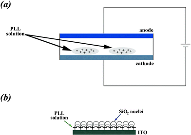 | ||
| Fig. 1 (a) Schematic diagram of the experimental setup. PLL is attached to the ITO surface under an applied electrostatic field. An ITO-covered glass slide is used as a variable work electrode, and Cu wires act as reference and counter electrodes, respectively. (b) Silicic acid reacts with PLL at the surface of the cathode electrode. | ||
2.3. Sample characterization
000 cm−1 to 400 cm−1.
3. Results and discussion
3.1. Influence of PLL
Peptide-tailored biosilica structures can be chemically and physically influenced. SEM was used to investigate the biosilica morphology in the presence and absence of electric fields using PLLs with different molecular weights (Fig. 2). The biosilica morphologies can transform from sphere-like particles (Fig. 2a), obtained using the short-chain PLL1, into hexagonal particles (Fig. 2b and 2c), obtained using longer-chain PLLs (PLL2 and PLL3), under static conditions because of its conformation and self-assembly ability. This observed characteristic proves that the polymer chain length strongly affects the morphology of the silica precipitate in the absence of an electric field, which is consistent with previous studies on the formation of silica structures regulated by PLL.31,32 The electrostatic influence was then explored by applying an electrostatic field to the peptide solution on the ITO surface. Interestingly, the overall biosilica morphologies obtained are found to shift from spherical to club-like particles under identical solution conditions, depending on the PLL1 used for biomineralization and the profound effect of the electrostatic field (Fig. 2d). The results of the electrostatic field experiments suggested that the externally applied electrostatic field results in a high concentration of PLLs near the surface of the ITO cathode, thereby controlling the deposition and orientation of silicic on the electrode surface. The PLL orientation was restricted when attached to the ITO surface, and the peptide-mediated reaction produces various silica structures that depend on the molecular weight of the polypeptide and the strength of the electric field. However, under similar conditions, only sphere-like biosilica has been obtained in the presence of applied force fields.21 A possible reason for this discrepancy may be related to the 4 V electrical potential used, which is higher than that used in previous research (1 V). This finding supports the idea that the strength of the electric field is also an important factor in controlling the biosilica structure. By contrast, when larger PLLs (PLL2 and PLL3) were used, plate-like silica structures with a denser silica distribution are obtained compared with the morphologies formed in the absence of an electrical field (Fig. 2e and 2f), consistent with previous research results.21,23 Therefore, compared with PLLs with larger molecular weights, electrostatic fields more strongly influence smaller PLLs.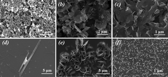 | ||
| Fig. 2 Scanning electron micrographs (SEM) of silica structures. The silica structures are obtained under static conditions using (a) PLL1, (b) PLL2 and (c) PLL3. (d) Clubbed silica structures are obtained after electrostatic field-assisted deposition of PLL1 at the ITO surface. (e) Biosilica platelets with a denser distribution, obtained after electrostatic field assisted deposition of PLL2 at the ITO surface. (f) Loosely organized silica platelets obtained after electrostatic field assisted deposition of PLL3 at the ITO surface. | ||
3.2. Influence of external field
To gain a better insight into the role of environmental influences during the process of biomineralization, we have investigated the different concentrations of PLL1 peptide and strengths of electrostatic fields that affect the silicification conditions (Fig. S1 and S2, ESI†). The results revealed that a lower concentration of peptide or potential of the electrostatic fields produced sphere-like biosilica, and a high concentration of peptide (6 mg mL−1) and potential of the electrostatic fields (4 V) generally favor the formation of biosilica with a clubbed shape. Thus, regular morphologies of biosilica could be controlled through careful adjustment of chemical/physical factors.21,23Subsequently, SEM was employed as a function of time to explore the intermediate stages of coating formation during the different biomineralization stages. Fig. 3 shows the progressive increase of biosilica induced by PLL1 (6 mg mL−1), with reaction times from 5 min to 30 min in the presence of controlled electrostatic fields (4 V). Fig. 3a shows that single particles are formed during the initial stages of mineralization, and the particle nuclei depend on both the nucleating site number of PLL and silicic acid concentration. The interactions between the positively charged PLL and the negatively charged silica result in the close proximity of the neighboring reactive silicate precursors present in the peptide backbone or in neighboring PLL chains. Thus, induced by the polypeptide molecules, the microspheres are transformed into club-like spheres and further assemble at the surface in the next 10 to 20 min (Fig. 3b and 3c). When the reaction time is further extended to 30 min, the particle structures change noticeably, i.e. complete and smooth club-like biosilica are found (Fig. 3d). The nucleation and growth of silicic acid to form nanoparticles and small particles are directed by the polypeptides. This finding indicates that they can be used as basic building blocks to obtain new materials by self-assembly. The subsequent growth of silica is due to particle aggregation or “necking” among the coalesced particles. The unique morphology is then solidified by the continuous growth of silica, which can be described as “assembly-aggregation-silicification”. However, as the reaction progresses further, these larger aggregates do not undergo significant changes in size, most likely because the surface PLL residues provide most of the catalytic sites for the nucleation reaction. Once these charges on the template surface are completely neutralized or embedded by the adsorbed silica anions over increasing silicification times, further increases in reaction time only lead to the formation of random silica precipitates. These results agree well with previous reports regarding time-dependent particle growth and coalescence in the presence of additives for biomineralization.33
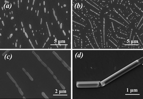 | ||
| Fig. 3 SEM images of biosilica produced by PLL under an applied electrostatic field with reaction times of (a) 5 min, (b) 10 min, (c) 20 min and (d) 30 min, respectively. | ||
To obtain more information about the formation mechanism of PLL-induced biomimetic synthesis of silica, tapping mode AFM was used to track the reaction process of PLL-directed silica biomineralization with or without externally applied electrostatic fields. Fig. 4 shows a series of AFM micrographs taken from the PLL-mediated silica biomineralization in phosphate buffer at the ITO surface in the absence or presence of electric fields. Fig. 4a presents the AFM spectrum of PLL1 in PBS solution before the addition of silicic acid, in which a number of extremely small nanoparticles are found under static conditions. After the injection of freshly prepared silicic acid into the chamber, PLL exhibits an immediate response to silicic acid when they are mixed together; larger nanoparticles are uniformly distributed on the surface of the assembled PLL within a short period of time (Fig. 4b). However, in the presence of electrostatic fields, the PLL/phosphate anion complex is, surprisingly, observed to self-assemble into clubbed nanoparticles on the ITO surface (Fig. 4c). The addition of silicic acid to the PLL/phosphate mixture does not induce a significant change, but smooth/clubbed silica aggregates are observed when the reaction time is further extended (Fig. 4d). Consistent with the SEM results, the PLL/phosphate anion mixture possibly functions as a basic scaffold to tailor silica deposition with the continuous growth of small particles. Therefore, after injecting TEOS, silicic acid ions with negatively charged groups react with the positively charged groups of PLL to form stable nuclei via static electric absorption. The externally applied electric field causes a local area of high polypeptide concentration around the ITO cathode surface. The PLL residues on the ITO surface, as organic template, provide catalytic sites for nucleation reaction with TEOS. The nucleation and growth of silica acid to form nanoparticles is directed by PLL. Thus, they can be considered as basic building blocks in obtaining new materials through self-assembly. This direct visual process is similar to previous reports on nanoparticle assembly and biomimetic mineralization.14,34–36
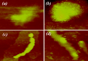 | ||
| Fig. 4 The 1 μm × 1 μm atomic force microscopy (AFM) images under static conditions in the presence of (a) PLL/phosphate and (b) PLL/phosphate/silicic acid. AFM images under electrostatic fields in the presence of (c) PLL/phosphate and (d) PLL/phosphate/silicic acid. The Z-scale for all images is 20 nm. | ||
The formation of PLL1 on the ITO surface was verified by CD measurements to demonstrate the variation in the secondary structures of PLL1 in the absence or presence of an electric field. The CD spectrum of PLL1 in the phosphate buffer solution exhibits a minimum at approximately 198 nm, indicating that the short-chain peptide predominantly adopts a random coil conformation under neutral pH conditions (Fig. 5a). Short-chain PLLs are known to be unstable and fail to adopt a helical structure, which is due to the insufficient number of intramolecular hydrogen bonds to stabilize the structure. This finding agrees with previous reports on the formation of silica particles with PLLs having chain lengths of fewer than 100 amino acid residues.29,30 Interestingly, when PLL1 was attached to the ITO surface, the peptide spectra displayed two main features: a negative band at 200 nm and a positive band at 218 nm (Fig. 5b). The former is attributed to a random coil conformation, whereas the latter may be due to a β-turn structure,37–39 indicating that the externally applied force fields are sufficient to induce a secondary structural transition. Subsequently, the addition of silicic acid causes negligible changes in the shape of the CD spectra, compared with that of the peptide solution in pure water, suggesting that the primary conformation remains a β-turn structure. The results suggest that the deposited PLL1 retained its ability to condense silica and that the externally applied electric field can influence the conformation of polypeptide, which, in turn, influences the silica structure. Such a transition from a β-turn structure to a random coil in the secondary structure of PLL1 is required to form regular clubbed silica particles, confirming the idea that the conformation of polypeptide is a key factor in controlling overall silica morphology. These observations agree with the SEM and AFM results, which show that regular club-like silica structures are formed via self-assembly where PLLs act as basic building blocks.
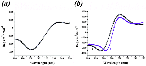 | ||
| Fig. 5 (a) Circular dichroism (CD) spectra in the presence of PLL/phosphate under static conditions. (b) CD spectra in the absence (curve 1) or presence (curve 2) of silicic acid under an electrostatic field. | ||
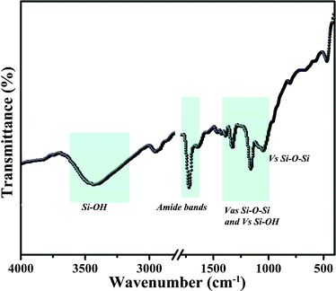
FT-IR, EDS, and TGA were performed on the peptide and the aforementioned silica materials to further investigate the entrapment of PLL molecules within the silica. The FT-IR confirmed the biosilica formation (Fig. 6). The predominant peak regions arising from PLL and silica are highlighted on the plot and characterized as follows: 3700–2800 cm−1 OH stretching modes from adsorbed water and silanol groups. Two other characteristic bands at 1715 and 1652 cm−1 are also observed and attributed to amide I (vC![[double bond, length as m-dash]](https://www.rsc.org/images/entities/char_e001.gif) O) and amide II (δN–H) bands from the polypeptide, respectively.31,40 The hybrid silica (i.e. polypeptide silica composite) displays three characteristic silica peaks: 1200–900 cm−1 Si–O–Si asymmetric stretching and Si–OH symmetric stretching modes.41 In general, the FT-IR spectra provide evidence of the conformation of PLL in the silica samples. The EDS analysis also verifies the coexistence of polymer and silica within individual hybrid particles (Fig. S3, ESI†). TGA was used to determine the number of soft templates contained in the as-synthesized particles (Fig. S4, ESI†). There was about 9% weight loss before 200 °C in the TGA curve, which could be attributed to the loss of water present in the biosilica sample. The major weight loss occurs at approximately 220–450 °C, in which more than 16% of the mass loss is due to peptide combustion. These characterization results indicate the successful silicification of the peptide.
O) and amide II (δN–H) bands from the polypeptide, respectively.31,40 The hybrid silica (i.e. polypeptide silica composite) displays three characteristic silica peaks: 1200–900 cm−1 Si–O–Si asymmetric stretching and Si–OH symmetric stretching modes.41 In general, the FT-IR spectra provide evidence of the conformation of PLL in the silica samples. The EDS analysis also verifies the coexistence of polymer and silica within individual hybrid particles (Fig. S3, ESI†). TGA was used to determine the number of soft templates contained in the as-synthesized particles (Fig. S4, ESI†). There was about 9% weight loss before 200 °C in the TGA curve, which could be attributed to the loss of water present in the biosilica sample. The major weight loss occurs at approximately 220–450 °C, in which more than 16% of the mass loss is due to peptide combustion. These characterization results indicate the successful silicification of the peptide.
A mechanism that defines the effects of electric fields on the self-assembly of polypeptide aggregates can be proposed, based on the above analysis (Fig. 7). In the absence of an electric field, individual silica spheres and/or platelets can be obtained under static conditions. When larger PLLs are used, plate-like silica structures with a denser silica distribution can be obtained under an applied electric field. However, clubbed silica structures can be obtained when PLL1 is absorbed on the ITO surface under identical conditions. The specific shape and orientation of the silica attached onto the surface are possibly due to the polypeptide orientation on the cathode, which indicates that the externally applied electric field causes polypeptide aggregation around the ITO cathode surface. The surface hydroxyl groups on ITO can be regarded as an effective platform in facilitating protein immobilization.20,42 The electrostatic fields more strongly influence PLLs with smaller molecular weights. For PLL1, the clubbed morphology of the distinctly shaped particles resulting from exposure of the polypeptide-coated surface to electric fields was different from the morphology that results from static reaction in solution. For PLL2 and PLL3, the silica platelet is perpendicular to the electrode surface, which suggests that the growth continues beyond the peptide-coated surface. Thus, only plate-like silica morphologies with a dense distribution can be found after introducing external electric fields in larger PLL systems. The hydrogen-bonded network of the self-assembled template is responsible for interfacial molecular recognition at the organic/inorganic interface during crystallization.43,44 The aforementioned CD and AFM analyses, together with the SEM results that mediate the formation of silica, also verified our model. From the above analysis, the silica structures obtained on the ITO surfaces with PLL suggest that the conformation of the polypeptide, as well as the influence of externally applied force fields, plays a key role in controlling the overall morphology. Still, a more detailed analysis on the role of the electrostatic field and biomineralization is still currently being conducted.
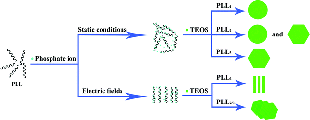 | ||
| Fig. 7 Schematic presentation of the formation of silica mediated by PLL with different molecular weights in the absence or presence of an electric field. | ||
4. Conclusions
The present study shows that PLL can easily be coated on ITO surfaces as templates in biosilica synthesis with or without the assistance of an externally applied electrostatic field. In the absence of an electrostatic field, biosilica morphologies transformed from sphere-like to hexagonal particles. However, under the influence of an externally applied electrostatic field, larger peptides only enhanced the density and uniformity of the biosilica deposition, whereas the overall biosilica morphologies were observed to shift from sphere-like to clubbed structures with smaller PLLs. Thus, the electrostatic fields exert a stronger influence on PLLs with smaller molecular weights. This finding demonstrates the possibility of controlling the local deposition of polypeptide and subsequent silica formation on the surface, using externally well-defined electrostatic fields. A wide variety of shapes can be used as templates for the synthesis of biosilica particles or for the construction of three-dimensional structures. An easy and feasible bioinspired synthetic method of controlling the resulting biosilica morphologies after exposure to a pulsed electric field was proposed. The relationship between the externally applied stimulation and bioinspired molecules was also elucidated.Acknowledgements
The authors are grateful to the Natural Science Foundation of China (20871080) and Innovation Team Construction Project of Shantou University (ITC11002) for financial support.References
- Y. F. Zhu, J. L. Shi, W. H. Shen, X. P. Dong, J. W. Feng, M. L. Ruan and Y. S. Li, Angew. Chem., Int. Ed., 2005, 44, 5083–5087 CrossRef CAS.
- I. I. Slowing, B. G. Trewyn, S. Giri and V. S. Lin, Adv. Funct. Mater., 2007, 17, 1225–1236 CrossRef CAS.
- R. K. Pai and S. Pillai, Cryst. Growth Des., 2007, 7, 215–217 CAS.
- X. Li, T. Yang, Q. Gao, J. Yuan and S. Cheng, J. Colloid Interface Sci., 2009, 338, 99–104 CrossRef CAS.
- H. Ehrlich, R. Deutzmann, E. Brunner, E. Cappellini, H. Koon, C. Solazzo, Y. Yang, D. Ashford, J. Thomas-Oates, M. Lubeck, C. Baessmann, T. Langrock, R. Hoffmann, G. Wörheide, J. Reitner, P. Simon, M. Tsurkan, A. V. Ereskovsky, D. Kurek, V. V. Bazhenov, S. Hunoldt, M. Mertig, D. V. Vyalikh, S. L. Molodtsov, K. Kummer, H. Worch, V. Smetacek and M. J. Collins, Nat. Chem., 2010, 2, 1084–1088 CrossRef CAS.
- S. V. Patwardhan, Chem. Commun., 2011, 47, 7567–7582 RSC.
- H. Q. Wu, B. B. Tang and P. Y. Wu, J. Phys. Chem. C, 2012, 116, 2246–2252 CAS.
- L. M. Pan, Q. J. He, J. N. Liu, Y. Chen, M. Ma, L. L. Zhang and J. L. Shi, J. Am. Chem. Soc., 2012, 134, 5722–5725 CrossRef CAS.
- A. W. Xu, Y. R. Ma and H. Cölfen, J. Mater. Chem., 2007, 17, 415–449 RSC.
- J. N. Cha, G. D. Stucky, D. E. Morse and T. J. Deming, Nature, 2000, 403, 289–292 CrossRef CAS.
- R. H. Jin and J. J. Yuan, Adv. Mater., 2009, 21, 3750–3753 CrossRef CAS.
- L. Xia, Y. Liu and Z. B. Li, Macromol. Biosci., 2010, 10, 1566–1575 CrossRef CAS.
- H. Xu, Y. Wang, X. Ge, S. Han, S. Wang, P. Zhou, H. Shan, X. Zhao and J. R. Lu, Chem. Mater., 2010, 22, 5165–5173 CrossRef CAS.
- L. Xia and Z. B. Li, Langmuir, 2011, 27, 1116–1122 CrossRef CAS.
- S. J. Wang, X. Ge, J. Y. Xue, H. M. Fan, L. J. Mu, Y. P. Li, H. Xu and J. R. Lu, Chem. Mater., 2011, 23, 2466–2474 CrossRef CAS.
- J. J. Yuan and R. H. Jin, J. Mater. Chem., 2012, 22, 5080–5088 RSC.
- K. J. C. van Bommel, A. Friggeri and S. Shinkai, Angew. Chem., Int. Ed., 2003, 42, 980–999 CrossRef CAS.
- J. Jiang, T. Wang and M. Liu, Chem. Commun., 2010, 46, 7178–7180 RSC.
- X. B. Zhao, F. Pan, H. Xu, M. Yaseen, H. H. Shan, C. A. E. Hauser, S. G. Zhang and J. R. Lu, Chem. Soc. Rev., 2010, 39, 3480–3498 RSC.
- Y. Qiao, H. Chen, Y. Lin, Z. Yang, X. Cheng and J. Huang, J. Phys. Chem. C, 2011, 115, 7323–7330 CAS.
- F. Rodriguez, D. D. Glawe, R. R. Naik, K. P. Hallinan and M. O. Stone, Biomacromolecules, 2004, 5, 261–265 CrossRef CAS.
- R. R. Naik, P. K. Whitlock, F. Rodríguez, L. L. Brott, D. D. Glawe, S. J. Clarson and M. O. Stone, Chem. Commun., 2003, 238–239 RSC.
- D. D. Glawe, F. Rodriguez, M. O. Stone and R. R. Naik, Langmuir, 2005, 21, 717–720 CrossRef CAS.
- S. D. Pogula, S. V. Patwardhan, C. C. Perry, J. W. Gillespie, S. Yarlagadda and K. L. Kick, Langmuir, 2007, 23, 6677–6683 CrossRef CAS.
- N. Li, X. Zhang, Q. R. Wang, F. F. Wang and P. K. Shen, RSC Adv., 2012, 2, 3288–3297 RSC.
- F. F. Wang, F. Jiang, Y. Li, Q. R. Wang and X. Zhang, RSC Adv., 2012, 2, 5738–5747 RSC.
- S. V. Patwardhan, N. Mukherjee and S. J. Clarson, J. Inorg. Organomet. Polym., 2001, 11, 193–198 CrossRef CAS.
- W. D. Marner, A. S. Shaikh and S. J. Muller, Biomacromolecules, 2008, 9, 1–5 CrossRef CAS.
- L. Yang, H. M. Li, K. M. Wang, W. H. Tan, W. J. Yang and J. Zheng, Anal. Chem., 2008, 80, 6222–6227 CrossRef CAS.
- S. Y. Han, W. W. Xu, M. W. Cao, J. Q. Wang, D. H. Xia, H. Xu, X. B. Zhao and J. R. Lu, Soft Matter, 2012, 8, 645–652 RSC.
- M. M. Tomczak, D. D. Glawe, L. F. Drummy, C. G. Lawrence, M. O. Stone, C. C. Perry, D. J. Pochan, T. J. Deming and R. R. Naik, J. Am. Chem. Soc., 2005, 127, 12577–12582 CrossRef CAS.
- S. V. Patwardhan, R. Maheshwari, N. Mukherjee, K. L. Kiick and S. J. Clarson, Biomacromolecules, 2006, 7, 491–497 CrossRef CAS.
- Z. P. Zhang, D. M. Gao, H. Zhao, C. G. Xie, G. J. Guan, D. P. Wang and S. H. Yu, J. Phys. Chem. B, 2006, 110, 8613–8618 CrossRef CAS.
- R. K. Pai and S. Pillai, J. Am. Chem. Soc., 2008, 130, 13074–13078 CrossRef CAS.
- R. K. Pai, S. Hild, A. Ziegler and O. Marti, Langmuir, 2004, 20, 3123–3128 CrossRef CAS.
- H. Ehrlich, T. Hanke, C. Fischer, A. Frolov, T. Langrock, R. Hoffmann, U. Schwarzenbolz, T. Henle, R. Born and H. Worch, J. Biomed. Mater. Res. B. Appl. Mater., 2010, 92, 542–551 Search PubMed.
- B. A. Clack and D. M. Gray, Biopolymers, 1989, 28, 1861–1873 CrossRef CAS.
- T. Yamaoka, T. Tamura, Y. Seto, T. Tada, S. Kunugi and D. A. Tirrell, Biomacromolecules, 2003, 4, 1680–1685 CrossRef CAS.
- Y. Cho, L. B. Sagle, S. Iimura, Y. J. Zhang, J. Kherb, A. Chilkoti, J. M. Scholtz and P. S. Cremer, J. Am. Chem. Soc., 2009, 131, 15188–15193 CrossRef CAS.
- K. M. Hawkins, S. S. S. Wang, D. M. Ford and D. F. Shantz, J. Am. Chem. Soc., 2004, 126, 9112–9119 CrossRef CAS.
- A. Fidalgo and L. M. Ilharco, J. Non-Cryst. Solids, 2001, 283, 144–154 CrossRef CAS.
- H. T. Ng, A. P. Fang, L. Q. Huang and S. F. Y. Li, Langmuir, 2002, 18, 6324–6329 CrossRef CAS.
- M. Sarikaya, C. Tamerler, A. K. Y. Jen, K. Schulten and F. Baneyx, Nat. Mater., 2003, 2, 577–585 CrossRef CAS.
- A. F. Wallace, J. J. DeYoreo and P. M. Dove, J. Am. Chem. Soc., 2009, 131, 5244–5250 CrossRef CAS.
Footnote |
| † Electronic supplementary information (ESI) available. See DOI: 10.1039/c2ra21326e |
| This journal is © The Royal Society of Chemistry 2012 |