Close-packed mesoporous carbon polyhedrons derived from colloidal carbon microspheres for electrochemical energy storage applications
Siyuan
Yang
a,
Baohua
Zhang
ab,
Chunyu
Ge
a,
Xianming
Dong
a,
Xiaotang
Liu
a,
Yueping
Fang
*a,
Hongqiang
Wang
b and
Zesheng
Li
*b
aInstitute of Biomaterials, College of Science, South China Agricultural University, Guangzhou, 510642, China. E-mail: ypfang@scau.edu.cn
bKey Laboratory for the Chemistry and Molecular Engineering of Medicinal Resources (Ministry of Education of China), School of Chemistry & Chemical Engineering of Guangxi Normal University, Guilin, 541004, P. R. China. E-mail: lzs212@163.com; Tel: 86-20-85285565; Fax: 86-20-85285565
First published on 3rd September 2012
Abstract
A new class of mesoporous carbon polyhedrons (MCPs) with a facet-to-facet close-packed model are presented for the first time as electrode materials for electrochemical capacitors (ECs). These MCPs are evolved directly from the colloidal carbon microspheres (CCMs) by a new silica-free approach, the top-down carbonate (Li2CO3) site-occupying strategy. The obtained polyhedral materials consist of a desirable mesoporous structure with mesopores with a mean size of about 30 nm. The unique structures of the large-size mesopores in a close-packed combination are considered to provide a more favourable pathway for electrolyte penetration and transportation, as well as good electronic conductivity for electrochemical energy storage applications. Accordingly, the resultant mesoporous materials show great promise for high performance EC applications, of which high energy and high power properties are desirable.
Introduction
Mesoporous carbon materials (2 nm < pore size <50 nm)—a class of functional carbon materials—have demonstrated great potential applications in many fields, such as separation, adsorption, catalysis, gas storage, energy storage, controlled drug delivery and so on, owing to their large pore volume, highly accessible surface area as well as their excellent thermal and chemical stability.1 It was demonstrated early on that mesoporous carbons with uniform and interconnected pores can be synthesized by using mesoporous silicas as hard templates followed by rigorous silica removal.2 Nowadays, a variety of convenient silica-free approaches for fabricating highly mesoporous carbons have been developed, which are of particular interest for their large-scale production and application.3Recently, great research emphasis has been placed on the synthesis of micro- and nanosized materials with polyhedral morphology, including metal polyhedrons, metal oxide polyhedrons, organic metal polyhedrons, etc.4 Such polyhedral architectures usually exhibit very high thermodynamical stability and superior chemical-reaction activities. More recently, several important studies on graphite polyhedrons have initiated the development of carbonaceous polyhedral materials.5 However, to the best of our knowledge, polyhedral carbons with highly mesoporous structures have not been reported yet although such materials seem very attractive in various applications.
Colloidal Carbon Microspheres (CCMs), also called carbonaceous polysaccharide microspheres, form a class of interesting functional carbon materials with a carbon-rich core and a polysaccharide outer layer, which are usually prepared from glucose under moderate hydrothermal conditions.6 Currently, CCMs are widely used as sacrificial templates for the synthesis of various metal oxide hollow spheres,7 or as precursors for the preparation of solid carbon spheres,8 but are rarely used in syntheses for porous carbon materials,9 especially in direct approaches to mesoporous carbon.
In the present investigation, we report the syntheses of unique mesoporous carbon polyhedrons (MCPs) directly evolved from CCMs via a newly silica-free approach, the “top-down” carbonate (Li2CO3) “site-occupying” strategy, which is characterized by a consecutive DMF-swelling, Li-embedding and Li-dislodging procedure. For this synthetic strategy, three features become apparent over previous reports:1–3 (i) the top-down approach allows easy fabrication of mesoporous carbon with good-shaped morphology from the starting material; (ii) the developed procedure favors the polyhedral carbon with a facet-to-facet close-packed model; and (iii) the potential molten salt route provides a possible synthesis of mesoporous carbon without additional template removal. Furthermore, by integrating the advantages of close-packed architectures and mesoporous nanostructures, the obtained MCPs become promising electrode materials for high performance electrochemical capacitor (EC) applications with high energy and high power properties.
Experimental
Materials synthesis
CCMs were first achieved in high yield by an easy hydrothermal strategy reported previously6. Afterwards, a consecutive DMF-swelling, Li-embedding and Li-dislodging procedure is applied to prepare MCPs from CCMs. (i) DMF-swelling: 0.50 g of as-synthesized CCMs was dispersed in 50 ml DMF under ultrasonic treatment for 30 min. During the ultrasonic irradiation, the temperature of the reaction solution rose to around 60 °C. (ii) Li-embedding: 0.50 g of CH3COOLi was added into the above mixture, ultrasonically treated sequentially for 30 min, and then 2 ml of deionized water was added and sonicated for another 30 min. The black monolithic products (MCP precursor) were isolated by filtration in 220 nm organic membranes. (iii) Li-dislodging: the as-prepared MCP precursor was than sintered under Ar atmosphere in a two-step sintering procedure. Firstly, the temperature of the system was raised from room temperature to 550 °C at a rate of 2 °C min−1 for 1 h. Secondly, the temperature was raised from 550 °C to 850 °C at a rate of 2 °C min−1 for 2 h. Finally, the temperature was allowed to cool to room temperature at a rate of 5 °C min−1. For the sake of comparison, microporous carbons were prepared by routine alkaline chemical activation with CCMs as carbon sources and LiOH or KOH as activating agents. Typically, the CCMs was mixed with LiOH or KOH (1![[thin space (1/6-em)]](https://www.rsc.org/images/entities/char_2009.gif) :
:![[thin space (1/6-em)]](https://www.rsc.org/images/entities/char_2009.gif) 4, wt./wt.) in deionized water, and then the mixture was heated at 2 °C min−1 up to 850 °C and was held for 2 h under Ar flow.
4, wt./wt.) in deionized water, and then the mixture was heated at 2 °C min−1 up to 850 °C and was held for 2 h under Ar flow.
Material characterization
The structure and morphology of the as-prepared samples were analyzed by field-emission scanning electron microscopy (FE-SEM) (Philips, FEI Quanta 200 FEG), and transmission electron microscopy (TEM) (JEOL-2010 microscope operated at 200 kV). In order to study the electrochemical performance, the MCPs were designed as part of monolithic electrodes for electrochemical capacitors. Cyclic voltammetry (CV) curves and electrochemical impedance spectroscopy (EIS) were recorded using an electrochemical workstation (ZAHNER IM6, Germany).Results and discussion
Fig. 1 (a) and (c) show the typical large-area SEM images of the CCMs powder and MCPs, respectively. Fig. 1 (b) and (d) show the partially enlarged SEM images from Fig. 1 (a) and (c), respectively. These images indicate the presence of two kinds of good-shaped, relatively homogeneous microspheres with sizes of 450 ± 50 nm. However, a lot of distinct facets are presented on the surface of the MCPs, which is quite different from the absolute sphericity of the CCMs. The SEM observation demonstrated the successful synthesis of polyhedral carbon spheres directly from colloidal carbon spheres. Interestingly, the majority of these polyhedral carbon spheres (see Fig. 1 (d)) are joined together at one of their facets (labelled with arrows) hinting at the original sites where their growth began and interacted with polyhedrons. This type of formation is quite similar to the recently proposed dumbbell-like construction for nanoparticles. The interfacial interactions originating from the nanometer contact between two nanoparticles can induce new collective properties, such as higher electrical and thermal conductivity relative to the individual counterparts.10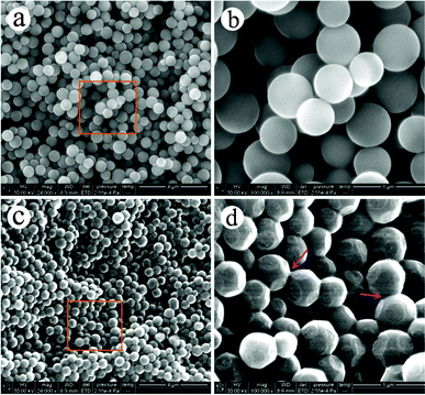 | ||
| Fig. 1 SEM images of CCMs (a, b) and MCPs (c, d) at different magnification. | ||
The typical TEM images of CCMs and MCPs are presented in Fig. 2, which reveal the detailed structural evolution from CCMs to MCPs. On one hand, TEM observation shows that the CCMs have full solid sphere structures with diameters of 400–500 nm (Fig. 2 (a)), and a typical hexagonal-close-packed (HCP) assembly11 (see images (1) and (2) in Fig. 2 (a)). On the other hand, the TEM observation reveals the nice mesoporous and polyhedral structures of the MCPs (see Fig. 2(b)). Firstly, the lower magnification image shows the characteristics of 3-D self-assembly and highly close-packed structures for the MCPs. Secondly, two magnified images of single MCPs (images (1) and (2) in Fig. 2 (b)) show clearly the polyhedral morphologies (surface angles of 120–130°) and good mesoporous structures (about 30 nm in pore size). Furthermore, a schematic model for these close-packed MCPs (left) and the pore size distribution (right) from nitrogen adsorption/desorption is portrayed in Fig. 2 (c). These mesopores of MCPs might be perforated by the facet-to-facet connections of polyhedrons in the close-packed model. Nitrogen adsorption/desorption shows that these MCP mesopores have a larger-size distribution with more than 85% pores in the range 20–40 nm (SBET = 512.8 m2 g−1). All these results demonstrate that we have synthesized mesopore-functional carbon polyhedrons directly from colloidal carbon spheres.
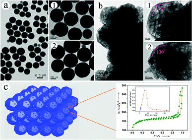 | ||
| Fig. 2 Typical TEM images of (a) CCM and (b) MCP samples, and (c) schematic model of close-packed MCPs (left) and pore size distribution (right) from nitrogen adsorption/desorption. Images of (b) and (d) are taken from the squares in (a) and (c), respectively. | ||
To show further insight into the detailed nanostructure and growth process of the MCPs, high-resolution SEM images of the MCP precursor and MCP hemisphere are presented in Fig. 3. Fig. 3 (a) presents a typical SEM image of the MCP precursor, also showing a clear polyhedral morphology and good facet-to-facet construction. The corresponding TEM image (insert of Fig. 3 (a)) reveals a very close 120° surface angle in the interface between the three polyhedrons, indicating a growth trend in the HCP structure cell of MCPs. In addition, the higher magnification SEM images (images (1) and (2) in Fig. 3 (a)) of the MCP precursor demonstrate that they are composed of extremely small granular components of about 10 nm in their both external and internal dimensions. Fig. 3 (b) presents a typical SEM image of the MCP hemisphere obtained by an ultrathin section technique. The insert is the corresponding TEM image of the MCP hemisphere. It is apparent that these MCP hemispheres have a highly mesoporous structure with loopholes of 50–150 nm in the close-packed model. The diameter of the pores ranges from 25 nm to 35 nm (see SEM images (1) and (2) in Fig. 3 (b)). All these results are in good agreement with the findings of the TEM observations mentioned above.
 | ||
| Fig. 3 High-resolution SEM images of (a) MCP precursors and (b) MCP hemispheres (the inserts are the corresponding TEM images). | ||
The proposed mechanism for MCPs involving polyhedron and mesopore growth processes is schematically shown in Fig. 4. On the one hand, the formation of polyhedral structures of MCPs could be attributed to three main factors in the precursor stage: (i) the HCP-type self-assembly of CCMs; (ii) DMF swelling of the assembled CCMs; and (iii) surface modification of swelled CCMs by lithium acetate. The third factor seems to be a decisive cause that the hydrophilic property of the CCM surface declined greatly due to depression of surface hydroxyl group (–OH). Hence, on the basis of least-energy principles (minimum surface energy), the swelled CCMs can lead to a maximum compression with lots of contacting interfaces in the precursor stage, and thus contribute ultimately to the generation of polyhedral constructs in MCPs.
 | ||
| Fig. 4 Schematic illustration of the synthetic procedure of the MCPs. | ||
On the other hand, the growth of the mesoporous structures of MCPs depends on the “top-down” Li2CO3 “site-occupying” strategy in the consecutive DMF-swelling, Li-embedding and Li-dislodging procedure. In this process, the DMF-swelling step may play a role in recovering the carbon-rich core of CCMs to the polysaccharide with abundant –OH groups.6,7 Promoted by ultrasonic effects, lithium acetate (Li source) could easily be embedded into the matrix of the swelled CCMs and a possible acetic ester and lithium hydroxide were generated, by the esterification between CH3COO– and –OH groups [see eqn (1)].
| (R-OH)n + n CH3COOLi ⇒ nCH3COOR + nLiOH | (1) |
Subsequently, the LiOH enclosed in the swelled CCMs (bottom of Fig. 4) were first converted in situ into nanoscale Li2CO3 at the first temperature platform (550 °C for 1 h) [see eqn (2)].
| LiOH + CH3COOR ⇒ Li2CO3 + H2O | (2) |
As the temperature increased (550–850 °C), the Li2CO3 content decreased, and disappeared at 850 °C (see Fig. 5). It is proposed that these Li2CO3 (618 °C in melting point) were mostly melt, and dislodged out from the carbonized framework of CCMs under the second temperature platform (850 °C for 2 h), thus resulting in the mesoporous structures of the MCPs (see Fig. 6).
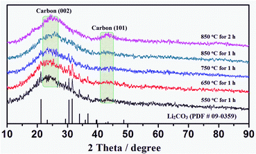 | ||
| Fig. 5 XRD patterns of MCPs at a continuously varying temperature platform. | ||
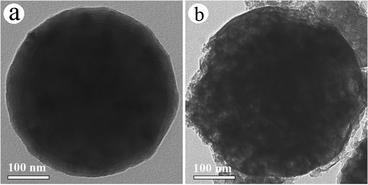 | ||
| Fig. 6 Typical TEM images of MCPs after sintering: (a) 550 °C for 1 h and (b) 850 °C for 2 h. | ||
Recently, a family of “bottom-up” methods using nanoscale metallic compounds (e.g. MgO, TiO2 and CaCO3) as the hard template and saccharides as the starting material was reported to construct mesoporous carbon materials.12 These strategies belong to the advisable silica-free synthesis routes, though they are still require strong acid or alkali dissolution for the step of template removal. However, due to the unformed shape of the precursor materials, the configurations of the resultant mesoporous carbons achieved by these methods are difficult to control for given shapes. Fortunately, the present “top-down” strategy suggests its superiority, as it allows a shape-controllable synthesis of mesoporous carbon derived from the good-shaped and homogeneous colloidal carbon spheres. At the same time, the potential molten salt route also provides a possible preparation of mesoporous carbon without additional template removal. On the other hand, differently from the routine alkaline chemical activation (KOH or LiOH) towards micropore carbon,13 the porous structure of carbon material (MCPs) in this case was dominant in abundant mesopores and the prototype of the precursor could be well preserved (see Fig. 7 for details). These results are basically attributed to the “site-occupying” function of nano-Li2CO3 as well as the mild Li-embedding process under relatively low temperature (around 60 °C). In particular, this could provide the possibility to tailor the porous structure of such mesoporous carbons from large-sized mesopores to smaller mesopores, by controlling the size of Li2CO3 at an appropriate temperature platform and heating rate in a sintering step. In addition, it is worthwhile to note that our strategy would become a general approach for the preparation mesoporous carbon materials by using a wide range of biomass-derived carbonaceous precursor materials from hydrothermal routes.14
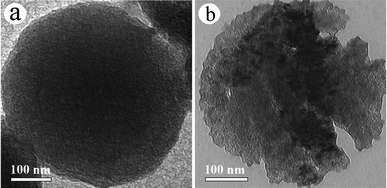 | ||
| Fig. 7 Typical TEM images of the microporous carbon prepared by routine alkaline chemical activation: (a) LiOH activation; and (b) KOH activation. | ||
Over the years, significant attention has been directed towards the design and fabrication of monolithic carbon materials.15 Owing to their structural stability and collective properties, such engineerable carbon monoliths have been demonstrated enormous potential for many up-to-date technology applications, including energy storage materials, catalyst supports and biomedical materials.15 Intriguingly, it is found that a highly close-packed MCP precursor monolith could be readily accomplished with the present synthetic protocol, by using the monodispersed CCMs as raw material without any binder medium (see Fig. 8 for details). In addition, the shapes of the carbon monoliths can be designed into desirable structure models, such as a disk-like shape with a predetermined size and thickness, via a facile injection molding technique in the filtration step (see Fig. 9 (a)). Subsequently, the disk-like MCP monolith can be fabricated by a careful high-temperature sintering process. In particular, we found that visible Li2CO3 (white powder) remains on the bottom of the porcelain combustion boat after high temperature sintering (see Fig. 9 (b)). In addition, the ICP-AES analysis confirms that less than 0.25 w.% Li element remained in the MCP product. Consequently, it is reasonable to conclude that Li2CO3 should be the final phase state of the Li-source, which was mostly melt, and dislodged out from the framework of MCP monoliths.
 | ||
| Fig. 8 Pictures of (a) CCMs, (b) filtrated CCMs and (c) MCP precursor. | ||
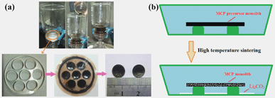 | ||
| Fig. 9 Illustrations for the (a) tailoring of MCP precursor monolith and (b) fabrication of MCP monolith. | ||
Electrochemical capacitors (ECs), or so-called supercapacitors (SCs), are electrochemical energy storage systems which store energy by forming a double-layer capacitance or pseudo-capacitance between electrolyte ions and the surface of the active electrodes.16 Mesoporous carbon materials with a large-size distribution have been proposed as promising electrode materials for double-layer ECs, because of their favourable pathway for electrolyte penetration and transportation.17 In addition, the monolithic mesoporous carbons are of particular interest in technical applications due to their advantages of high packing density and their binder-free nature.3a,18 Based on the analysis of the aforementioned results, we hereby investigated the potential performance of the resultant MCP monolith as electrode materials for supercapacitors in a 6.0 mol L−1 KOH aqueous solution.19 The electrochemical properties of the MCP electrode are simply evaluated by a cyclic voltammetry testing technique, with the results shown in Fig. 10.
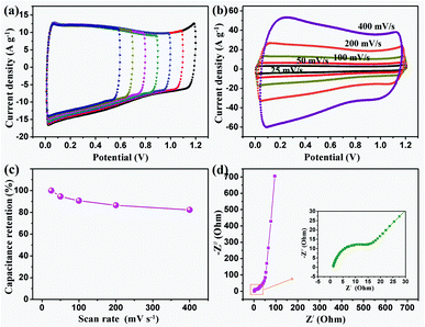 | ||
| Fig. 10 Electrochemical properties of the MCP electrode: (a) CV curves recorded at a scan rate of 100 mV s−1 over various voltage windows; (b) CV curves recorded at different scan rates; (c) capacitance retention to scan rates and (d) Nyquist plots from EIS. | ||
In the first place, at a scan rate of 100 mV s−1, normally rectangular curves were achieved over a wide range of voltage windows from 0.0 V to 0.6–1.2 V (see Fig. 10 (a)). The ideal capacitance characteristics indicate that the MCP electrode has a highly accessible surface area resulting from the rational mesoporous texture. In the second place, the shapes of the rectangular curves keep nearly the same with the increase of the scan rate from 25 to 400 mV s−1 (see Fig. 10 (b)), suggesting that the electrode has a high conductivity and good power capability. Thus, excellent results demonstrated for the MCP electrode might be caused by the unique close-packed structures arising from nanometer contact with the polyhedrons. Likewise, such close-packed architectures of the MCPs would lead to a desirable energy performance for electrochemical energy storage. The specific capacitance were attained from the CV curves with values of 123.2, 116.6, 111.7, 106.5 and 101.4 F g−1, obtained at scan rates of 25, 50, 100, 200 and 400 mV s−1, respectively. In particular, a superior capacity retention of 84.3% can be achieved at a relatively high scan rate of 400 mV s−1 (see Fig. 10 (c)). It is noteworthy that the Nyquist plots from EIS analysis (see Fig. 10 (d)) also confirms the desirable capacitance performance with low initial interfacial resistance (the diameter of the semi-circle) and a high mass transfer rate (the slope of the inclined line).20 As a whole, all these results persuade us to propose the novel mesoporous carbon materials as promising candidates for energy storage applications with high energy and high power properties.
Conclusions
In summary, a novel polyhedral carbon material with a good mesoporous structure is presented for the first time, via a new silica template-free route directly from glucose-derived colloidal carbon spheres. Our work suggests a new, general working mechanism, namely the “top-down” Li2CO3 “site-occupying” strategy, for the growth of good-shaped mesoporous carbon from the established carbonaceous precursors. Moreover, the close-packed carbon polyhedrons could be assembled spontaneously into a monolith in the absence of any binder medium in the precursor stage. This unique property could be applied to develop shape-engineerable high-packing-density porous carbon materials of macroscopic dimensions. These carbon materials should be capable of diverse applications as varied as gas separation, water purification, chromatography, catalysis, hydrogen storage and electrodes for electrochemical devices.Acknowledgements
This research was supported by the NSF of China (20963002, 21173088 and 21105030), the key Academic Program of the 3rd phase “211 Project” of South China Agricultural University.References
- (a) C. Liang, Z. Li and S. Dai, Angew. Chem., Int. Ed., 2008, 47, 3696 CrossRef CAS; (b) E. Ramasamy and J. Lee, Chem. Commun., 2010, 46, 2136 RSC; (c) Z. Li, Q. Li, Y. Fang, H. Wang, Y. Li and X. Wang, J. Mater. Chem., 2011, 21, 17185 RSC; (d) H. Jiang, T. Sun, C. Li and J. Ma, RSC Adv., 2011, 1, 954 RSC.
- (a) J. Lee, S. Han and T. Hyeon, J. Mater. Chem., 2004, 14, 478 RSC; (b) Y. Zhang, A. Wang and T. Zhang, Chem. Commun., 2010, 46, 862 RSC.
- (a) H. Liu, X. Wang, W. Cui, Y. Dou, D. Zhao and Y. Xia, J. Mater. Chem., 2010, 20, 4223 RSC; (b) L. Guo, J. Zhang, Q. He, L. Zhang, J. Zhao, Z. Zhu, W. Wu, J. Zhang and J. Shi, Chem. Commun., 2010, 46, 7127 RSC; (c) M. Inagaki, H. Orikasa and T. Morishita, RSC Adv., 2011, 1, 1620 RSC.
- (a) N. Tian, Z. Zhou, S. Sun, Y. Ding and Z. Wang, Science, 2007, 316, 732 CrossRef CAS; (b) S. E. Habas, H. Lee, V. Radmilovic, G. A. Somorjai and P. Yang, Nat. Mater., 2007, 6, 692 CrossRef CAS; (c) Y. Ma, Q. Kuang, Z. Jiang, Z. Xie, R. Huang and L. Zheng, Angew. Chem., Int. Ed., 2008, 47, 8901 CrossRef CAS; (d) K. Nanda, A. Maisels and F. R. Kruis, RSC Adv., 2011, 1, 568 RSC.
- (a) Y. Gogotsi, J. Libera, N. Kalashnikov and M. Yoshimura, Science, 2000, 290, 317 CrossRef CAS; (b) H. Okuno, A. Palnichenko, J. Despres, J. Issi and J. Charlier, Carbon, 2005, 43, 692 CrossRef CAS; (c) M. Ishihara, A. Koshio, A. Nakayama, Y. Koga and F. Kokai, Mater. Lett., 2007, 61, 1068 CrossRef CAS.
- X. Sun and Y. Li, Angew. Chem., Int. Ed., 2004, 43, 597 CrossRef.
- (a) X. Sun and Y. Li, Angew. Chem., Int. Ed., 2004, 43, 3827 CrossRef CAS; (b) X. Sun, J. Liu and Y. Li, Chem.–Eur. J., 2006, 12, 2039 CrossRef CAS.
- R. Yang, H. Li, X. Qiu and L. Chen, Chem.–Eur. J., 2006, 12, 4083 CrossRef CAS.
- Q. Wang, H. Li, L. Chen and X. Huang, Carbon, 2001, 39, 2211 CrossRef CAS.
- (a) J. Zhang, H.G. Liu, Z. Wang and N. Ming, Adv. Funct. Mater., 2007, 17, 3295 CrossRef CAS; (b) C. Wang, C. Xu, H. Zeng and S. Sun, Adv. Mater., 2009, 21, 3045 CrossRef CAS.
- (a) P. Ni, P. Dong, B. Cheng, X. Li and D. Zhang, Adv. Mater., 2001, 13, 437 CrossRef CAS; (b) Y. Li, T. Sasaki, Y. Shimizu and N. Koshizaki, J. Am. Chem. Soc., 2008, 130, 14755 CrossRef CAS.
- (a) T. Morishita, Y. Soneda, T. Tsumura and M. Inagaki, Carbon, 2006, 44, 2360 CrossRef CAS; (b) C. A. Filho and A. J. Zarbin, Carbon, 2006, 44, 2869 CrossRef; (c) B. Xu, L. Peng, G. Wang, G. Cao and F. Wu, Carbon, 2010, 48, 2377 CrossRef CAS.
- E. Vilaplana-Ortego, M. A. Lillo-Ródenas, J. Alcañiz-Monge, D. Cazorla-Amorós and A. Linares-Solano, Carbon, 2009, 47, 2141 CrossRef CAS.
- (a) X. Cui, M. Antonietti and S. Yu, Small, 2006, 2, 756 CrossRef CAS; (b) B. Hu, K. Wang, L. Wu, S. Yu, M. Antonietti and M. Titirici, Adv. Mater., 2010, 22, 813 CrossRef CAS.
- (a) D. Carriazo, F. Picó, M. C. Gutiérrez, F. Rubio, J. M. Rojo and F. D. Monte, J. Mater. Chem., 2010, 20, 773 RSC; (b) G. Hao, W. Li, D. Qian and A. Lu, Adv. Mater., 2010, 22, 853 CrossRef CAS; (c) K. Okada, M. Nandi, J. Maruyama, T. Oka, T. Tsujimoto, K. Kondoh and H. Uyama, Chem. Commun., 2011, 47, 7422 RSC.
- (a) P. Simon and Y. Gogotsi, Nat. Mater., 2008, 7, 845 CrossRef CAS; (b) H. Q. Wang, Z. S. Li, Y. G. Huang, Q. Y. Li and X. Y. Wang, J. Mater. Chem., 2010, 20, 3883 RSC; (c) P. Si, S. Ding, X. Lou and D. Kim, RSC Adv., 2011, 1, 1271 RSC.
- (a) S. R. S. Prabaharan, R. Vimala and Z. Zainal, J. Power Sources, 2006, 161, 730 CrossRef CAS; (b) H. Wang, Z. Li, J. Yang, Q. Y. Li and X. Zhong, J. Power Sources, 2009, 194, 1218 CrossRef CAS.
- (a) H. Yang and D. Zhao, J. Mater. Chem., 2005, 15, 1217 CAS; (b) M. Gutierrez, F. Pico, F. Rubio, J. Amarilla, F. Palomares, M. Ferrer, F. Monte and J. Rojo, J. Mater. Chem., 2009, 19, 1236 RSC.
- (a) Q. Li, Z. Li, L. Lin, X. Wang, Y. Wang, C. Zhang and H. Wang, Chem. Eng. J., 2010, 156, 500 CrossRef CAS; (b) C. Yuan, X. Zhang, L. Su, B. Gao and L. Shen, J. Mater. Chem., 2009, 19, 5772 RSC.
- (a) H. Li, X. J. Huang and L. Q. Chen, J. Power Sources, 1999, 81–82, 340 CrossRef CAS; (b) D. Liu, Q. Wang, L. Qiao, F. Li, D. Wang, Z. Yang and D. He, J. Mater. Chem., 2012, 22, 483 RSC; (c) M. Liu, L. Kong, C. Lu, X. Li, Y. Luo and L. Kang, RSC Adv., 2012, 2, 1890 RSC.
| This journal is © The Royal Society of Chemistry 2012 |
