Preparation of poly(vinyl alcohol) nanocomposites with molybdenum disulfide (MoS2): structural characteristics and markedly enhanced properties
Keqing
Zhou
,
Saihua
Jiang
,
Chenlu
Bao
,
Lei
Song
,
Bibo
Wang
,
Gang
Tang
,
Yuan
Hu
* and
Zhou
Gui
*
State Key Laboratory of Fire Science, University of Science and Technology of China, Jinzhai Road 96, Hefei, Anhui, 230027, P. R. China. E-mail: yuanhu@ustc.edu.cn (Y. Hu); zgui@ustc.edu.cn (Z. Gui); Fax: +86-551-3601664; +86-551-3601669; Tel: +86-551-3601664; +86-551-3601288
First published on 2nd October 2012
Abstract
As a graphene-like layered nano-material, molybdenum disulfide (MoS2) has gained much attention from the materials fields. In our research, MoS2/poly(vinyl alcohol) (PVA) nanocomposites are prepared by solvent blending method. The morphology, thermal properties, fire resistance properties and mechanical properties of the PVA/MoS2 nanocomposites are studied. MoS2 is homogeneously dispersed and partially exfoliated in the PVA matrix as indicated by X-ray diffraction (XRD) pattern, Fourier transform infrared spectroscopy (FTIR) and transmission electron microscopy (TEM) characterization. The thermogravimetric analysis (TGA) and differential scanning calorimetry (DSC) results indicate improved the thermal decomposition temperature and the glass transition temperature (Tg). The thermal degradation temperature is increased by 20–40 °C. Meanwhile, the peak of heat release rate (pHRR) and total heat release (THR) are decreased by 33% and 20%, respectively. Storage modulus at 40 °C is increased by 28%, and the tensile strength is increased by 24% upon addition of 1 wt% and 5 wt% MoS2. The improvements in the thermal properties, fire resistance properties and mechanical properties of PVA nanocomposites are attributed to the good dispersion of MoS2, physical barrier effects of MoS2 and strong interactions between PVA and MoS2.
1. Introduction
Over the past eight years, graphene, a monolayer form of carbon with a two-dimensional (2D) honeycomb lattice, has attracted a great deal of attention due to its fascinating electronic, mechanical, optical, flexible and thermal properties. Graphene has sparked enormous interest from various fields such as electronic and energy devices,1–3 catalysts,4,5 sensors,6,7 high-performance fibers8 and composites.9,10 Owing to the high specific area and dramatic properties, 2D materials are promising for many applications. Besides graphene, a wide range of inorganic layered materials such as transition metal dichalcogenides (TMDs)11 have been successfully synthesized.Among these 2D layered materials, molybdenum disulfide (MoS2) is one of the most attractive. MoS2 has a similar structure with graphite. The basic unit of MoS2 is composed of a molybdenum atom coordinated with six sulfur atoms. It is organized in two layers of sulfur atoms forming a sandwich structure, with a layer of molybdenum atoms in the middle. Each sulfur atom is coordinated with three molybdenum atoms within a single 2D layer of MoS2. The bulk material is formed of these 2D layers held together by van der Waals forces. Due to the weak van der Waals interactions between the sheets, MoS2 has a low friction coefficient and thus gives rise to its superior lubricating properties.12 The applications of MoS2 include catalysts, transistors and polymer nanocomposites.13–18 In addition, the layered structure of MoS2 enables easy intercalation of metal ions, such as Li+ and Mg2+.19–21 It is convenient to prepare the polymer nanocomposites by the intercalation of metal ions (Li+) and then exfoliation to a single or few layers through the hydrolysis of the Li+.
Organic/inorganic hybrid materials, based on interactions between organic and inorganic components, have been greatly developed in the past decades. Among them, polymer nanocomposites consist of a polymer matrix and layered nano-fillers have gained a lot of interest in the past two decades due to their markedly enhanced properties. In the early ages of the polymer nanocomposites research, layered silicates and layered double hydroxides (LDHs) are the most widely investigated.22–27 However, in the present, graphene-based nano-materials have dominated in this field.28-30 When polymer and layered inorganic components are blended at the molecular level, many properties can be obviously improved, including mechanical properties, thermal stability, fire resistance, and gas permeability, etc.31,32,38,39,42
Poly(vinyl alcohol) (PVA) is a water soluble polymer with many desirable characteristics, such as biocompatibility, biodegradability, and water-solubility. It is obtaining increasing attention in various applications such as proton-exchange membranes and polymer electrolyte fuel cells,33 separation applications,34 permeability membranes,35 drug delivery,36 and packaging materials.37 These applications have stimulated interest in improving the properties of PVA. According to the reported literature, many efforts have been made to prepare high-performance PVA nanocomposites. For example, Kawakage reported an increased storage modulus in PVA/clay blends.40 Huang et al. reported the preparation of PVA-based nanocomposites with pristine layered double hydroxides and apparently improved its mechanical properties.41 Bao et al. studied the structure and properties of graphene/PVA nanocomposites and graphite oxide/PVA nanocomposites contrastively and discussed the mechanism for the property enhancements.42 As is well-known, the dispersion and interface interactions of nanofillers in a polymer matrix are two key factors for property enhancements.42 For the PVA matrix, dispersion and interface interactions are mainly related to the hydroxyl groups in the PVA and the nano-fillers.43,44 If there are abundant hydroxide groups in the nano-fillers, good dispersion and strong interactions of the nano-fillers in the PVA matrix and significant property improvements are available.
MoS2 has been incorporated into many polymer matrices such as polyanilines, polythiophene, polypyrrol and poly[oxymethylene-(oxyethylene)] to prepare polymer nanocomposites.16–18,45 As far as we know, these researches are mainly concentrated on their conductive performance in these literatures. Few of them have dealt with the thermal, mechanical and fire safety properties of the composites.46 Molybdenum, as a transition metal element, can catalyze the char formation of polymers and sulfur can improve the flame retardancy of polymers.47,48 Moreover, as a typical layered inorganic material, MoS2 is expected to disperse and exfoliate in polymers and results in the physical barrier effects which inhibit the diffusion of heat and the decomposition products of the polymer. Due to the combination of the above factors, it is reasonable that MoS2 may improve the thermal stability, mechanical properties and fire resistance of polymer-based composites just like montmorillonite (MMT) and LDHs.
In this paper, PVA/MoS2 nanocomposites were prepared by the solvent blending and casting method. The synthetic route of the PVA/MoS2 nanocomposites was shown in Scheme 1. The thermal stability, fire resistance and mechanical properties of the resulting materials were investigated. Mechanisms of the improved properties are discussed. Moreover, the water solution blending method opens a new avenue to fabricate MoS2-based nanocomposites of water-soluble polymers on a large scale and effectively for more extensive applications.
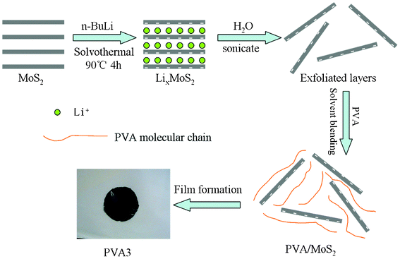 | ||
| Scheme 1 Illustration of the preparation process of the PVA nanocomposites. | ||
2. Materials and experimental method
2.1 Materials
PVA (polymerization degree 1750 ± 50, CP), molybdenum disulfide (MoS2, AP) and n-hexane (AP), had the moisture removed with the coronizing molecular sieve after being purchased from Sinopharm Chemical Reagent Co., Ltd. (China). The n-butyl lithium (2.2 M in hexane) was purchased from Alfa Aesar without further purification. The distilled water was produced in our laboratory.2.2 Preparation of LixMoS2
LixMoS2 was prepared by the solvothermal methodology, similar to the preparation procedure of LixWS2.49 In a typical experiment, 1.0 g MoS2 was put into the autoclave and 36 mL 0.5 M solution of n-butyl lithium in hexane was then added. The autoclave was tightly sealed and heated at 90 °C for 4 h. The product was filtered, washed with anhydrous hexane, and then dried at 60 °C in vacuum oven.2.3 Exfoliation of MoS2
Exfoliation of MoS2 into single-molecule layers was achieved via the rapid hydrolysis and ultrasonication of LixMoS2. In a typical reaction, 0.5 g LixMoS2 was hydrolysed in 1 L water, and ultrasonicated at ambient temperature for 4 h to produce a colloidal suspension of single-molecule MoS2 layers. The suspension was neutralized with dilute acid (1 M nitric acid).182.4 Preparation of PVA/MoS2 nanocomposite
PVA/MoS2 nanocomposites were prepared by the ultrasonic solvent-casting technique. Scheme 1 shows the synthesis strategy. The formulations of the PVA/MoS2 nanocomposites is listed in Table 1.| Sample | Component |
|---|---|
| PVA0 | PVA |
| PVA1 | PVA/MoS2 (1%) |
| PVA2 | PVA/MoS2 (3%) |
| PVA3 | PVA/MoS2 (5%) |
| PVA4 | PVA/MoS2 (10%) |
To prepare PVA/MoS2 nanocomposites, PVA was dissolved in deionized water at 90 °C in a three-neck flask with mechanical stirring to prepare PVA aqueous solution. Then, the required MoS2 aqueous suspension was dripped into the PVA solution which was then stirred at 90 °C for 48 h. At last, the blending was cast onto glass plates and dried at 40 °C in an oven for 24 h to form flat membranes which were peeled off and further heated at 80 °C for 48 h to remove residual water. The obtained membranes were cut into pieces for tests.
2.5 Characterization techniques
X-ray diffraction (XRD) was performed using a Japan Rigaku D/Max-Ra rotating-anode X-ray diffractometer equipped with a Cu-Kα tube and a Ni filter (λ = 0.1542 nm). The scanning rate was 4° min−1. MoS2 was measured as powders, whereas PVA nanocomposites were measured as membranes. The scanning range was 5–65°.Transmission electron microscopy (TEM, JEM-2100F, Japan Electron Optics Laboratory Co., Ltd.) was employed to investigate the micro-morphology of the PVA nanocomposites. The accelerating voltage was 200 kV. Before observation, PVA nanocomposites were cut into ultrathin sections using a CM1900 microtome (Leica, Wetzlar, Germany). The ultrathin sections were transferred from liquid nitrogen to carbon-coated copper grids and then observed by TEM.
Scanning electron microscopy (SEM) image of the residue after calcination at 600 °C for 20 min in air was taken using a DXS-10 scanning electron microscope produced by Shanghai Electron Optical Technology Institute. The char was adhibited onto the copper plate, and then coated with gold/palladium alloy ready for imaging.
Fourier transform infrared (FTIR) spectra were obtained with a Nicolet 6700 spectrometer (Nicolet Instrument Corporation, Madison, WI). MoS2 powders, pure PVA and the PVA/MoS2 nanocomposites were mixed with KBr powders and pressed into tablets for characterization. All the samples were analyzed with the transmission mode and the wavenumber range was set from 4000 to 500 cm−1.
Thermogravimetric analysis (TGA) was carried out using a Q5000 thermoanalyzer instrument (TA Instruments Inc., New Castle, DE) under air flow of 25 mL min−1. In each case, the samples (5–10 mg) were heated from room temperature (30 °C) to 700 °C at a linear heating rate of 20 °C min−1. Two parallel runs were performed with each sample. TGA and differential thermogravimetric (DTG) curves were plotted.
Differential scanning calorimetry (DSC) was performed using a Perkin-Elmer Pyris Diamond DSC-7. Samples (2–4 mg) were heated from 0 to 120 °C at a linear heating rate of 10 °C min−1; the temperature was kept at 120 °C for 10 min and then decreased from 120 to 0 °C at a linear rate of 10 °C min−1. This heating-cooling cycle was repeated, and the data obtained from the second heating section were plotted.
Microscale combustion colorimeter (MCC-2) was used to investigate the flammability characteristics of PVA nanocomposites according to ASTM D7309-07. Samples of about 5 mg were heated in nitrogen atmosphere at a constant heating rate of 1 °C s−1 from room temperature to 650 °C. The decomposition products were mixed with oxygen (20 mL min−1) and then combusted in the combustion furnace (900 °C).
Laser Raman spectroscopy (LRS) measurements were carried out at room temperature with a SPEX-1403 laser Raman spectrometer (SPEX Co., USA) with excitation provided in back-scattering geometry by a 514.5 nm argon laser line.
Mechanical tests: the tensile strength and elongation at break were measured according to the Chinese standard method (GB 13022-91) with a WD-20D electronic universal testing instrument (Changchun Intelligent Instrument Co. Ltd., Changchun City, China) at a crosshead speed of 50 mm min−1. Nanocomposite membranes were cut into special pieces, and 5 parallel runs were performed for each sample to obtain averages. Dynamic mechanical analysis (DMA) was performed using a DMA Q800 apparatus (TA Instruments Inc.) at a fixed frequency of 10 Hz in the temperature range from 30 to 150 °C at a linear heating rate of 5 °C min−1. The dynamic storage modulus and tan δ curves were plotted.
3. Results and discussion
3.1 Structural characterization of the PVA nanocomposites
The morphology and structure of polymer/layered inorganic nanocomposites are generally characterized by XRD and TEM analysis. XRD is one of the most powerful technologies to characterize the layered structure of nano-materials and measure the interlayer spacing of the layered nanofiller in the polymer/layered inorganic nanocomposite. In comparison, TEM shows a qualitative understanding of the internal structure in the polymer nanocomposites through direct visualization. Fig. 1 shows the XRD patterns of the MoS2 raw material (Fig. 1a), pure PVA (Fig. 1b) and PVA3 composites (Fig. 1c). The sharp peaks in Fig. 1(a) indicate that the MoS2 is well-crystallized, and every peak in Fig. 1a exactly corresponds to the standard diffractogram of MoS2 (JCPDF number: 24-0513), the strongest peak (2θ = 14.4°) corresponds to the (002) plane, and its space is about 6.145 Å, which is obtained by the Bragg equation (2dsin θ = nλ). The compound crystallizes in the hexagonal space group with a = 3.166 Å, c = 12.29 Å. The neat PVA exhibits a broad crystalline peak at 2θ = 19.5°, corresponding to the (1 0 −1) and (1 0 1) crystalline reflections of PVA in Fig. 1b.32 As shown in Fig. 1c, the characteristic peak of pure PVA can also be observed in PVA3. At the same time, almost all the peaks of the MoS2 in the PVA matrix disappeared compared with the original inorganic sample except for the (002) peak. The intensity of the (002) peak is still seen in PVA3, and the peak position does not change. However, the intensity is obviously decreased. It indicates that some of the MoS2 in the PVA matrix are few-layer platelets which are not exfoliated. It can be concluded that a good dispersion of MoS2 in PVA matrix has been obtained in PVA3, but the MoS2 layers are not fully exfoliated.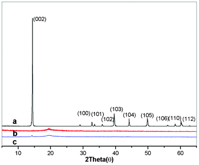 | ||
| Fig. 1 XRD patterns of the MoS2 (a), pure PVA (b) and PVA3 nanocomposite (c). | ||
Fourier transform infrared is an effective technique for evaluating the dispersion of clay in polymeric systems,50–52 as a supplementary technique to XRD and TEM. The condensed-phase products of inorganic MoS2, pure PVA and its composite (PVA3) were characterized by FTIR (Fig. 2). It can be observed that the FTIR spectra of the nanocomposites (PVA3) are very similar to that of pure PVA. In the spectrum of the pure PVA, the broad and strong absorption at 3000–3700 cm−1 is attributed to the symmetrical stretching vibration of hydroxyl in PVA. The peaks at 2800–3000 cm−1 are due to –CH2 and the bands at 1000–1200 cm−1 are attributed to the stretching vibration of C–O.42 As for the MoS2, water bonding at 1632cm−1and O–H stretching broad band center at 3441cm−1 can be observed. From the analysis of FTIR spectra of the PVA3, the characteristic peaks of both the MoS2 and PVA matrix are identified in the spectra of the composite (PVA3). The FTIR assignments indicate that MoS2 has been incorporated into the PVA matrix successfully. Moreover, the frequency shift appeared apparently as seen in Fig. 2b which is induced by the partial exfoliation of the layered MoS2 in the PVA-based composites,50–52 and it means a good dispersion of the MoS2 in the PVA matrix and strong interfacial adhesion between the MoS2 nanosheets and the PVA molecular chains.
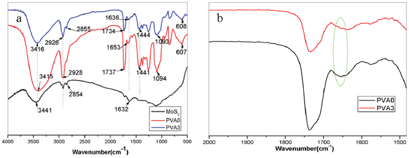 | ||
| Fig. 2 FTIR spectra of the MoS2, pure PVA and PVA3 nanocomposite. | ||
Although the XRD and the FTIR spectrum had shown the dispersion of MoS2 in the PVA3 nanocomposite, more direct information could be observed by TEM. A TEM micrograph of the PVA3 nanocomposite is presented in Fig. 3. It is clearly visible that the MoS2 sheets are randomly dispersed in the PVA matrix, providing direct evidence of crystal layer exfoliation. TEM images also show some large ordered parts, which look like MoS2 layers aggregated together; these may be the reason for the small (002) peak appearing in the XRD pattern of the PVA3. These demonstrate that MoS2 is well dispersed in the PVA matrix with a partial exfoliation structure by simple ultrasonic solvent-casting technique. Therefore, based on the XRD, FTIR results and TEM observation, it can be concluded that a partial exfoliation structure is formed in the case of the PVA3 nanocomposite.
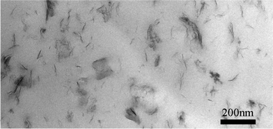 | ||
| Fig. 3 TEM observations of the ultrathin sections obtained from PVA3. | ||
3.2 Thermal behavior of the nanocomposites
As is known to all, incorporation of 2D layered materials usually improves the thermal stability, glass transition temperature (Tg) and fire resistance of polymer nanocomposites, because 2D layered materials can reduce the heat conduction and limit the motions of polymer chains. TGA is one of the most widely used techniques for rapid evaluation of the thermal stability for various polymers. The thermal stability of MoS2, PVA and PVA nanocomposites were evaluated by TGA under air atmosphere, as shown in Fig. 4. The thermal decomposition of MoS2 is plotted in Fig. 4a. The total weight loss of MoS2 is 11 wt% when it is heated to 700 °C. This value is close to the weight loss of the sulfur dioxide molecules (10 wt%), and it means that the MoS2 transforms to molybdenum oxide and sulfur dioxide under air atmosphere in heating process. The thermal decomposition of the PVA and PVA nanocomposites are plotted in Fig. 4b. The temperatures corresponding to 5 and 10 wt% weight loss (T−5% and T−10%) which are used to evaluate the decomposition of PVA on the onset stage and 50 wt% weight loss (T−50%) are also reported in Table 2. The decomposition of PVA occurs in three steps. In the first stage, PVA loses about 5 wt% before 240 °C through primary decomposition and the release of absorbed water because PVA is a hydrophilic polymer. The mass loss at 220–320 °C (about 50 wt%) can be assumed to be the degradation of PVA chains and the heating rearrangement of the polyalkene structure to a polyaromatic form.42 The third stage occurs from 360 to 500 °C and is due to dehydration in the PVA chains. The final residual amount of PVA was found to be 5.89 wt%. When MoS2 was introduced, the thermal stability was found to be markedly enhanced. From Table 2, it is summarized that the T−5% and T−10% of almost all the composites are higher than that of pure PVA, except PVA4. With the increasing concentration of MoS2, T−5% and T−10% of the samples are promoted firstly and then decreased at a high concentration of the MoS2 which is ascribable to the MoS2 not being very well dispersed at a high volume of addition. Even so, the T−5% and T−10% of almost all the composites are still higher than pure PVA. It indicates that the presence of MoS2 defers the initial thermal degradation of PVA. When the added amounts of MoS2 are 1 and 3 wt%, T−5% values of the samples are increased to 277 and 281 °C, respectively, which are 19 and 23 °C higher than that of pure PVA and the T−10% values of the samples also increased slightly. For the T−50% of the samples, after adding MoS2, T−50% of the composites with different concentrations of MoS2 are enhanced. It is noticed that when the concentration of MoS2 reaches 10 wt%, T−50% of the composites is 38 °C higher than pure PVA. All in all, although the changing tendencies of T−5%, T−10% and T−50% have some differences, almost all of them show a significant increase after the addition of the MoS2. These results suggest that incorporating MoS2 into PVA would retard the thermal degradation of PVA molecular chains, and the significantly enhanced thermal stability can be attributed to the strong interactions between MoS2 and PVA, such as hydrogen bonding and the physical barrier effect of the MoS2 nanosheets.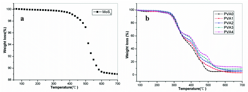 | ||
| Fig. 4 TGA thermograms of MoS2, pure PVA and PVA/MoS2 nanocomposites in air atmosphere. | ||
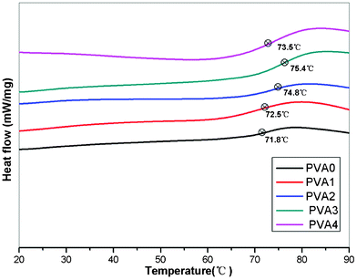
The glass transition temperature (Tg) is an important thermal parameter which can be used to evaluate the segmental mobility of the polymer chains. DSC was carried out to investigate the glass transition process of the PVA nanocomposites. Tg values of the samples above were tested and calculated by DSC. The DSC curves of the prepared samples are presented in Fig. 5, after MoS2 was incorporated, and Tg was found to increase gradually as the MoS2 content increased; it reached the maximum in PVA3, improving by 3.6 °C compared with that of pure PVA. The increase of the Tg is attributed to the great restriction of polymer's chain motions which prove the network and good interfacial interactions between the MoS2 nanosheets and polymer chains. However, we also observed that the Tg started to decrease if the addition of MoS2 exceeded 5%, which may be caused by the poor dispersion of the MoS2 nanosheets.
 | ||
| Fig. 5 DSC curves of PVA nanocomposites marked with glass transition temperature. | ||
3.3 Fire behavior of the PVA nanocomposites
Microscale combustion calorimetry (MCC) is a new technique for investigating the fire resistance properties of materials. MCC can measure the heat release process when very small samples (5–10 mg) are heated in a combustor. It directly measures the heat release of the combusted gases evolved during controlled heating of the samples. The peak of heat release rate (pHRR) is one of the most important parameters to evaluate fire safety. The heat release capacity (HRC) is a good predictor of the heat release rate (HRR) and the propensity for combustion; a low value of HRC is an indication of low flammability and low full scale fire hazard.54 The MCC results for the PVA and its composites are shown in Fig. 6 and Table 3. Compared with neat PVA, the PVA nanocomposites achieved significant improvements in flame resistance. In Fig. 6, the HRR curves of PVA and its composites are composed of three steps, which indicate the decomposition process of the composite. From Fig. 6 and Table 3, the pHRR and HRC of all the PVA composites are lower than pure PVA and decrease gradually as the concentration of the additives increases, except for the PVA4. Both pHRR and HRC show the lowest value when the concentration of MoS2 reaches 5 wt%, compared with the pure PVA, the pHRR and THR decreased apparently, falling by 33% and 20%, respectively. However, as the proportion of MoS2 further increases, PVA4 with 10 wt% MoS2 possesses the higher pHRR and HRC than the PVA3, though it remains lower than that of PVA0. It also may be caused by the poor dispersion at high concentration of the MoS2 as well as the TGA and DSC results. These results above show that MoS2 loadings are beneficial at retarding the combustion of PVA especially at 5 wt% additive amount, which is coincident with the TGA and DSC results.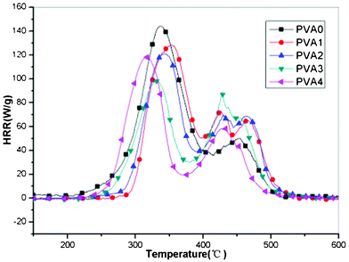 | ||
| Fig. 6 HRR curves of pure PVA and PVA/MoS2 composites. | ||
| Sample | HRC (J g−1 K) | THR (kJ g−1) | pHRR (W g−1) |
|---|---|---|---|
| PVA0 | 147 | 15.9 | 145 |
| PVA1 | 129 | 15.4 | 130 |
| PVA2 | 121 | 14.4 | 121 |
| PVA3 | 98 | 12.8 | 98 |
| PVA4 | 119 | 12.5 | 119 |
From the results of TGA, DSC and MCC test, we can easily find the similar changing trend: incorporation of MoS2 in PVA can effectively improve the thermal properties and the glass transition temperature (Tg), decreased the pHRR and the HRC value. To explain the significant advantages of PVA/MoS2 composites at 5 wt% additive amount, we investigate the residues of the composites after thermal degradation in air atmosphere and the corresponding SEM images of the char residue are shown in Fig. 7. The PVA0, PVA1 and PVA3 are calcined in a muffle furnace in air at 600 °C for 20 min. We find that there are obvious large holes left after thermal degradation of pure PVA, after addition of MoS2, the residues of PVA1 and PVA3 composites become more compact, especially for the PVA3. It means that the addition of the MoS2 result in the formation of carbonaceous char during the thermal degradation. Moreover, it is very interesting to observe many bubbles on the surface of the char residue for the PVA nanocomposites, especially in PVA3 with 5 wt% MoS2. It can be a sign of incombustible gas released in the heating process, in accordance with the TGA results that sulfur dioxide were released in thermal degradation of the MoS2, the released incombustible gases could dilute the concentration of the combustible gas and finally improve the flame retardant performance. The reason for this is that the dense char layer will provide a good barrier to prevent the transfer of heat and volatiles, resulting in significant improvement of the thermal stability and flame retardance of the PVA/MoS2 nanocomposites.53
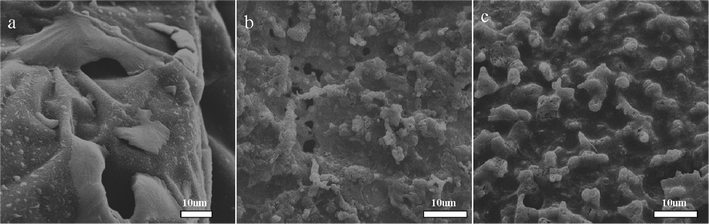 | ||
| Fig. 7 SEM images of surface morphology of the residue of PVA/MoS2 composites after calcination at 600 °C for 20 min in air: a) PVA0; b) PVA1; c) PVA3. | ||
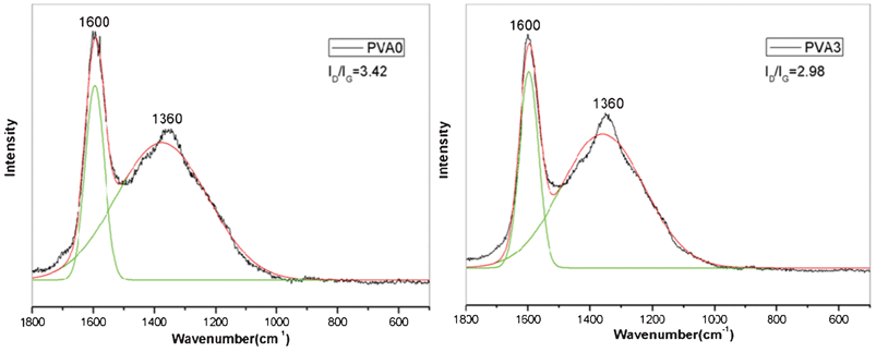
LRS is then used to verify the existence of carbonaceous char in the residue and analyze the specific component of the char. The freshly-made residues of sample PVA0 and PVA3 after the calcination at 600 °C for 20 min in muffle furnace are used directly without acid treatment. From the Raman spectra of the residue (Fig. 8), the spectra in all cases exhibit two broad and strongly overlapping peaks with intensity maxima at about 1600 cm−1 and at about 1380 cm−1 which indicates the char structures. The former band (called the G band) corresponds to the stretching vibration mode with E2g symmetry in the aromatic layers of the graphite crystalline, whereas the latter (called the D band) represents disordered graphite or glassy carbons.54 As shown in Fig. 8, each spectrum was subjected to peak fitting using the curve fitting software Origin 8.0/Peak Fitting Module to resolve the curve into 2 Gaussian bands. The graphitization degree of the char can be estimated by a ratio of the intensity of the D and G bands (ID/IG), where ID and IG are the integrated intensities of the D and G bands, respectively. Basically, the lower the ratio of ID/IG, the better the structure of the char is. According to Fig. 8, the ID/IG ratio follows the sequence of PVA 3(2.98) < PVA0 (3.42), indicating a higher graphitization degree and the most thermally stable char structure of the PVA3.55 The graphitized char formed during thermal degradation is very important in the control of heat spreading and the amount of volatiles because they are very stable at high temperature. The result of LRS confirms the graphitization degree of the residual char of the PVA3 is higher than PVA0, which caused the improvement of the thermal properties and fire resistance of the composites.
 | ||
| Fig. 8 Raman curve of the residue of PVA (PVA0) and PVA/MoS2 nanocomposite (PVA3) after calcination at 600 °C for 20 min in air. | ||
3.4 Mechanical properties
According to the literature, the mechanical performance of the nanocomposites could be enhanced by the rigid LDH layered nanocrystals in PVA matrix. Therefore, it is speculated that the addition of the MoS2 nanosheets will improve the mechanical performance of the PVA nanocomposites. In this work, tensile tests and DMA were carried out to evaluate the mechanical properties (Table 4). The mechanical properties of the PVA nanocomposites are significantly increased compared to those of the neat PVA except the PVA4. The incorporation of MoS2 increases the tensile strength of PVA nanocomposites with low addition (≤5 wt%). The largest increase in tensile strength was 24% in PVA3 (Table 4). This may come from the reinforcing effect of the MoS2 nanosheets at low loading which attributed to the strong interaction between the MoS2 layer and PVA molecular chains. However, high MoS2 loading resulted in poor dispersion which deteriorates the mechanical properties of the composites.| Sample | Tensile strength (MPa) | Elongation at break (%) | Storage modulus at 40 °C (MPa) |
|---|---|---|---|
| PVA0 | 84(±3) | 252(±7) | 5150 |
| PVA1 | 85(±2) | 174(±7) | 6589 |
| PVA2 | 92(±2) | 161(±10) | 5000 |
| PVA3 | 105(±2) | 150(±7) | 5215 |
| PVA4 | 68(±2) | 80(±6) | 4036 |
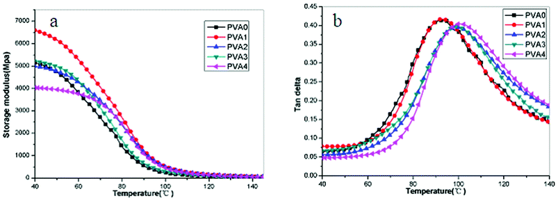
Storage modulus curves (a) and loss angle tangent (b) of are shown in Fig. 9. The storage modulus is a measure of the stiffness, and it increased in all of the PVA/MoS2 nanocomposites except for the PVA4. Sample PVA1 had the largest increase (28%) compared with PVA0 at 40 °C. The temperature at maximum of tan δ is usually taken as the glass transition temperature (Tg). In contrast to the pure PVA (PVA0), the Tg of PVA/MoS2 nanocomposites shift to higher temperature except for PVA1 (Fig. 9b). It can be observed that the Tg values of PVA0 and PVA1 almost have no change, maybe due to low addition of the MoS2. When containing high contents of MoS2 fillers, the Tg values of the PVA/MoS2 nanocomposites increased apparently which can be ascribed to the lamellar barrier effect of the nano-flakes restricting the segmental motion of the polymer chains in the nanocomposites. As discussed with the morphology of the sample PVA3, the existence of partially exfoliated layers in the PVA matrix (TEM Figure) clearly reinforces the PVA matrix and reflects into the tensile strength, modulus values and the temperature at maximum of tan δ (Tg). The homogeneous dispersion of the MoS2 nanolayers at low concentration and the strong interactions between nanolayers and PVA molecular chains explain the observed increase.
 | ||
| Fig. 9 DMA curves of PVA nanocomposites as function of MoS2 contents. | ||
Conclusion
In this work, to obtain high-performance properties of PVA, MoS2 was incorporated into PVA using a novel synthesis strategy based on exfoliation of MoS2, ultrasonic solvent blending, and casting. The morphology, thermal behavior, fire behavior and mechanical properties of the PVA/MoS2 nanocomposites have been studied. XRD, FTIR and TEM results demonstrated that the MoS2 were well dispersed in PVA matrix at 5 wt% loading. The MoS2 nanolayers were homogeneously dispersed in the PVA matrix and resulted in various property enhancements. The thermal stability and fire resistance were significantly improved. The initial degradation temperature (T−5%) of the PVA2 was increased by 23 °C and T−50% of the PVA4 was increased by 38 °C, the Tg of the PVA3 was improved 3.6 °C. Meanwhile, the peak of heat release rate (pHRR) and total heat release (THR) decreased by 33% and 20%, respectively. The storage modulus was increased by 28%, and the tensile strength was increased by 24% upon addition of 1 wt% and 5 wt% MoS2. As a conclusion, our strategy for preparing high-performance MoS2/PVA nanocomposites is novel and efficient, indicating promising use in academic research and practical applications. More importantly, the water solution blending method opens a new avenue to fabricate MoS2-based nanocomposites of water-soluble polymers scalably and effectively for more extensive applications.Acknowledgements
This work was supported by the National Natural Science Foundation of China (No. 21071138) and National Basic Research Program of China (973 Program) (No.2012CB922002).References
- J. Q. Liu, W. R. Yang, L. Tao, D. Li, C. Boyer and T. P. Davis, J. Polym. Sci., Part A: Polym. Chem., 2010, 48, 425 CrossRef CAS.
- K. Chang, W. X. Chen, L. Ma, H. Li, F. H. Huang, Z. D. Xu, Q. B. Zhang and J. Y. Lee, J. Mater. Chem., 2011, 21, 6251 RSC.
- Y. W. Zhu, S. Murali, M. D. Stoller, K. J. Ganesh, W. W. Cai, P. J. Ferreira, A. Pirkle, R. M. Wallace, K. A. Cychosz, M. Thommes, D. Su, E. A. Stach and R. S. Ruoff, Science, 2011, 332, 1537 CrossRef CAS.
- H. Zhang, X. J. Lv, Y. M. Li, Y. Wang and J. H. Li, ACS Nano, 2010, 4, 380 CrossRef CAS.
- Y. Long, C. C. Zhang, X. X. Wang, J. P. Gao, W. Wang and Y. Liu, J. Mater. Chem., 2011, 21, 13934 RSC.
- V. Eswaraiah, K. Balasubramaniam and S. Ramaprabhu, J. Mater. Chem., 2011, 21, 12626 RSC.
- J. H. Jung, D. S. Cheon, F. Liu, K. B. Lee and T. S. Seo, Angew. Chem., Int. Ed., 2010, 49, 5708 CrossRef CAS.
- Z. Xu and C. Gao, Nat. Commun., 2011, 2, 571 CrossRef.
- L. L. Zhang, R. Zhou and X. S. Zhao, J. Mater. Chem., 2010, 20, 5983 RSC.
- T. Kuilla, S. Bhadra, D. H. Yao, N. H. Kim, S. Bose and J. H. Lee, Prog. Polym. Sci., 2010, 35, 1350 CrossRef CAS.
- J. A. Wilson and A. D. Yoffe, Adv. Phys., 1969, 18, 193 CrossRef CAS.
- X. F. Zhang, B. Luster, A. Church, C. Muratore, A. A. Voevodin, P. Kohli, S. Aouadi and S. Talapatra, ACS Appl. Mater. Interfaces, 2009, 1, 735 CAS.
- Y. Li, H. Wang, L. Xie, Y. Liang, G. Hong and H. Dai, J. Am. Chem. Soc., 2011, 133, 7296 CrossRef CAS.
- B. Radisavljevic, A. Radenovic, J. Brivio, V. Giacometti and A. Kis, Nat. Nanotechnol., 2011, 6, 147 CrossRef CAS.
- X. W. Lou and H. C. Zeng, Chem. Mater., 2002, 14, 4781 CrossRef CAS.
- R. Bissessur, D. Gallant and R. Brüning, Mater. Chem. Phys., 2003, 82, 316 CrossRef CAS.
- R. Bissessur and W. White, Mater. Chem. Phys., 2006, 99, 214 CrossRef CAS.
- B. Z Lin, C. Ding, B. H. Xu, Z. J. Chen and Y. L. Chen, Mater. Res. Bull., 2009, 44, 719 CrossRef.
- K. Chang and W. Chen, ACS Nano, 2011, 5, 4720 CrossRef CAS.
- K. Chang and W. X. Chen, Chem. Commun., 2011, 47, 4252 RSC.
- K. Chang, W. X. Chen, L. Ma, H. Li, H. Li, F. H. Huang, Z. D. Xu, Q. B. Zhang and J. Y. Lee, J. Mater. Chem., 2011, 21, 6251 RSC.
- Z. Matusinovic and C. A. Wilkie, J. Mater. Chem., 2012, 22, 18701 RSC.
- P. Ding, W. Chen and B. J. Qu, Prog. Nat. Sci., 2006, 16, 573–579 CrossRef CAS.
- M. Alexandre and P. Dubois, Mater. Sci. Eng., R, 2000, 28, 1–63 CrossRef.
- S. R. Suprakas and M. Okamoto, Prog. Polym. Sci., 2003, 28, 1539–1641 CrossRef.
- B. M. Alexander, Polym. Adv. Technol., 2006, 17, 206–217 CrossRef.
- S. Pavlidou and C. D. Papaspyrides, Prog. Polym. Sci., 2008, 33, 1119–1198 CrossRef CAS.
- T. Kuilla, S. Bhadra, D. H. Yao, N. H. Kim, S. Bose and J. H. Lee, Prog. Polym. Sci., 2010, 35, 1350–1375 CrossRef CAS.
- R. Verdejo, M. M. Bernal, L. J. Romasanta and M. A. Lopez-Manchado, J. Mater. Chem., 2011, 21, 3301–3310 RSC.
- R. P. Jeffrey, R. D. Daniel, C. W. Bielawski and R. S. Ruoff, Polymer, 2011, 52, 5–25 CrossRef.
- R. Bissessur, M. G. Kanatzidis, J. L. Schindler and C. R. Kannewurf, J. Chem. Soc., Chem. Commun., 1993, 1582–1585 RSC.
- K. E. Dungey, M. D. Curtis and J. E. Penner-Hahn, Chem. Mater., 1998, 10, 2152 CrossRef CAS.
- C. C. Yang, S. J. Chiu and W. C. Chien, J. Power Sources, 2006, 162, 21 CrossRef CAS.
- B. V. K. Naidua, M. Sairam, K. Raju and T. M. Aminabhavi, J. Membr. Sci., 2005, 260, 142 CrossRef.
- S. A. Paralikara, J. Simonsen and J. Lombardi, J. Membr. Sci., 2008, 320, 248 CrossRef.
- A. G. Sullad, L. S. Manjeshwar and T. M. Aminabhavi, J. Appl. Polym. Sci., 2010, 117, 1361 CAS.
- A. A. Sapalidis, F. K. Katsaros, G. E. Romanos, N. K. Kakizis and N. K. Kanellopoulos, Composites, Part B, 2007, 38, 398 CrossRef.
- K. E. Strawhecker and E. Manias, Chem. Mater., 2000, 12, 2943 CrossRef CAS.
- C. L. Bao, Y. Q. Guo, L. Song, H. D. Lu, B. H. Yuan and Y. Hu, Ind. Eng. Chem. Res., 2011, 50, 11109 CrossRef CAS.
- N. Ogata, S. Kawakage and T. Ogihara, J. Appl. Polym. Sci., 1997, 66, 573 CrossRef CAS.
- S. Huang, X. Cen, H. Zhu, Z. Yang, Y. Yang, W. W. Tjiu and T. X. Liu, Mater. Chem. Phys., 2011, 130, 890 CrossRef CAS.
- C. L. Bao, Y. Q. Guo, L. Song and Y. Hu, J. Mater. Chem., 2011, 21, 13942 RSC.
- H. J. Salavagione, G. Martinez and M. A. Gomez, J. Mater. Chem., 2009, 19, 5027–5032 RSC.
- Q. Y. Soundararajah, B. S. B. Karunaratne and R. M. G. Rajapakse, J. Compos. Mater., 2010, 44, 303–311 CrossRef CAS.
- T. M. Wang, W. M. Liu, J. Tian, X. Shao and D. C. Sun, Polym. Compos., 2004, 25, 1 CrossRef.
- M. Naffakh, A. M. Díez-Pascual, M. Remškar and C. Marco, J. Mater. Chem., 2012, 22, 17002–17010 RSC.
- T. Tang, X. C. Chen, X. Y. Meng, H. Chen and Y. P. Ding, Angew. Chem., Int. Ed., 2005, 44, 1517 CrossRef CAS.
- Y. Deng, Y. Z. Wang, D. M. Ban, X. H. Liu and Q. Zhou, J. Anal. Appl. Pyrolysis, 2006, 76, 198 CrossRef CAS.
- B. H. Xu, B. Z. Lin, D.Y. Sun and C. Ding, Electrochim. Acta, 2007, 52, 3028 CrossRef CAS.
- W. L. Ijdo, S. Kemnetz and D. Benderly, Polym. Eng. Sci., 2006, 46, 1031 CAS.
- K. C. Cole, Macromolecules, 2008, 41, 834 CrossRef CAS.
- Spiros Tzavalas and V. G. Gregoriou, Vib. Spectrosc., 2009, 51, 39 CrossRef CAS.
- D. Y. Wang, A. Das, A. Leuteritz, R. N. Mahaling, D. Jehnichen, U. Wagenknecht and G. Heinrich, RSC Adv., 2012, 2, 3927 RSC.
- Y. Y. Dong, Z. Gui, S. H. Jiang, Y. Hu and K. Q. Zhou, Ind. Eng. Chem. Res., 2011, 50, 10903 CrossRef CAS.
- Q. L. Tai, Y. Hu, K. K. Y. Richard, L. Song and H. D. Lu, J. Mater. Chem., 2011, 21, 6621–6627 RSC.
| This journal is © The Royal Society of Chemistry 2012 |