Polymer-directed synthesis of metal oxide-containing nanomaterials for electrochemical energy storage
Yiyong
Mai
ab,
Fan
Zhang
*a and
Xinliang
Feng
*ab
aSchool of Chemistry and Chemical Engineering, Shanghai Jiao Tong University, 800 Dongchuan Road, 200240, Shanghai, P. R. China
bMax Planck Institute for Polymer Research, Ackermannweg 10, 55128, Mainz, Germany. E-mail: fan-zhang@sjtu.edu.cn; feng@mpip-mainz.mpg.de
First published on 25th October 2013
Abstract
Metal oxide-containing nanomaterials (MOCNMs) of controllable structures at the nano-scale have attracted considerable interest because of their great potential applications in electrochemical energy storage devices, such as lithium-ion batteries (LIBs) and supercapacitors. Among many structure-directing agents, polymers and macromolecules, including block copolymers (BCPs) and graphene, exhibit distinct advantages in the template-assisted synthesis of MOCNMs. In this feature article, we introduce the controlled preparation of MOCNMs employing BCPs and graphene as structure-directing agents. Typical synthetic strategies are presented for the control of structures and sizes as well as the improvement of physical properties and electrochemical performance of MOCNMs in LIBs and supercapacitors.
1. Introduction
Human society is confronted with aggravating energy and environmental problems including CO2-related global warming and fossil fuel depletion. Accordingly, great efforts have been made to efficiently use clean and renewable energy sources (solar, wind, geothermal, etc.), for example, the development of eco-friendly and sustainable vehicles, such as electric vehicles (EVs) and hybrid EVs.1–4 The utilization of renewable energy sources generally requires the side support of energy storage that can compensate their intermittent characteristics. As portable energy storage devices, lithium-ion batteries (LIBs) and supercapacitors are the most promising candidates to meet this requirement, owing to their high energy and power densities.1–4 Since the performance of these energy storage devices is strongly governed by the nature of electrode materials, the development of electrochemical materials with high activity and desired structures has been the central research focus in the past decade.1–4Various all-carbon materials, with graphitic or porous structures, have been explored as potential alternatives to graphite anodes in electrochemical energy storage devices.4–6 In addition, a diversity of metal oxides, including SnO2, TiO2, Fe2O3, Co3O4, MnO2, V2O5, and many other transition metal oxides, have also been studied as potential anode materials.7,8 Comparatively, metal oxides possess a number of distinct advantages, including high specific capacity, widespread availability, good stability, and environmental friendliness, among others.7 For example, TiO2 is an attractive anode material because of its ease of structural tailoring, low volume expansion upon lithiation, and a lack of lithium plating. Fe2O3 has been found to have a high theoretical capacity of ca. 1000 mA h g−1, which can be explained by the “conversion reaction” mechanism, namely Fe2O3 + 6Li+ + 6e− ↔ 2Fe + 3Li2O. In addition, these two sorts of metal oxides are of low toxicity, relatively abundant and easy to prepare.7 On the other hand, there are also several drawbacks associated with metal oxide materials, such as relatively large volume variations and poor electrical conductivity.7 Construction of metal oxide–carbon hybrids that combine the attractive properties of the two components is regarded as an effective protocol to overcome the problems and tune the behavior of the resulting materials for enhanced device performance.6–8 In this review, pure metal oxide materials and metal oxide–carbon hybrids with structural features at the nanometer scale are referred to as metal oxide-containing nanomaterials (MOCNMs).
Two primary pathways, namely template-assisted and template-free approaches, are generally applied for the synthesis of MOCNMs.7,8 The template-assisted methods are favorable for the control of morphology and size, which are essential to achieve high performance for MOCNMs.7 Many structure-directing agents have been developed for the template-assisted synthesis of MOCNMs,9 including small-molecule surfactants,10 block copolymers (BCPs),11–13 organogels,14 silica nanostructures,15 nanocrystals,16 carbon nanotubes,17 graphene,2,4,18–21etc. Among these structure-guiding agents, BCPs provide a unique platform for structuring materials with versatile morphologies and tunable sizes,11–13 because they may self-assemble into robust and controllable nanostructures depending on the copolymer composition, the used solvent, the presence of additives such as ions, and so on.22 Also, BCPs are easy to be removed from mineral frameworks by calcination or solvent extraction.11–13 Therefore, BCPs represent a desired structure-guiding candidate for the fabrication of porous electrode materials, which provide a high surface area for intimate contact with the electrolyte and short diffusion paths for ionic transport and electronic conduction.12,13 On the other hand, graphene, a single-layer graphite with close-packed conjugated hexagonal carbon lattices, is well-known as a type of two-dimensional (2D) polymers with high electrical conductivity, large specific surface area, high theoretical lithium storage capacity (744 mA h g−1 for single-layer graphene) and large specific capacitance (∼135 F g−1 for single-layer graphene).2,4,18–21 However, single-layer graphene nanosheets always stack into multilayers and therefore lose their high surface area and intrinsic chemical and physical properties.2,4,18–21 Controlled incorporation of metal oxides onto graphene, forming graphene–metal oxide hybrids, may simultaneously stabilize graphene from aggregation and combine the advantages of the two components. The synergistic effects between graphene and metal oxides in the composites can result in considerable increases in lithium storage capacity, specific capacitance, and reversible charging/discharging capability, compared with those of individual graphene or metal oxides.2,4,18–21
In view of the significant roles of polymers in the preparation of MOCNMs for energy storage applications, this feature article focuses on the controlled synthesis of MOCNMs using BCPs (in Section 2) and graphene (in Section 3) as typical structure-directing agents, respectively. In each section, representative examples are presented jointly. The final section provides the summary and outlook.
2. Block copolymers as structure-directing agents
2.1. Self-assembly of block copolymers
BCPs consist of two or more chemically distinct polymer blocks covalently bound together. Generally, these blocks are thermodynamically immiscible with each other as the entropy of mixing per unit volume is small and varies inversely with molecular weight. In bulk, BCPs, e.g. diblock copolymers, can microphase separate as a function of composition into a variety of morphologies, including body-centered-cubic spheres (S), hexagonally packed cylinders (C), bicontinuous gyroids (G), lamellae (L), etc. (Fig. 1).22,23 The self-assembly of BCPs is driven by an unfavorable mixing enthalpy coupled with a small mixing entropy, with the covalent bond connecting the blocks preventing macroscopic phase separation. The microphase separation of diblock copolymers depends on three parameters: (1) the volume fractions of the A and B blocks (fA and fB, with fA + fB = 1), (2) the total degree of polymerization (N = NA + NB), and (3) the Flory–Huggins interaction parameter (χAB). The χAB parameter varies inversely with temperature and specifies the degree of incompatibility between the A and B blocks, which drives the phase separation. The degree of microphase separation of diblocks is determined by the segregation product, χABN. In terms of the self-consistent mean-field (SCMF) theory, if χABN is larger than ca. 10.5, microphase separation occurs and the predicted morphologies as a function of volume fraction (f) of one block with respect to the other have been summarized in a theoretical phase diagram (Fig. 1).22,23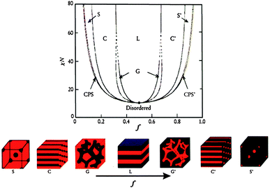 | ||
| Fig. 1 Theoretical phase diagram of diblock copolymers in bulk predicted by the self-consistent mean-field theory and the equilibrium morphologies depending on volume fraction (f) of one block to the other and the segregation parameter, χN, where χ represents the Flory–Huggins segment–segment interaction energy and N is the degree of polymerization. CPS and CPS′ = closely packed spheres, S and S′ = body-centered-cubic spheres, C and C′ = hexagonally packed cylinders, G and G′ = bicontinuous gyroids, and L = lamellae.22,23 The figures are reproduced with permission from ref. 22. | ||
Compared with the self-assembly of BCPs in bulk, the self-assembly of BCPs in solution shows an increased level of complexity and produces diverse assemblies including a range of morphologies similar to those observed in bulk, namely spherical micelles, cylindrical micelles, bicontinuous structures, lamellae, vesicles (closed lamellae), etc.22 More complex aggregate structures, such as lyotropic liquid crystalline phases, can be formed at high polymer concentrations.24 The morphologies and sizes of the BCP assemblies can be controlled by many factors, including the copolymer composition and concentration, the content of precipitant, the nature of the solvent, the presence of additives such as ions or homopolymers, among others.22 Experimental phase diagrams have been plotted for a number of BCP systems, such as polystyrene-block-poly(acrylic acid) (PS-b-PAA),25 polybutadiene-block-poly(ethylene oxide) (PB-b-PEO),26 polyisoprene-block-PEO (PI-b-PEO),27 PEO-block-poly(propylene oxide)-block-PEO (PEO-b-PPO-b-PEO),28 and so on.
Solvent evaporation of BCP solutions can result in the formation of BCP thin films or monoliths, with or without the assistance of cast-, dip-, or spin-coating of the BCP solutions on solid substrates. The morphologies generated in BCP thin films or monoliths by the evaporation-induced self-assembly (EISA) of BCPs are parallel to those in bulk. The morphologies can also be tuned by the factors analogous to those described above for BCPs in bulk or in solution.29
2.2. From block copolymers to ordered metal oxide nanostructures
The concept of BCP self-assembly was first utilized to build up highly ordered nanostructured porous silica in 1995 by the Pinnavaia group using low-molecular-weight BCPs as templates,30 and later expanded by several other groups employing high-molecular-weight BCPs.24,31,32 Following the pioneering work on nanostructured silica, BCPs were used as structure-guiding media for the preparation of nanostructured metal oxide-containing porous materials.33,34 A general synthetic strategy is the soft-templating method. This approach usually involves three primary steps, as illustrated in Fig. 2.11 (1) The cooperative self-assembly of inorganic sol–gel precursors (e.g. metal alkoxides or salts) with amphiphilic BCPs. This process generates a microphase separation, dividing the mixture into hydrophilic and hydrophobic domains. (2) The formation of an inorganic network caused by condensation reactions of the inorganic precursors. These reactions can be tuned to take place simultaneously or subsequently as the self-organization proceeds. (3) Elimination of the BCP template can be realized by calcination or solvent extraction. In this step, crystalline metal oxides may form during calcination, depending on the applied temperature.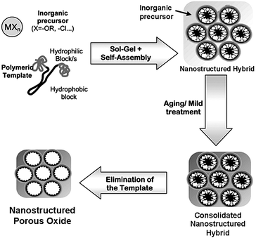 | ||
| Fig. 2 Schematic illustration of the preparation of nanostructured porous oxides using amphiphilic block copolymers as the structure-directing agents. Reproduced with permission from ref. 11. | ||
The soft-templating strategy using BCPs renders opportunities for the control of the structure, pore size, wall thickness and/or surface area of resultant porous nanostructures. The structure is influenced by the rational control of organic–inorganic interaction and cooperative assembly of inorganic precursors and BCPs. Aside from the factors affecting the morphology of BCP assemblies mentioned in Section 2.1, the volume ratio of BCP to inorganic precursor is also a crucial factor for the formation of ordered porous nanostructures. For example, Stucky, Chmelka and collaborators prepared mesoporous TiO2 films with body-centered cubic, hexagonal, and lamellar structures by changing the volume ratio of the PEO20-b-PPO70-b-PEO20 copolymer (Pluronic P123) to the Ti precursor in the initial solution.35 They defined a volume fraction (Φ) of the copolymer to explain the morphological control of the nanostructures: Φ = Vpol/(Vpol + Vinorg), where Vpol presents the volume of the copolymer and Vinorg denotes the volume of the inorganic components in the solution. The body-centered cubic mesophase is formed at a low concentration of the copolymer with Φ = 29–36%, the hexagonal nanostructure is obtained at Φ = 38–55%, whereas the lamellar structure is formed at a higher concentration with Φ = 61–75%. The pore size of porous structures mainly depends on the hydrophobic volumes of BCPs. The BCP assemblies are much larger than those aggregates formed by low-molecular-weight surfactants, and thereby lead to much larger pore sizes. For instance, mesoporous TiO2 templated by Pluronic P123 has a pore size of 6.5 nm.33 The pore size can be adjusted by adding a swelling agent. Studies have shown that the pore size of mesoporous TiO2 films templated by Pluronic P123 increases up to 20 nm with increasing amounts of the swelling agent, poly(propylene oxide).36 In addition, the calcination process also influences the pore size due to the shrinkage of the frameworks at high temperature; the pore size usually decreases with the increase of the calcination temperature. The wall thickness of porous structures depends on the length of the hydrophilic segments of BCPs. Triblock copolymers can yield thick walls of 3–7 nm and diblock copolymers can even produce much thicker walls.13 The influence of the calcination temperature on the wall thickness is similar to the trend of pore size. The surface area is mainly dependent on the temperature of the heat treatment or calcination.13 Solvent extraction or heat treatment at a low temperature (<200 °C) can give rise to a high surface area up to 700–1000 m2 g−1, while after calcined at a high temperature (300–500 °C), the surface area decreases sharply to 100–400 m2 g−1. Crystallization is usually required for metal oxide nanostructures to improve their capacities of charge storage and electron conduction. The crystallinity of metal oxides is mainly determined by the calcination temperature. Semicrystalline metal oxides (e.g. TiO2) with small nanocrystals embedded in an amorphous matrix can be obtained by calcination at around 350–450 °C, whereas higher temperature (over ∼500 °C) can improve the crystallinity of metal oxides.13
The techniques employed in the soft-templating strategy for the preparation of porous nanostructures mainly include precipitation-based,32 liquid crystal templating,24 evaporation-induced self-assembly (EISA),37 solvothermal methods,38etc. The EISA is currently the most widely used approach for the synthesis of metal oxide-containing porous materials. By this means, the cooperative self-assembly of inorganic sol–gel precursors with amphiphilic BCPs (the first process in Fig. 2) is induced by solvent evaporation. Starting from dilute solutions below the critical micellar concentration allows the formation of ordered liquid-crystalline mesophases in thin films or monoliths with excellent homogeneity.37 This method facilitates the control of the hydrolysis and polycondensation of metal precursors (e.g. titania precursors) and has been developed practically for a wide range of metal oxides.39
Yang et al. did pioneering work on the preparation of mesoporous metal oxides.33,34 They used inorganic chloride salts (MCl) as precursors and amphiphilic poly(alkylene oxide) BCPs as structure-directing agents in non-aqueous solutions. The sol solution was gelled in an open Petri dish at 40 °C in air for 1–7 days, during which the inorganic precursor formed a metal oxide network. Alternatively, the sol solution was used to prepare thin films by dip-coating. The as-prepared bulk samples or thin films were then calcined at 400 °C in air to remove the BCP templates. Many thermally stable, ordered, mesoporous (large pore up to 14 nm) metal oxides with 2D hexagonal or 3D cubic structures were obtained (Fig. 3), including TiO2, ZrO2, Nb2O5, Ta2O5, WO3, SnO2, Al2O3, and many mixed metal oxides. For example, they employed TiCl4 and Pluronic P123 to prepare mesoporous TiO2 with a 2D hexagonal structure (Fig. 3a and b), which had a surface area of 205 m2 g−1 and a pore size of 6.5 nm. The mesoporous TiO2 contained some nanocrystalline domains within the relatively thick amorphous walls. During the synthetic process, however, the lack of water which was provided only by air moisture and impurities made the hydrolysis and polycondensation of the TiCl4 very slow, leading to a long aging time of 7 days. After this pioneering work, many studies have been conducted on the synthesis of porous metal oxides.13,40 Many distinct improvements have been made on the synthetic routes, structural regularity, surface area, crystallinity, etc. Due to space limitations in this feature article, we selectively introduce several typical examples below.
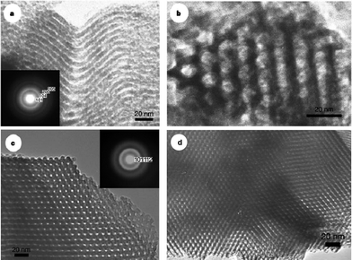 | ||
| Fig. 3 Transmission electron microscopy (TEM) micrographs of 2D hexagonal mesoporous TiO2 (a and b), ZrO2 (c), and Nb2O5 (d). Insets in a and c are selected-area electron diffraction patterns obtained on the image area. The figures are reproduced with permission from ref. 33. | ||
Zhao and colleagues developed an “acid–base pair” route for the synthesis of highly ordered mesoporous metal oxides.41,42 This method improved the structural regularity of mesoporous metal oxides and greatly shortened the synthetic period. For instance, they prepared highly ordered hexagonal mesoporous TiO2 using a mixture of titanium alkoxide and TiCl4 as the precursors and Pluronic P123 as the template. The obtained mesoporous TiO2 has a large uniform pore size of ∼4 nm and a high surface area of ∼240 m2 g−1. The titanium alkoxide, acting as a main source, is an extra oxygen donor and thus makes the cross-linkage and gelation of Ti precursors much easier. TiCl4 acts as an acidity adjustor and a hydrolysis-condensation controller. The acidity of the precursor solution is reduced by decreasing the amount of TiCl4. The aging time is remarkably shortened to 2 days. This approach provides an important guidance for the selection of precursors in the synthesis of a variety of mesoporous metal oxides or mixed oxides.42
Sanchez and co-workers systematically synthesized highly organized and oriented mesoporous titania thin films by an EISA dip-coating method, using poly(ethylene oxide) (PEO)-based templates including PEO-b-PPO-b-PEO copolymers.43 Crack-free titania thin films with high surface area (>100 m2 g−1) and tailored mesostructures (wormlike, cubic, and hexagonal) were readily prepared, through the adjustment of six affecting factors including the type of the template, the template/Ti ratio, the water content inside the solution, the relative humidity in the atmosphere, the solution acidity, and the temperature during deposition and aging.
Ozin's group developed a “one-pot low temperature” approach towards the synthesis of crack-free thin films of nanocrystalline titania.44 This method involves hydrothermal treatment of 1-butanol solution of the titanium butoxide precursor and Pluronic P123 at 100 °C, followed by EISA to give a thin film, which is subsequently subjected to thermal treatment at 120 °C to attain the full condensation of the TiO2 framework; the BCP template is then removed by exposing the thin film to UV irradiation. The whole process of the titania film fabrication is performed at temperatures of less than 120 °C and thereby allows the use of substrates which are not tolerant at high temperatures. The TiO2 film has a highly ordered 2D hexagonal structure with a pore size of ca. 7 nm and a wall thickness of ca. 4 nm (Fig. 4a–c). The film is crack-free and is easily bent without any damage (Fig. 4d).
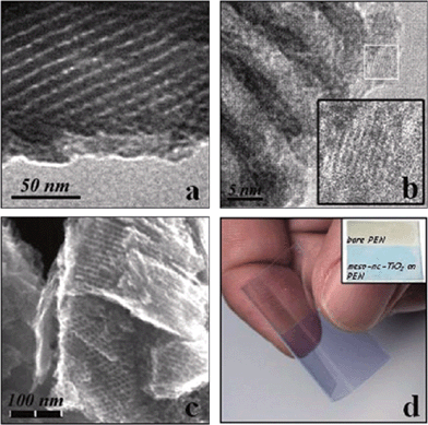 | ||
| Fig. 4 TEM (a and b) and scanning electron microscope (SEM, c) images obtained from the TiO2 film and a photograph (d) of a flexible crack-free mesostructured nanocrystalline TiO2 film, which was deposited on a polyethylene naphthalate (PEN) substrate and dyed with methylene blue. The figures are reproduced with permission from ref. 44. | ||
In addition to Pluronic copolymers (PEO-b-PPO-b-PEO), other BCPs can also serve as structure-guiding agents, such as PHB-b-PEO (PHB = hydrogenated poly(butadiene), this polymer is named as KLE),40,45–48 polyisobutylene-b-PEO (PIB-b-PEO),49 polyisoprene-b-PEO (PI-b-PEO),50 PS-b-PEO,51 poly(methyl methacrylate)-b-PEO (PMMA-b-PEO),52etc. Compared with the Pluronic copolymers, these BCPs have higher hydrophobic contrasts, leading to fast micellization and sufficient mesophase formation early in the sol process and thereby constructing more robust templates to support metal oxide gel structures during heat treatment. Therefore, porous metal oxide materials with large pores, high levels of order, high crystallinity and stability can be synthesized with the use of these BCPs as templates. For example, Smarsly and Grosso et al. prepared highly crystalline cubic mesoporous TiO2 by employing KLE copolymers.45 The pore size is about 10 nm, which is larger than ordered TiO2 nanostructures templated by the Pluronic copolymers. The complete crystallization upon template removal and the good stability of the final porous TiO2 were achieved by a straight thermal treatment instead of a complex temperature program which is needed to avoid a structure collapse in the general preparation of mesoporous TiO2 templated by the Pluronic copolymers. The larger pore sizes, higher crystallinity and stability of the resultant TiO2 are attributed to the enhanced hydrophobic attraction between the hydrophobic PHB chains compared with the Pluronic copolymers.45
The KLE copolymers are particularly suitable for the directed synthesis of ordered mesoporous metal oxide films with highly crystalline walls.40,47 Part of the reason is the formation of an inorganic–organic composite with sufficiently thick pore walls that can be highly crystallized. Brezesinski et al. prepared cubic mesoporous α-MoO3 thin films with iso-oriented crystalline walls using KLE copolymers as templates (Fig. 5).47 The thin films have an average pore diameter of 13 nm and a surface area of ∼200 m2 g−1. They characterized capacitive charge storage in the mesoporous α-MoO3 thin films and demonstrated that these films show enhanced pseudocapacitance compared with both mesoporous amorphous and non-templated crystalline MoO3 (Fig. 5). Their results indicated that redox pseudocapacitance benefits from the mesoporous morphology by enabling electrolyte access to the electrochemical sites and short diffusion path lengths. Furthermore, intercalation pseudocapacitance, i.e., the insertion of Li+ in the quasi-2D planes of the crystalline α-MoO3, takes a major responsibility for the high capacitive charge storage.47
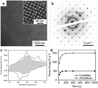 | ||
| Fig. 5 (a) TEM micrograph of the mesoporous α-MoO3 thin films; inset: a higher magnification micrograph. (b) Selected-area electron diffraction pattern showing diffraction spots characteristic of iso-oriented molybdite oriented along the (110) direction. (c) Voltammetric responses for mesoporous α-MoO3 films at a sweep rate of 0.1 mV s−1. The capacitive contribution to the total current is shown by the shaded region. (d) The capacitance of the mesoporous crystalline α-MoO3 films is three times larger than that of the mesoporous amorphous MoO3. The figures are reproduced with permission from ref. 47. | ||
Apart from using metal alkoxides or salts as the sol–gel precursors in the soft-templating method presented in Fig. 2, porous crystalline metal oxide nanostructures can also be prepared by employing preformed nanocrystals as the self-assembly precursors.40,48,53,54 The use of preformed nanocrystals can produce small pores among the nanocrystals in the wall in addition to the large pores templated by BCPs, thereby leading to bimodal porosity of the resultant metal oxide nanostructures. Brezesinski et al. prepared anatase TiO2 thin films templated by KLE copolymers using either TiCl4 sol–gel reagents (referred to as KLE-templated sol–gel films) or preformed TiO2 nanocrystals (referred to as KLE-templated nanocrystal films) as building blocks.48 Both materials are highly crystalline. However, the KLE-templated sol–gel films show a monomodal pore structure, while the KLE-templated nanocrystal films own bimodal porosity which generates high surface area (Fig. 6a–d). Pseudocapacitive characteristics obtained from cyclic voltammetric data demonstrate that both materials have high capacities of charge storage and Li+ insertion. In contrast, the charging/discharging rates, the lithium storage capacity and the capacitance improve apparently for the templated nanocrystal films (Fig. 6e–g). The results can be attributed to the bimodal porosity, with larger mesopores allowing for electrolyte diffusion and smaller micropores exposing many redox active sites on the surface of the TiO2 to the electrolyte.48
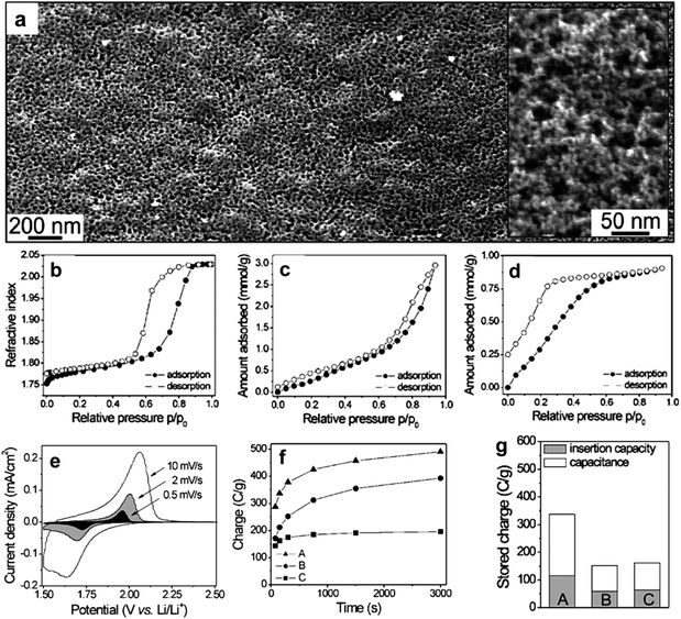 | ||
| Fig. 6 (a) Low magnification top-view FESEM images of a mesoporous KLE-templated nanocrystal TiO2 film. The inset in (a) shows a high magnification top-view FESEM image; the porosity is bimodal with 1–4 and 20–25 nm diameter pores. (b–d) Toluene adsorption–desorption isotherms for self-organized TiO2 thin films: (b) KLE-templated sol–gel films showing a monomodal pore structure; (c) KLE-templated nanocrystal films with bimodal porosity; (d) untemplated nanocrystal films with <4 nm pores formed by random nanocrystal aggregation. (e) Typical cyclic voltammetric responses of KLE-templated nanocrystal films at various sweep rates. (f) Comparison of charging rates calculated from cyclic voltammetric data at various sweep rates. (g) Comparison of the total stored charge. For f and g plots, A and C refer to KLE-templated and untemplated nanocrystal films, respectively, while B refers to KLE-templated sol–gel films. The figures are reproduced with permission from ref. 48. | ||
Another noteworthy “soft-templating” method is the use of preformed BCP micelles as templates for the preparation of metal oxide nanostructures. This approach is analogous to the one using polystyrene beads as templates, which is often applied for the fabrication of hollow inorganic oxide particles.55–57 Nakashima and colleagues first employed the poly(styrene-b-2-vinyl-1-methylpyridinium iodide-b-ethylene oxide) (PS-b-PVMP-b-PEO) copolymer to form polymeric micelles with a PS core, a PVMP shell and a PEO corona in aqueous solution.58,59 The PS core acts as a template of the cavity; the quaternized PVP shell, i.e. the PVMP shell, works as a reservoir and nanoreactor for the metal oxide precursors, e.g. niobium(V) ethoxide, cerium sulfate, and ammonium vanadate(V), while the PEO corona helps to stabilize the polymer–metal oxide hybrid nanoparticles (NPs) in solution and prevent their aggregation. After the sol–gel process of metal oxide precursors in the PVMP shell of the micelles and the removal of the polymer template by calcination at 500 °C, hollow metal oxide spheres (Nb2O5, CeO2, and V2O5) are obtained.59 The hollow spheres have uniform cavity sizes and wall thicknesses, which are tunable by varying the lengths of the PS block and the PVMP block of the triblock copolymer, respectively.
Although in some cases the soft-templating methods produce crystalline metal oxides, such materials are often not fully crystalline and structural collapse occurs frequently during heat treatment over 500 °C. For some metal oxides such as Nb2O5, heat treatment to a temperature higher than 500 °C is required to obtain high crystallinity, which favors the electron transport in lithium batteries.50 Thus, it remains a challenge to synthesize highly crystalline metal oxides. On the other hand, the use of hard templates such as mesoporous silica or carbon (the hard-templating methods) allows for the accessibility to high crystallinity as the hard templates can prevent structural collapse at high temperature.60 However, the synthetic routes for the hard-templating methods are often long and tedious. Furthermore, it is difficult to achieve the morphological variability of metal oxides by the hard-templating methods using the same precursors and templates. In order to overcome the limitations of the soft- and hard-templating methods, Wiesner's group developed an elegant one-pot approach, referred to as the combined assembly by the soft and hard (CASH) method, for the fabrication of metal oxide nanostructures with high stability and crystallinity.12 They employed PI-b-PEO copolymers as structure-directing agents to fabricate mesoporous TiO2 and Nb2O5 (Fig. 7a).50 The PI segments containing sp2 hybridized carbon atoms were converted in situ to an amorphous-graphitic carbon material when being heated under an inert atmosphere. The generated carbon acted as an in situ-type hard template, preventing structural collapse while allowing the conversion of metal oxides from amorphous to crystalline. Thus, such metal oxides could undergo a heat treatment of up to 700 °C under argon to achieve high crystallinity. After the removal of the carbon by calcination in air at ca. 450 °C, highly stable and crystalline mesoporous metal oxides were obtained. A limitation of the CASH method is the requirement of an sp2 hybridized segment for the BCP templates. Zhao and co-workers reported a simple surfactant-sulphuric-acid carbonization method to synthesize highly crystalline mesoporous TiO2 using Pluronic triblock copolymers which do not contain sp2 hybridized carbon atoms and are commercially available (Fig. 7b).61 Before calcination, the copolymer template was first carbonized by H2SO4 to form amorphous carbon, which supported the TiO2 framework in the course of crystallization at high temperatures (550 and 650 °C). After the burning out of the carbon in air at 450 °C, ordered 2D hexagonal mesoporous TiO2 with a fully crystalline framework was achieved.
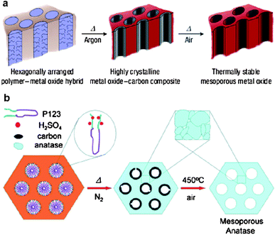 | ||
| Fig. 7 Schematic illustrations of the CASH method50 (a) and the surfactant-sulfuric-acid carbonization method61 (b). The figures are reproduced with permission from ref. 50 and 61. | ||
Apparently, one can see in Fig. 7 that porous carbon–metal oxide hybrids can also be synthesized following similar synthetic strategies. The motif is thus shifted to the preparation of porous carbon–metal oxide composites, as described in Section 2.3.
2.3. From block copolymers to porous carbon–metal oxide composites
Porous carbon–metal oxide composites are of considerable interest for electrode materials in LIBs and supercapacitors, since they combine the electrochemical functionality of metal oxides with the electrical conductivity of carbon. The soft-templating and CASH methods are ideal choices for the synthesis of porous carbon–metal oxide hybrids.62–64 For the soft-templating methods, a carbon precursor, which can be converted to amorphous carbon under an inert atmosphere, is needed. For example, the Zhao group first reported the synthesis of mesoporous carbon–TiO2 nanocomposites.62 A soluble resol (phenol-formaldehyde oligomer) was used as a carbon precursor, prehydrolyzed TiCl4 as an inorganic precursor, and triblock copolymer Pluronic F127 as a template. After the triconstituent co-self-assembly followed by calcination at high temperatures (450–700 °C) in a nitrogen atmosphere for the conversion of resol to amorphous carbon and the in situ TiO2 crystallization, carbon–titania hybrids with an ordered 2D hexagonal mesostructure were attained. The hybrids manifested a uniform pore size of ∼4.1 nm and a high surface area of 465 m2 g−1. The TiO2 content can be controlled in a wide range from 20 to 80 wt% by adjusting the initial mass ratios. The presence of amorphous carbon improves the thermal stability of the composites up to 700 °C.Vogt and co-workers synthesized mesoporous carbon composite thin films containing cobalt and vanadium oxide NPs by the soft-templating method using Pluronic F127 as the template, resol as the carbon precursor, and cobalt (or vanadyl) acetyl acetonate (acac) as the metal oxide source, respectively (Fig. 8).64 The mesoporous thin films after pyrolysis at 800 °C presented an ordered body-centered cubic structure and their average pore radius varied from 1 to 3 nm depending on the type and the concentration of the metal oxide precursor used in the film. Nanoparticles were orderly distributed within the continuous carbon framework (Fig. 8a). In particular, 2 nm particles were observed in all cases for V containing films, while particles larger than 10 nm were found at high Co contents. The electrical conductivity of the mesoporous composite films increased from 22 S cm−1 (for the pure carbon film) to about 40 S cm−1 by adding 10 wt% of either Co(acac)3 or VO(acac)2 in the precursor solution. The electrochemical performance of the films was greatly enhanced via the incorporation of metal oxide NPs due to the contribution of pseudocapacitance. For example, the cyclic performance measured at 100 mV s−1 using 1 M aqueous Na2SO4 as the electrolyte showed that after 500 cycles the composite films maintained a specific capacitance as high as 113 F g−1 (for C–Co films) and 159 F g−1 (for C–V films), much higher than that of the neat carbon (22 F g−1) (Fig. 8b).64
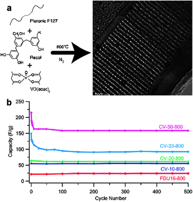 | ||
| Fig. 8 (a) An example of the synthesis of ordered mesoporous carbon composite films containing metal oxide nanoparticles by the soft-templating method. (b) Cycle performance of the carbon–vanadium oxide films. CV-50-800 means carbon–vanadium films prepared by adding 50 wt% VO(acac)2 in the precursor solution and then by pyrolysis at 800 °C; this rule applies to other sample names. FDU16-800 represents pure mesoporous carbon obtained after pyrolysis at 800 °C. The figures are reproduced with permission from ref. 64. | ||
The CASH method (Fig. 7a) using BCPs as structure-directing agents can produce porous carbon–metal oxide hybrids with large pores (diameter >5 nm),65,66 which are desirable to provide easy access of electrolyte molecules to the functional composite in batteries.12 However, some limitations exist, such as low carbon yield and low degree of graphitization of the sp2 hybridized carbon source (e.g. polyisoprene). Therefore, the addition of another carbon source in the assembly precursors is required to increase the carbon yield and the graphitic degree. Lee et al. recently reported a one-pot synthesis of nanostructured, porous and highly crystalline TiO2–carbon composites with large (>5 nm), tunable and uniform pores.65 The PI-b-PEO copolymer was used to direct the formation of TiO2. An additional carbon source, poly(furfuryl alcohol), was added to the precursor solution, which, along with the TiO2 precursor, selectively swelled the hydrophilic PEO block. During heat treatment of the as-prepared composites at ca. 700 °C under an inert atmosphere, PEO was calcined off, while the amorphous TiO2 and poly(furfuryl alcohol) were converted into crystalline TiO2 and conducting carbon, respectively. Meanwhile, the PI blocks containing the sp2 hybridized carbon atoms were converted to an amorphous carbon scaffold, giving rise to porosity and a worm-like morphology of the carbon–TiO2 composites (Fig. 9a). The performance of the resulting composites as anode materials in lithium batteries was investigated. The electrodes were cycled with a specific current of 0.2 C in the voltage range of 1.0–3.0 V (vs. Li/Li+). It was found that the electronic conductivity of the carbon–TiO2 composites (9.4 × 10⁻³ S cm−1) was much higher than that of pure mesoporous TiO2 (8.7 × 10⁻⁷ S cm−1). In addition, the composites exhibited high capacities (0.65 Li/Ti for insertion and 0.55 Li/Ti for desertion), which exceeded those of the pure mesoporous TiO2 (0.6 Li/Ti for insertion and 0.3 Li/Ti for desertion). Also, the composites showed stable cycle performance up to 50 cycles and the specific charge capacity at 30 C was maintained at 38 mA h g−1 (Fig. 9b), which is much higher than that of the pure mesoporous TiO2.65 Such excellent electrochemical performance can be attributed to the stable conductive pathways provided by the carbon as well as the nano-size pores within the TiO2 grains, which have good structural stability upon lithium insertion/desertion processes.
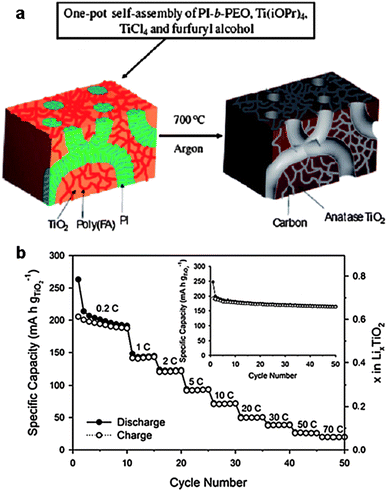 | ||
| Fig. 9 (a) Schematic representation of the “one-pot” synthesis of mesoporous crystalline TiO2–carbon composites with large and uniform pores via carbonization of mesostructured PI-b-PEO/amorphous TiO2/poly(furfuryl alcohol). (b) Rate performance for the TiO2–carbon electrode cycled at different rates. Inset: cycle performance of the TiO2–carbon electrode at 0.2 C in the voltage range of 1.0–3.0 V.65 The figures are reproduced with permission from ref. 12 and 65. | ||
An alternative protocol to overcome the limitations of low carbon yield and low degree of graphitization of the sp2 hybridized carbon is to use BCPs with a high carbon-yield hydrophobic block, such as polyacrylonitrile (PAN) which is an excellent precursor for the graphitic carbon. Stefik et al. employed a diblock copolymer, PAN-b-PEO, as the structure-directing agent for the one-pot synthesis of porous carbon–crystalline TiO2 nanocomposites.67 After the co-assembly of the copolymer with TiO2 NPs, the resultant hybrids were first thermally treated at 250 °C in air to stabilize the PAN and then treated at 700 °C under argon to obtain carbon–crystalline TiO2 composites. During this process, the PAN blocks were transformed into graphitic carbon and templated the composites with a worm-like porous structure. Later, they demonstrated that this route was also useful for ABCBA-type block terpolymers, such as PAN-b-PEO-b-PPO-b-PEO-b-PAN.68 With this polymer, it is possible to simultaneously achieve independent control over three separate components: the carbon amount determined by the length of the PAN segment; the pore size by the molecular weight of the PPO part; and the thickness of the metal oxide domains controlled by the PEO molar mass and the amount of inorganic precursors. The resulting composites represent a new class of materials referred to as block sequence directed materials (BSDMs), which open possibilities for the exploration of novel multifunctional materials in energy conversion and storage devices.68
3. Graphene as structure-directing agent
BCPs exhibit remarkable advantages in the fabrication of metal oxide-containing materials with controlled structures and even hierarchical architecture, while graphene, recently recognized as a 2D polymer, provides a unique platform for the controlled synthesis of various graphene–metal oxide hybrids for electrochemical energy storage. In this respect, graphene oxide (GO) is widely used due to its good dispersability and processibility in solution as well as the associated abundant oxygen-containing groups on the graphene surface which offer opportunities for the further functionalization. In hybrids, GO is generally transformed to reduced graphene oxide (RGO), which can not only protect against the aggregation and volume change of metal oxide NPs during electrochemical reactions, but also provide a fast electron-transport pathway in the overall electrode.2,4,18–21 Nevertheless, the undefined structure of graphene–metal oxide hybrids and intrinsic incompatibility between graphene and metal oxides or their precursors usually result in the reduction of the electrochemical performance. Therefore, the controlled synthesis of graphene–metal oxide hybrids with well-defined structures is of great interest. A tremendous number of papers have been published on this topic.69 Considering the space limitations of the feature article, in this section we introduce the controlled preparation of graphene–metal oxide hybrids with 2D and 3D structures, using the selective examples primarily from our group.3.1. Two-dimensional graphene–metal oxide nanohybrids
Two dimensional nanostructures are of great interest in energy storage devices, especially LIBs, owing to its short-ended paths for fast lithium ion diffusion and large exposed surface offering more lithium-insertion channels.70 So far a wide range of 2D graphene–metal oxide nanohybrids have been developed as electrode materials in LIBs or supercapacitors. The metal oxides investigated include SnO2,71–75 Fe3O4,76–79 Co3O4,80–82 TiO2,75,83–85 CuO,86,87 Mn3O4,88,89 MnO2,90,91 and some mixed metal oxides,92,93 among others. The ex situ and in situ techniques are typically employed for the fabrication of these 2D nanohybrids.94 The ex situ strategy involves the prior synthesis of metal oxide nanostructures in the desired dimensions and morphology, then coupled to the surface of functionalized graphene structures. The in situ growth technique involves the attachment of metal oxide precursors (such as metal salts) in the presence of pristine or functionalized graphene nanosheets, followed by the growth and formation of metal oxide nanostructures on the surface of graphene nanosheets. Comparatively, the in situ growth technique is more widely used. This route avoids extra protecting surfactants or linker molecules which cause tedious experimental procedures and also influence the functions of the resultant hybrids.By the in situ growth means, the morphology of metal oxide NPs on graphene nanosheets can be controlled by tuning the surface chemistry of graphene, leading to the controllable electrochemical performance of the resulting graphene–metal oxide nanohybrids.95 For example, we recently reported the fabrication of porous iron oxide ribbon–graphene nanocomposites by the controlled growth of iron glycolate on the surface of poly(N-vinyl-2-pyrrolidone) (PVP)-functionalized graphene, followed by thermal annealing at 250–400 °C in air (Fig. 10a and b).96 The resulting iron oxide ribbons possess a large aspect ratio and porous structure, providing numerous open channels which facilitate the access of electrolyte and thereby rapid diffusion of lithium ions from electrolyte to electrode. The ribbon morphology also accommodates the volume variation of the iron oxides upon lithium insertion. As a result, the nanohybrids exhibited a reversible capacity of 1050 mA h g−1 in the first 10 cycles and over 1000 mA h g−1 after 130 cycles (Fig. 10c). By comparison, the capacity of pure ion oxide ribbons obtained under similar testing conditions dropped to ∼260 mA h g−1 after 30 cycles. The high electrochemical performance of the iron oxide ribbon–graphene nanohybrids is superior to some of the previously reported iron oxide-based nanomaterials, including iron oxide nanotubes and iron oxide/carbon composites obtained under similar testing conditions.96 In another study related to iron oxides, we demonstrated the growth of FeOOH nanorods uniformly on the GO surface via the hydrolysis of Fe3+ cations which are bound with the oxygen-containing groups via electrostatic interactions.97 Upon electrochemical cycles in the potential range of 0.1–1.3 V (vs. SCE), the original FeOOH nanorods transformed into Fe3O4 NPs, leading to the formation of 2D graphene–Fe3O4 nanocomposites. The composites showed a high energy density (85 W h kg−1) with the average working potential up to −0.8 V (vs. SCE) and good stability maintaining 95% of its initial specific capacitance (∼320 F g−1) at a current density of 2 A g−1 after 1000 cycles. In contrast, the capacitance of pure Fe3O4 reduced rapidly with less than 50% of its initial value (∼170 F g−1) remained.97
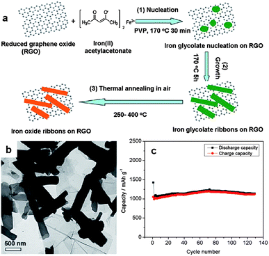 | ||
| Fig. 10 (a) Fabrication of iron oxide ribbons on graphene nanosheets. (b) A TEM image of the graphene–iron oxide nanohybrids. (c) Cycle performance of the nanocomposites at a current density of 74 mA g−1 in the voltage range of 0.01–3.0 V. The figures are reproduced with permission from ref. 96. | ||
For metal oxide NPs on graphene nanosheets, often the electrical conductivity of the hybrids is still not satisfactory, and the aggregation of the NPs is difficult to be suppressed, especially when the NPs are loaded in high density. The aggregation of the NPs seriously influences the structural stability and consequently the electrochemical performance of the resulting nanohybrids. In order to overcome these problems, additional carbon layers can be introduced on graphene–metal oxide hybrid nanosheets to confine the metal oxide NPs on the graphene substrate.74,98,99 Recently, our group developed a facile stepwise approach towards 2D carbon-coated graphene–metal oxide (G@MO@C) nanosheets.74 With phenol-formaldehyde (PF) resol as the carbon source, 2D G@MO@C nanosheets were prepared by the pyrolysis of G@MO@PF at 500 °C in N2 (Fig. 11a). By this means, monodisperse 2D G@SnO2@C and G@Fe3O4@C nanosheets were prepared, indicating the general applicability of the synthetic protocol. As electrode materials, the resulting nanocomposites showed remarkable electrochemical performance for lithium storage. For instance, G@SnO2@C nanosheets exhibited a reversible capacity of up to 800 mA h g−1 at a current density of 200 mA g−1 in a voltage window of 0.01–3.0 V, which was maintained without apparent loss after 100 cycles. Moreover, a high rate capacity up to 260 mA h g−1 at 5000 mA g−1 was achieved for the G@SnO2@C nanosheets, which is much higher than that of the G@SnO2 nanosheets (Fig. 11b–d). The superior electrochemical performance is attributed to the coated carbon layers, which not only enhance the electrical conductivity of the 2D nanocomposite, but also improve the structural stability of the electrode by suppressing the aggregation of SnO2 NPs and accommodate their volume expansion during the cycling processes.74
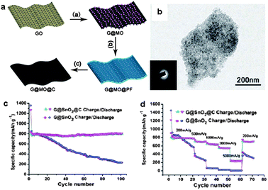 | ||
| Fig. 11 (a) Schematic illustration of the synthesis of 2D G@MO@C hybrid nanosheets. (b) A TEM image of G@SnO2@C nanosheets. (c) Reversible charge/discharge capacities against cycle number for G@SnO2 and G@SnO2@C at a current density of 200 mA g−1 in a voltage window of 0.01–3.0 V. (d) Rate performance of G@SnO2 and G@SnO2@C electrodes. The figures are reproduced with permission from ref. 74. | ||
In addition to NPs, 2D metal oxide porous sheets can also be introduced on the surface of graphene by the in situ technique, taking advantage of the 2D nature of graphene. The resulting hybrid nanosheets inherit the intrinsic features of graphene, such as high surface area, large aspect ratios, and excellent electrical conductivity.100 We recently developed an approach for the fabrication of graphene-based mesoporous silica (G–silica) nanosheets. The synthesis employed cetyltrimethylammonium bromide (CTAB)-modified GO sheets as a template and tetraethylorthosilicate (TEOS) as the silica precursor. After the sol–gel process of the TEOS on the graphene and the pyrolysis of the GO–silica nanosheets at 800 °C in argon, G–silica nanosheets were obtained, in which graphene sheets are sandwiched by two mesoporous silica layers (Fig. 12a).100 Building on this method, mesoporous G–TiO2 composite nanosheets were also fabricated by treating the preformed G–silica nanosheets with (NH4)2TiF6, followed by pyrolysis at 500 °C in argon and etching to remove the silica layers (Fig. 12a and b).101 The resulting G–TiO2 nanosheets have an average thickness of ∼50 nm and a high surface area of ∼200 m2 g−1. The numerous open channels in the G–TiO2 nanosheets allow for the easy access of electrolyte, facilitating the fast diffusion of lithium ions during the cycling processes. Moreover, the graphene layer within each nanosheet acts as a mini-current collector, accelerating the electron transport in the electrode. As a consequence, the G–TiO2 nanosheets show excellent cycle performance along with high reversible capacities of 162 and 123 mA h g−1 at 1 C and 10 C in a voltage range of 1.0–3.0 V, respectively (Fig. 12c). In contrast, the capacity of TiO2 nanosheets without graphene rapidly decreases to 75 and 36 mA h g−1 under the same testing conditions.101
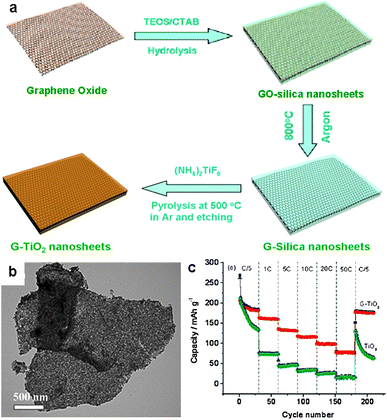 | ||
| Fig. 12 (a) Schematic illustration of the fabrication of graphene-based titania (G–TiO2) composite nanosheets. (b) A TEM image of the nanosheets. (c) Cycle performance of G–TiO2 and TiO2 nanosheets at various current densities in a voltage range of 1.0–3.0 V. The figures are reproduced with permission from ref. 101. | ||
3.2. Three-dimensional graphene–metal oxide hybrids
The self-assembly of 2D graphene sheets as building blocks into 3D architectures may provide resultant graphene-based composites with strong mechanical strength, and fast ion and electron transport due to the combination of the 3D interconnected framework and the intriguing properties of graphene. In this regard, 3D graphene–metal oxide hybrids are desired materials for monolithic composite electrodes, in which the graphene network provides a 3D charge transport pathway and simultaneously suppresses the aggregation of metal oxide NPs and accommodates their volume variation.80,102–113 Graphene–metal oxide aerogels are one of such materials and have attracted considerable attention.105,108–113A general approach to prepare 3D graphene–metal oxide aerogels involves the formation of graphene–metal oxide hydrogels in water, followed by the removal of water by, e.g. freeze drying. The graphene–metal oxide hydrogels can be produced via the introduction of inorganic metal salts into a GO aqueous dispersion. The electrostatic interaction between GO and inorganic metal ions results in the decoration of the metal ions on the GO as well as the formation of a 3D hybrid network. Hydrothermal treatment of the mixture induces the reduction of the GO to RGO and the inorganic metal salts to metal oxide NPs; simultaneously the self-assembly of the RGO attached with metal oxide NPs, driven by the hydrophobic interaction, leads to the formation of graphene–metal oxide hydrogels.108–110 As an example, we recently reported the fabrication of 3D Fe2O3–graphene aerogels (Fe2O3/GAs) by a one-pot hydrothermal process (Fig. 13a).110 First, Fe3+ cations from FeCl3 favourably bind with the oxygen-containing groups on GO sheets via the electrostatic interaction, which also causes the formation of a 3D GO–Fe3+ hybrid network. Second, the hydrolysis of Fe3+ at 80 °C leads to the formation of FeO(OH) nanorods. Third, the GO is transformed into RGO and the FeO(OH) nanorods are transformed into Fe2O3 NPs by hydrothermal treatment; the simultaneous self-assembly of the RGO supported Fe2O3 NPs yields 3D Fe2O3–graphene hydrogels. Finally, Fe2O3/GAs are obtained after the freeze drying of the hydrogels. The resultant 3D Fe2O3/GAs possess interconnected macroporous architecture with a uniform distribution of Fe2O3 NPs in the 3D monolithic networks (Fig. 13b). Such structure provides highly conductive networks with enhanced surface areas (77 m2 g−1) and short diffusion path lengths for lithium ion transport. When applied as the anode material for lithium storage, the Fe2O3/GAs exhibit outstanding reversible capacity and excellent rate performance (995 mA h g−1 after 50 cycles at a charge/discharge rate of 100 mA g−1 in a voltage window of 0.01–3.0 V and reversible discharging capacity 372 mA h g−1 at 5000 mA g−1, see Fig. 13c and d).110 In contrast, physically mixed Fe2O3/GNs (Fe2O3 particles supported on graphene nanosheets) showed a much lower first-cycle discharge capacity, and the capacity dropped quickly to 263 mA h g−1 after 50 cycles (Fig. 13c) due to the aggregation of the Fe2O3 particles demonstrated by SEM observation.
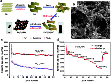 | ||
| Fig. 13 (a) Schematic illustration of the synthesis route towards 3D Fe2O3–graphene aerogels (Fe2O3/GAs). (b) Typical SEM images of the Fe2O3/GAs revealing the 3D macroporous structure and uniform distribution of Fe2O3 NPs. (c) Cycling performance of the Fe2O3/GAs and 2D graphene–Fe2O3 sheets (Fe2O3/GNs) at a current density of 100 mA g−1 in a voltage window of 0.01–3.0 V. (d) Rate capacity of the Fe2O3/GAs with increasing current density in a voltage window of 0.01–3.0 V. The figures are reproduced with permission from ref. 110. | ||
Graphene–metal oxide hydrogels can also be prepared through the self-assembly of graphene and preformed metal oxide NPs in water. Yan and co-workers reduced GO to RGO with NaHSO3 in the presence of Fe3O4 NPs; the self-assembly of the RGO and the Fe3O4 NPs generated graphene–Fe3O4 hydrogel which gave rise to aerogel after freezing drying.105 Fe3O4 NPs were found to distribute homogeneously on both sides of graphene nanosheets in the 3D network, which efficiently prevented the graphene nanosheets from stacking, leading to full usage of the both sides of graphene nanosheets for lithium insertion/desertion during the charging/discharging process. Also, the graphene network provided high electrical conductivity. As a result, the graphene–Fe3O4 aerogel showed a high capacity of ∼990 mA h g−1 when the current density was below 800 mA g−1 in a voltage range of 0.79–1.5 V; the capacity value remained at ∼730 mA h g−1 even at a current density of 1600 mA g−1. Moreover, a capacity of ∼1100 mA h g−1 was retained after 50 charge–discharge cycles at various current densities, indicating good cycling stability.105
In 3D graphene–metal oxide aerogels, the aggregation and volume variations of the metal oxide NPs are hard to avoid due to the dissociation of graphene from the NPs during electrochemical cycling processes. To solve this problem, our group recently developed a method which utilizes graphene-encapsulated Fe3O4 nanospheres (Fe3O4 NSs) as a precursor to co-assemble with graphene via a hydrothermal procedure (Fig. 14).111 First, graphene oxide (GO)-encapsulated Fe3O4 NSs (Fe3O4@GO) were prepared using our protocol for the co-self-assembly of positively charged aminopropyltrimethoxysilane (APS)-modified Fe3O4 NSs and negatively charged GO sheets.114 Second, hydrothermal treatment of an aqueous dispersion of GO and the Fe3O4@GO resulted in the reduction of GO to graphene; simultaneously the co-assembly of the graphene and Fe3O4@GS (Fe3O4 NSs wrapped with graphene sheets) produced 3D graphene–Fe3O4 hydrogel with Fe3O4@GS embedded. Finally, 3D graphene foam cross-linked with Fe3O4@GS (Fe3O4@GS/GF) was obtained after freeze drying and heat treatment of the hydrogel at 500 °C in argon (Fig. 14a–c).111 Such unique hierarchical graphene–Fe3O4 architecture provides double protection against the volume changes of Fe3O4 NSs during electrochemical processes, by the synergistic integration of the graphene shells and the 3D graphene networks. In addition, the Fe3O4@GS/GF hybrids showed a porous structure with the coexistence of macro- and meso-pores, leading to a much higher surface area (∼115 m2 g−1) than those of Fe3O4@GS (∼8 m2 g−1) and Fe3O4 NSs (∼2 m2 g−1). The hierarchical porous structure is favorable for electrolyte accessibility and rapid lithium-ion diffusion. Therefore, the Fe3O4@GS/GF exhibited superior cycling performance (1059 mA h g−1 over 150 cycles at 93 mA g−1 in a potential window of 0.01–3.0 V) and excellent rate capability (363 mA h g−1 at 4800 mA g−1) when used as an anode material for lithium storage (Fig. 14d and e).111 The electrochemical performance is much better than that of Fe3O4@GS or Fe3O4 NSs (Fig. 14d and e).
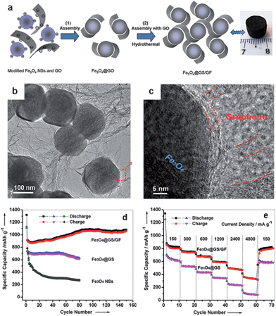 | ||
| Fig. 14 (a) Fabrication process and photograph of Fe3O4@GS/GF: (1) self-assembly of positively charged Fe3O4 NSs and negatively charged GO via the electrostatic interaction; (2) hydrothermal self-assembly of Fe3O4@GO and GO. (b and c) Representative TEM and HRTEM images of Fe3O4@GS/GF; the red curves in (c) indicate that the Fe3O4 NS is wrapped by graphene shells and interconnected by graphene networks. (d) Cycling performance of Fe3O4@GS/GF, Fe3O4@GS, and Fe3O4 NSs at a current density of 93 mA g−1 in a potential range of 0.01–3.0 V. (e) Cycling performance of Fe3O4@GS/GF and Fe3O4@GS at various current densities. The figures are reproduced with permission from ref. 111. | ||
In addition to the approaches mentioned above, 3D graphene–metal oxide frameworks can also be prepared by the growth of metal oxides in preformed graphene aerogels. This means allows for the controllable fabrication of hierarchical macro- and mesoporous 3D graphene-based structures. Recently, Wu et al. demonstrated this strategy for the synthesis of 3D graphene–Co3O4 and graphene–RuO2 hybrids (Fig. 15).113 First, 3D graphene aerogels with interconnected macropores were attained by hydrothermal self-assembly of GO. Then, mesopores were introduced by the growth of silica networks on the graphene surface. The as-prepared 3D graphene–SiO2 composites exhibited narrow interconnected macroporous networks, mesopore size distribution (2–3.5 nm), and a high surface area of 350 m2 g−1. Finally, graphene–Co3O4 and graphene–RuO2 hybrids were synthesized by infiltration of the as-prepared graphene–SiO2 into a 2-isopropanol solution of cobalt acetylacetonate or ruthenium acetylacetonate, followed by heating at 350 °C in air and NaOH etching of the mesoporous silica. The resulting graphene–metal oxide hybrids showed 3D interconnected macroporous frameworks associated with mesoporous and crystalline structures of metal oxides. Such hierarchical architecture offered the hybrids excellent electrochemical performance as electrode materials for supercapacitors. For example, the graphene–RuO2 hybrids manifested a high specific capacitance of 560 F g−1 and the pseudocapacitive utilization of RuO2 in the hybrids was as high as ∼1090 F g−1, which is comparable to the best reported values.113
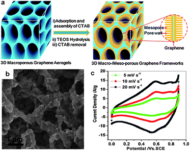 | ||
| Fig. 15 (a) Fabrication of hierarchical macro- and mesoporous graphene–SiO2 hybrids based on preformed graphene aerogels. (b) A representative SEM image of graphene–Co3O4 hybrids. (c) The electrochemical performance of graphene–RuO2 electrodes for supercapacitors, measured at different scan rates of 5, 10, 20 mV s−1 in 1 M H2SO4 electrolyte. The figures are reproduced with permission from ref. 113. | ||
4. Summary and outlook
This feature article describes polymer-directed synthesis of MOCNMs for electrochemical energy storage, using BCPs and graphene as two classical structure-directing agents. BCPs play an important role in the controlled synthesis of porous MOCNMs of tunable morphologies, sizes, and electrochemical properties, by varying the copolymer composition, the volume fraction of the copolymer to metal oxide, the temperature of thermal treatment, etc. The soft-templating and CASH methods are introduced, using typical examples, for the fabrication of porous metal oxide nanostructures and carbon–metal oxide hybrids, respectively. On the other hand, graphene shows extraordinary advantages in the fabrication of unprecedented carbon–metal oxide hybrids for LIBs and supercapacitors, owing to its unique 2D structure, high surface area, mechanical flexibility, high chemical stability, and excellent electrical and thermal conductivity. This article selectively introduces the preparation of graphene–metal oxide hybrids with 2D and 3D architecture based on different synthetic strategies. In these composites, synergistic interactions between graphene and metal oxides fully exert the functions of the two individual components and consequently offer the composites excellent electrochemical performance in LIBs or supercapacitors.The current development of high performance energy storage devices is advancing the design and preparation of MOCNMs. There also remain a number of challenges. For example, (1) the interfacial interactions between metal oxide NPs and BCPs or graphene need to be better understood and further improved. This is crucial for the preparation of well-defined self-assembled structures and their applications that involve charge transfer processes, as poor interfacial interactions between NPs and graphene or BCPs influence the regularity of the self-assembled structures and destroy the synergetic effects between the two components, thereby diminishing the electrochemical performance of the hybrids. (2) Rational design and control of the structure and composition of MOCNMs need deeper understanding of the structure–property relationship. This requires systematic studies from both theoretical and experimental perspectives. (3) New and complex metal oxide-containing nanostructures that provide high surface area for intimate contact with the electrolyte and short diffusion paths for ion and electron transport are in demand. For example, bicontinuous hierarchical nanostructures containing both mesopores and macropores are expected to be synthesized using triblock terpolymers as templates, which possess a significantly larger phase window of bicontinuous structures compared with diblock copolymers. The complexity of the so far obtained metal oxide-containing nanostructures is much lower compared with that of the self-assembled structures in nature. As the polymer synthetic technique advances, a wealth of MOCNMs with more complex architecture are going to emerge with sequence control of more than three monomers in multiblock copolymers. (4) The industrial applications of MOCNMs require large-scale, low-cost and simple production methods; thus a comprehensive improvement in methodology of production is a must. With the challenges overcome and interdisciplinary collaboration enhanced, the commercialization of MOCNMs prepared with BCPs and graphene as structure-directing agents is a distinct possibility in the near future.
Acknowledgements
The authors thank the financial support from the 973 Program of China (2012CB933404), the Natural Science Foundation of China (21320102006 and 21304057), the Natural Science Foundation of Shanghai City (13ZR1421200), the Shanghai Pujiang Program (11J1405400), and ERC Grant on 2DMATER.References
- Y. Guo, J. Hu and L. Wan, Adv. Mater., 2008, 20, 2878–2887 CrossRef CAS.
- Y. Sun, Q. Wu and G. Shi, Energy Environ. Sci., 2011, 4, 1113–1132 CAS.
- B. Scrosati, J. Hassoun and Y.-K. Sun, Energy Environ. Sci., 2011, 4, 3287–3295 CAS.
- S. Yang, R. E. Bachman, X. Feng and K. Müllen, Acc. Chem. Res., 2013, 46, 116–128 CrossRef CAS PubMed.
- J. Lee, J. Kim and T. Hyeon, Adv. Mater., 2006, 18, 2073–2094 CrossRef CAS.
- Y. Zhai, Y. Dou, D. Zhao, P. F. Fulvio, R. T. Mayes and S. Dai, Adv. Mater., 2011, 23, 4828–4850 CrossRef CAS PubMed.
- H. Wu, J. Chen, H. H. Hng and X. Lou, Nanoscale, 2012, 4, 2526–2542 RSC.
- W. Shi, X. Rui, J. Zhu and Q. Yan, J. Phys. Chem. C, 2012, 116, 26685–26693 CAS.
- G. J. A. A. Soler-Illia, C. Sanchez, B. Lebeau and J. Patar, Chem. Rev., 2002, 102, 4093–4138 CrossRef PubMed.
- D. M. Antonelli and J. Y. Ying, Angew. Chem., Int. Ed., 1995, 34, 2014–2017 CrossRef CAS.
- G. J. de A. A. Soler-Illia, E. L. Crepaldi, D. Grosso and C. Sanchez, Curr. Opin. Colloid Interface Sci., 2003, 8, 109–126 CrossRef CAS.
- M. C. Orilall and U. Wiesner, Chem. Soc. Rev., 2011, 40, 520–535 RSC.
- R. Zhang, A. A. Elzatahry, S. S. Al-Deyab and D. Zhao, Nano Today, 2012, 7, 344–366 CrossRef CAS PubMed.
- M. Llusar and C. Sanchez, Chem. Mater., 2008, 20, 782–820 CrossRef CAS.
- F. Jiao, A. Harrison, J. C. Jumas, A. V. Chadwick, W. Kockelmann and P. G. Bruce, J. Am. Chem. Soc., 2006, 128, 5468–5474 CrossRef CAS PubMed.
- Z. Wang, D. Luan, C. Li, F. Su, S. Madhavi, F. Y. C. Boey and X. Lou, J. Am. Chem. Soc., 2010, 132, 16271–16277 CrossRef CAS PubMed.
- B. C. Satishkumar, A. Govindaraj, M. Nath and C. N. R. Rao, J. Mater. Chem., 2000, 10, 2115–2119 RSC.
- Y. Zhu, S. Murali, W. Cai, X. Li, J. W. Suk, J. R. Potts and R. S. Ruoff, Adv. Mater., 2010, 22, 3906–3924 CrossRef CAS PubMed.
- D. Wu, F. Zhang, H. Liang and X. Feng, Chem. Soc. Rev., 2012, 41, 6160–6177 RSC; D. Wu, F. Zhang, P. Liu and X. Feng, Chem.–Eur. J., 2011, 17, 10804–10812 CrossRef CAS PubMed; S. Han, D. Wu, S. Li, F. Zhang and X. Feng, Small, 2013, 9, 1173–1187 CrossRef PubMed.
- L. Dai, Acc. Chem. Res., 2013, 46, 31–42 CrossRef CAS PubMed.
- H. Wang and H. Dai, Chem. Soc. Rev., 2013, 42, 3088–3113 RSC.
- Y. Mai and A. Eisenberg, Chem. Soc. Rev., 2012, 41, 5969–5985 RSC.
- F. S. Bates and G. H. Fredrickson, Phys. Today, 1999, 52, 32–38 CrossRef CAS.
- C. G. Göltner, S. Henke, M. C. Weissenberger and M. Antonietti, Angew. Chem., Int. Ed., 1998, 37, 613–616 CrossRef.
- H. Shen and A. Eisenberg, J. Phys. Chem. B, 1999, 103, 9473–9487 CrossRef CAS.
- S. Jain and F. S. Bates, Science, 2003, 300, 460–464 CrossRef CAS PubMed.
- B. C. Garcia, M. Kamperman, R. Ulrich, A. Jain, S. M. Gruner and U. Wiesner, Chem. Mater., 2009, 21, 5397–5405 CrossRef CAS.
- R. Ivanova, P. Alexandridis and B. Lindmann, Colloids Surf., A, 2001, 183–185, 41–53 CrossRef CAS.
- S. Granick, S. K. Kumar, E. J. Amis, M. Antonietti, A. C. Balazs, A. K. Chakraborty, G. S. Grest, C. J. Hawker, P. Janmey, E. J. Kramer, R. Nuzzo, T. P. Russell and C. R. Safinya, J. Polym. Sci., Part B: Polym. Phys., 2003, 41, 2755–2793 CrossRef CAS; I. W. Hamley, Prog. Polym. Sci., 2009, 34, 1161–1210 CrossRef PubMed.
- S. A. Bagshaw, E. Prouzet and T. J. Pinnavaia, Science, 1995, 269, 1242–1244 CrossRef PubMed.
- M. Templin, A. Franck, A. Du Chesne, H. Leist, Y. Zhang, R. Ulrich, V. Schadler and U. Wiesner, Science, 1997, 278, 1795–1798 CrossRef CAS.
- D. Zhao, J. Feng, Q. Huo, N. Melosh, G. H. Frederickson, B. F. Chmelka and G. D. Stucky, Science, 1998, 279, 548–552 CrossRef CAS.
- P. Yang, D. Zhao, D. I. Margolese, B. F. Chmelka and G. D. Stucky, Nature, 1998, 396, 152–155 CrossRef CAS PubMed.
- P. Yang, D. Zhao, D. I. Margolese, B. F. Chmelka and G. D. Stucky, Chem. Mater., 1999, 11, 2813–2826 CrossRef CAS.
- P. C. A. Alberius, K. L. Frindell, R. C. Hayward, E. J. Kramer, G. D. Stucky and B. F. Chmelka, Chem. Mater., 2002, 14, 3284–3294 CrossRef CAS.
- Q. Wu and S. E. Rankin, J. Phys. Chem. C, 2011, 115, 11925–11933 CAS.
- C. J. Brinker, Y. Lu, A. Sellinger and H. Fan, Adv. Mater., 1999, 11, 579–585 CrossRef CAS.
- X. Jiang and C. J. Brinker, Chem. Commun., 2010, 46, 6123–6125 RSC.
- C. Sanchez, C. Boissière, D. Grosso, C. Laberty and L. Nicole, Chem. Mater., 2008, 20, 682–737 CrossRef CAS.
- I. E. Rauda, V. Augustyn, B. Dunn and S. Tolbert, Acc. Chem. Res., 2013, 46, 1113–1124 CrossRef CAS PubMed.
- B. Tian, H. Yang, X. Liu, S. Xie, C. Yu, J. Fan, B. Tu and D. Zhao, Chem. Commun., 2002, 1824–1825 RSC.
- B. Tian, X. Liu, B. Tu, C. Yu, J. Fan, L. Wang, S. Xie, G. D. Stucky and D. Zhao, Nat. Mater., 2003, 2, 159–163 CrossRef CAS PubMed.
- E. L. Crepaldi, G. Soler-Illia, D. Grosso, F. Cagnol, F. Ribot and C. Sanchez, J. Am. Chem. Soc., 2003, 125, 9770–9786 CrossRef CAS PubMed.
- S. Haseloh, S. Y. Choi, M. Mamak, N. Coombs, S. Petrov, N. Chopra and G. A. Ozin, Chem. Commun., 2004, 1460–1461 RSC.
- B. Smarsly, D. Grosso, T. Brezesinski, N. Pinna, C. Boissière, M. Antonietti and C. Sanchez, Chem. Mater., 2004, 16, 2948–2952 CrossRef CAS.
- D. Grosso, C. Boissiere, B. Smarsly, T. Brezesinski, N. Pinna, P. A. Albouy, H. Amenitsch, M. Antonietti and C. Sanchez, Nat. Mater., 2004, 3, 787–792 CrossRef CAS PubMed.
- T. Brezesinski, J. Wang, S. H. Tolbert and B. Dunn, Nat. Mater., 2010, 9, 146–151 CrossRef CAS PubMed.
- T. Brezesinski, J. Wang, J. Polleux, B. Dunn and S. H. Tolbert, J. Am. Chem. Soc., 2009, 131, 1802–1809 CrossRef CAS PubMed.
- M. Groenewolt, T. Brezesinski, H. Schlaad, M. Antonietti, P. W. Groh and B. Ivan, Adv. Mater., 2005, 17, 1158–1162 CrossRef CAS.
- J. Lee, M. C. Orilall, S. C. Warren, M. Kamperman, F. J. Disalvo and U. Wiesner, Nat. Mater., 2008, 7, 222–228 CrossRef CAS PubMed.
- Y. Cheng and J. S. Gutmann, J. Am. Chem. Soc., 2006, 128, 4658–4674 CrossRef CAS PubMed; Y. Cheng, L. Zhi, W. Steffen and J. S. Gutmann, Chem. Mater., 2008, 20, 6580–6582 CrossRef.
- A. H. Yuwono, Y. Zhang, J. Wang, X. Zhang, H. Fan and W. Ji, Chem. Mater., 2006, 18, 5876–5889 CrossRef CAS.
- J. Ba, J. Polleux, M. Antonietti and M. Niederberger, Adv. Mater., 2005, 17, 2509–2512 CrossRef CAS.
- I. E. Rauda, R. Buonsanti, L. C. Saldarriaga-Lopez, K. Benjauthrit, L. T. Schelhas, M. Stefik, V. Augustyn, J. Ko, B. Dunn, U. Wiesner, D. J. Milliron and S. H. Tolbert, ACS Nano, 2012, 6, 6386–6399 CrossRef CAS PubMed.
- Z. Zhong, Y. Yin, B. Gates and Y. Xia, Adv. Mater., 2000, 12, 206–209 CrossRef CAS.
- R. A. Caruso, A. Susha and F. Caruso, Chem. Mater., 2001, 13, 400–409 CrossRef CAS.
- D. Grosso, G. J. A. A. Soler-Illia, E. Crepaldi and C. Sanchez, Adv. Funct. Mater., 2003, 13, 37–42 CrossRef CAS.
- A. Khanal, Y. Inoue, M. Yada and K. Nakashima, J. Am. Chem. Soc., 2007, 129, 1534–1535 CrossRef CAS PubMed.
- D. Liu and K. Nakashima, Inorg. Chem., 2009, 48, 3898–3900 CrossRef CAS PubMed.
- U. Ciesla, S. Schacht, G. D. Stucky, K. K. Unger and F. Schueth, Angew. Chem., Int. Ed. Engl., 1996, 35, 541–543 CrossRef CAS.
- R. Zhang, B. Tu and D. Zhao, Chem.–Eur. J., 2010, 16, 9977–9981 CrossRef CAS PubMed.
- R. Liu, Y. Ren, Y. Shi, F. Zhang, L. Zhang, B. Tu and D. Zhao, Chem. Mater., 2008, 20, 1140–1146 CrossRef CAS.
- M. N. Patel, X. Wang, B. Wilson, D. A. Ferrer, S. Dai, K. J. Stevenson and K. P. Johnston, J. Mater. Chem., 2010, 20, 390–398 RSC.
- M. Dai, L. Song, J. T. LaBelle and B. D. Vogt, Chem. Mater., 2011, 23, 2869–2878 CrossRef CAS.
- J. Lee, Y. S. Jung, S. C. Warren, M. Kamerman, S. M. Oh, F. J. DiSalvo and U. Wiesner, Macromol. Chem. Phys., 2011, 212, 383–390 CAS.
- E. Kang, Y. S. Jung, G.-H. Kim, J. Chun, U. Wiesner, A. C. Dillon, J. K. Kim and J. Lee, Adv. Funct. Mater., 2011, 21, 4349–4357 CrossRef CAS.
- M. Stefik, J. Lee and U. Wiesner, Chem. Commun., 2009, 2532–2534 RSC.
- M. Stefik, H. Sai, K. Sauer, S. M. Gruner, F. J. DiSalvo and U. Wiesner, Macromolecules, 2009, 42, 6682–6687 CrossRef CAS.
- Examples include review articles in ref. 2, 4, 18–21, and the publications cited in these reviews.
- J. Liu and X. Liu, Adv. Mater., 2012, 24, 4097–4111 CrossRef CAS PubMed.
- S. Ding, D. Luan, F. Y. C. Boey, J. Chen and X. Lou, Chem. Commun., 2011, 47, 7155–7157 RSC.
- C. Xu, J. Sun and L. Gao, Nanoscale, 2012, 4, 5425–5430 RSC.
- X. Wang, X. Cao, L. Bourgeois, H. Guan, S. Chen, Y. Zhong, D. Tang, H. Li, T. Zhai, L. Li, Y. Bando and D. Golberg, Adv. Funct. Mater., 2012, 22, 2682–2690 CrossRef CAS.
- Y. Su, S. Li, D. Wu, F. Zhang, H. Liang, P. Gao, C. Cheng and X. Feng, ACS Nano, 2012, 6, 8349–8356 CrossRef CAS PubMed.
- Y. Tang, D. Wu, S. Chen, F. Zhang, J. Jia and X. Feng, Energy Environ. Sci., 2013, 6, 2447–2451 CAS.
- M. Zhang, D. Lei, X. Yin, L. Chen, Q. Li, Y. Wang and T. Wang, J. Mater. Chem., 2010, 20, 5538–5543 RSC.
- P. Lian, X. Zhu, H. Xiang, Z. Li, E. Yang and H. Wang, Electrochim. Acta, 2010, 56, 834–840 CrossRef CAS PubMed.
- J. Wang, C. Zhong, D. Wexler, N. H. Idris, Z. Wang, L. Chen and H. Liu, Chem.–Eur. J., 2011, 17, 661–667 CrossRef CAS PubMed.
- W. Chen, S. Li, C. Chen and L. Yan, Adv. Mater., 2011, 23, 5679–5683 CrossRef CAS PubMed.
- Z. Wu, W. Ren, L. Wen, L. Gao, J. Zhao, Z. Chen, G. Zhou, F. Li and H. Cheng, ACS Nano, 2010, 4, 3187–3194 CrossRef CAS PubMed.
- S. Yang, G. Cui, S. Pang, Q. Cao, U. Kolb, X. Feng, J. Maier and K. Müllen, ChemSusChem, 2010, 3, 236–239 CrossRef CAS PubMed.
- C. T. Hsieh, J. Lin, Y. Chen and H. Teng, J. Phys. Chem. C, 2012, 116, 15251–15258 CAS.
- D. Wang, D. W. Choi, J. Li, Z. Yang, Z. Nie, R. Kou, D. Hu, C. Wang, L. V. Saraf, J. Zhang, I. A. Aksay and J. Liu, ACS Nano, 2009, 3, 907–914 CrossRef CAS PubMed.
- J. Chen, Z. Wang, X. Dong, P. Chen and X. Lou, Nanoscale, 2011, 3, 2158–2161 RSC.
- X. Zhang, P. S. Kumar, V. Aravindan, H. Liu, J. Sundaramurthy, S. Mhaisalkar, H. M. Duong, S. Ramakrishna and S. Madhavi, J. Phys. Chem. C, 2012, 116, 14780–14788 CAS.
- L. Lu and Y. Wang, J. Mater. Chem., 2011, 21, 17916–17921 RSC.
- Y. Mai, X. Wang, J. Xiang, Y. Qiao, D. Zhang, C. Gu and J. Tu, Electrochim. Acta, 2011, 56, 2306–2311 CrossRef CAS PubMed.
- H. Wang, L. Cui, Y. Yang, H. S. Casalongue, J. T. Robinson, Y. Liang, Y. Cui and H. Dai, J. Am. Chem. Soc., 2010, 132, 13978–13980 CrossRef CAS PubMed.
- H. Kim, D.-H. Seo, H. Kim, I. Park, J. Hong, K.-Y. Park and K. Kang, Chem. Mater., 2012, 24, 720–725 CrossRef CAS.
- S. Chen, J. W. Zhu, X. Wu, Q. Han and X. Wang, ACS Nano, 2010, 4, 2822–2830 CrossRef CAS PubMed.
- Z. Fan, J. Yan, T. Wei, L. Zhi, G. Ning, T. Li and F. Wei, Adv. Funct. Mater., 2011, 21, 2366–2375 CrossRef CAS.
- L. Shen, C. Yuan, H. Luo, X. Zhang, S. Yang and X. Lu, Nanoscale, 2011, 3, 572–574 RSC.
- H. Wang, Z. Hu, Y. Chang, Y. Chen, H. Wu, Z. Zhang and Y. Yang, J. Mater. Chem., 2011, 21, 10504–10511 RSC.
- S. Bai and X. Shen, RSC Adv., 2012, 2, 64–98 RSC.
- H. Wang, J. T. Robinson, G. Diankov and H. Dai, J. Am. Chem. Soc., 2010, 132, 3270–3271 CrossRef CAS PubMed; H. Wang, H. S. Casalongue, Y. Liang and H. Dai, J. Am. Chem. Soc., 2010, 132, 7472–7477 CrossRef PubMed.
- S. Yang, Y. Sun, L. Chen, Y. Hernandez, X. Feng and K. Müllen, Sci. Rep., 2012, 2, 427 Search PubMed.
- Q. Qu, S. Yang and X. Feng, Adv. Mater., 2011, 23, 5574–5580 CrossRef CAS PubMed.
- B. Li, H. Cao, J. Zhang, M. Qu, F. Lian and X. Kong, J. Mater. Chem., 2012, 22, 2851–2854 RSC.
- X. Zhou, Y. Yin, L. Wan and Y. Guo, J. Mater. Chem., 2012, 22, 17456–17459 RSC.
- S. Yang, X. Feng, L. Wang, K. Tang, J. Maier and K. Müllen, Angew. Chem., Int. Ed., 2010, 49, 4795–4799 CrossRef CAS PubMed.
- S. Yang, X. Feng and K. Müllen, Adv. Mater., 2011, 23, 3575–3579 CrossRef CAS PubMed.
- S. M. Paek, E. Yoo and I. Honma, Nano Lett., 2009, 9, 72–75 CrossRef CAS PubMed.
- G. Zhou, D. Wang, F. Li, L. Zhang, N. Li, Z. Wu, L. Wen, G. Lu and H. Cheng, Chem. Mater., 2010, 22, 5306–5313 CrossRef CAS.
- Y. Ding, Y. Jiang, F. Xu, J. Yin, H. Ren, Q. Zhuo, Z. Long and P. Zhang, Electrochem. Commun., 2010, 12, 10–13 CrossRef CAS PubMed.
- W. Chen, S. Li, C. Chen and L. Yan, Adv. Mater., 2011, 23, 5679–5683 CrossRef CAS PubMed.
- C. Li and G. Shi, Nanoscale, 2012, 4, 5549–5563 RSC.
- X. Dong, H. Xu, X. Wang, Y. Huang, M. B. Chan-Park, H. Zhang, L. Wang, W. Huang and P. Chen, ACS Nano, 2012, 6, 3206–3213 CrossRef CAS PubMed.
- H. Cong, X. Ren, P. Wang and S. Yu, ACS Nano, 2012, 6, 26 CrossRef PubMed , 93–2703.
- Z. Wu, S. Yang, Y. Sun, K. Parvez, X. Feng and K. Müllen, J. Am. Chem. Soc., 2012, 134, 9082–9085 CrossRef CAS PubMed.
- L. Xiao, D. Wu, S. Han, Y. Huang, S. Li, M. He, F. Zhang and X. Feng, ACS Appl. Mater. Interfaces, 2013, 5, 3764–3769 CAS.
- W. Wei, S. Yang, H. Zhou, I. Lieberwirth, X. Feng and K. Müllen, Adv. Mater., 2013, 25, 2909–2914 CrossRef CAS PubMed.
- L. Chen, B. Wei, X. Zhang and C. Li, Small, 2013, 9, 2331–2340 CrossRef CAS PubMed.
- Z. Wu, Y. Sun, Y. Tan, S. Yang, X. Feng and K. Müllen, J. Am. Chem. Soc., 2012, 134, 19532–19535 CrossRef CAS PubMed.
- S. Yang, X. Feng, S. Ivanovici and K. Müllen, Angew. Chem., Int. Ed., 2010, 49, 8408–8411 CrossRef CAS PubMed.
| This journal is © The Royal Society of Chemistry 2014 |


