Hydrothermal synthesis of hydroxyapatite coatings with oriented nanorod arrays
Wei
Chen†
a,
Teng
Long†
b,
Ya-Jun
Guo
a,
Zhen-An
Zhu
*b and
Ya-Ping
Guo
*a
aThe Education Ministry Key Lab of Resource Chemistry and Shanghai Key Laboratory of Rare Earth Functional Materials, Shanghai Normal University, Shanghai 200234, P. R. China. E-mail: ypguo@shnu.edu.cn; Fax: +86-21-64321951; Tel: +86-21-64321951
bShanghai Key Laboratory of Orthopedic Implant, Department of Orthopedic Surgery, Shanghai Ninth People's Hospital, Shanghai Jiao Tong University School of Medicine, Shanghai 200011, China. E-mail: zhuzhenan2006@126.com
First published on 28th October 2013
Abstract
Hydroxyapatite coatings (HACs) with oriented nanorod arrays have been fabricated according to the following stages: (i) sol–gel preparation of bioglass coatings (BGCs) on Ti6Al4V substrates; and (ii) transformation of the BGCs to the HACs in a simulated body fluid (SBF) under hydrothermal conditions. After soaking the BGCs in SBF for 12 h under hydrothermal conditions, the elongated HA rods deposit on the surfaces via a dissolution–precipitation reaction. The TEM image and corresponding ED pattern indicate that the HA rods in the HACs are single crystals with a preferential (002) orientation. With increasing the reaction time to 2 days, most of the HA rods are converted to HA particles due to Ostwald ripening. If SBF is replaced by deionized water, the obtained coatings are rod-like HA with the poor crystal orientation. Beside the reaction time and reaction medium, the reaction conditions play an important role in the morphologies of the HACs. Although a HA layer deposits also on the BGCs after soaking in SBF at 37 °C, the HA crystals exhibit plate-like structure. SBF immersion tests and biocompatibility tests by using human bone marrow stromal cells (hBMSCs) as cell models indicate that the HACs with oriented nanorod arrays exhibit great in vitro bioactivity and biocompatibility. The oriented HA rods on the coatings can not only promote the formation of bone-like apatite, but also improve the adhesion, spreading and proliferation of hBMSCs. The excellent in vitro bioactivity and biocompatibility suggest that the HACs with oriented nanorod arrays have great potential for bone implants.
1. Introduction
Hydroxyapatite (HA) coatings or scaffolds possess excellent biocompatibility and osteoconductivity, which make them have great applications for correction of bone defects caused by trauma, disease or genetic disorders.1 Different kinds of synthesis strategies have been developed to control the particle size, morphology, crystallinity and crystal orientation of HA.2 However, the synthesized HA crystals are still different from the minerals of natural bones in chemical composition, crystallinity, and crystallographic texture.Fortunately, research findings on the chemical composition, microstructure and biomineralization mechanism of natural bones provide an important way to design and fabricate ideal bone implants. Natural bone is a complex hierarchical composite, consisting of a mineral phase (HA) and a protein phase (mostly type 1 collagen).3 The biological HA crystals exhibit poor crystallinity due to the incorporation of impurities such as carbonate, sodium and magnesium ions.4 Recently, Gower et al. have proposed that HA crystals in mineralized collagenous tissues such as bone and dentin do not initially nucleate within hole zones, but rather an amorphous calcium phosphate (ACP) serves as a precursor to create a highly loaded mineral/organic composite with HA nanocrystals oriented in [001] direction along the long axis of collagen fibers.4 Therefore, the ideal bone implants not only should have the similar chemical composition and crystallinity to minerals of natural bone, but also possess the desired crystal orientation.
The preferred orientations of HA crystals are believed to affect the biological and biomechanical performances of bone tissue.5 The HA crystals with the surfaces exhibiting a tailored crystallographic texture may enable a new level of control of cellular behavior and enhance mineralized tissue formation.6 Despite these findings, the deposition of oriented arranged HA nanorods on medical metal substrates remains a big challenge.7
Herein, we report, for the first time, the fabrication of HA coatings (HACs) with oriented nanorod arrays according to the following stages: (i) sol–gel preparation of bioglass coatings (BGCs, CaO–SiO2–P2O5) by using tetraethyl orthosilicate (TEOS) as a silicon source, calcium nitrate as a calcium source and triethyl phosphate (TEP) as a phosphorus source; (ii) transformation of the BGCs to the HACs in a simulated body fluid (SBF) under hydrothermal conditions. The main aims of the present work are to fabricate the HACs, and to investigate the formation mechanism and biocompatibility.
2. Experimental
2.1 Preparation of BGCs
Briefly, 2.80 g of calcium nitrate, 12.30 mL of tetraethyl orthosilicate, 0.70 mL of triethyl phosphate, and 58 mL of ethanol were mixed, followed by addition of 2 mL nitric acid solution (1 mol L−1) as catalytic hydrolysis. The mixtures were stirred for 4 h at 40 °C, and then were aged at 50 °C to form the sol. Ti6Al4V substrates were dipped in the above sol, and then were withdrawn in a rate of 1 mm s−1, followed by calcination at 400 °C for 1 h. The dipping and heating cycle was repeated three times. The obtained bioglass coatings are denoted as BGCs.2.2 Preparation of HACs
SBF was prepared by dissolving reagent grade chemicals of NaCl, NaHCO3, KCl, K2HPO4·3H2O, MgCl2·6H2O, CaCl2, Na2SO4, and (CH2OH)3CNH2 into deionized water, and buffering it at pH 7.40 with hydrochloric acid at 37 °C. The BGCs and 10 mL of SBF were sealed in Teflon-lined stainless steel autoclaves, and reacted for 12 h–2 days at 120 °C. Finally, the products (HACs) were washed with deionized water and dried. In order to investigate the effect of reaction mediums on the morphology, the reference HACs were fabricated hydrothermally under the same conditions, except that SBF was replaced by deionized water. In addition, the BGCs were soaked in 10 mL of SBF at 37 °C for 24 h. The specimens were removed from the SBF, washed with deionized water and dried at room temperature. The obtained products were denoted as SHACs.2.3 In vitro bioactivity of HACs
SBF with ion concentrations approximately equal to those of human blood plasma has been used widely for in vitro assessment of the in vitro bioactivity of coatings. The HACs which were converted from the BGCs by hydrothermal reaction for 12 h were soaked in 25 mL of SBF, and kept at 37 °C. After 12 h the specimens were removed from the SBF, washed with deionized water, and dried at 60 °C.2.4 Cell behaviors of HACs
The study was approved by the Ethic Committee of the Ninth People's Hospital of Shanghai Jiao Tong University. Cells were grown in complete Alpha Minimum Essential Medium (α-MEM; GIBCO, Grand Island, NY, USA) supplemented with 10% fetal bovine serum (FBS; Hyclone, Tauranga, New Zealand) and antibiotics (penicillin 100 U mL−1, streptomycin 100 μg mL−1; Hyclone, Logan, UT, USA) in a 37 °C humidified atmosphere with 5% CO2. Cells at a passage from P3 to P4 were used for these experiments.hBMSCs were seeded on the samples at a density of 1 × 10⁴ cells per sample in a 12-well plate. The number of viable cells was measured with cell counting kit-8 (CCK-8, Dojindo, Kumamoto, Japan). At each time point, 100 μL of water-soluble tetrazolium-8 solution was added to each well, and plates were incubated for 2 h at 37 °C. 200 μL solution of each well was added into a new 96-well plate and absorbance was measured at 450 nm by a microplate spectrophotometer (Bio-Rad Laboratories, Hercules, CA).
The cytoskeleton of hBMSCs on the samples was observed by using double fluorescence staining. Briefly, after cultured at a density of 1 × 10⁴ cells per sample for 24 h in a 12-well plate at 37 °C, the samples were gently washed with PBS and maintained in 4% paraformaldehyde for 15 min, followed by immersing in 0.1% Triton X-100 solution for 15 min. TRITC phalloidin was used to stain the actin filaments of cells, and 4′,6-diamidino-2-phenylindole (DAPI) was used to stain the nucleus of cells. The cytoskeleton of hBMSCs was observed under laser scanning confocal microscopy (LSCM, LEICA TCS-SP2).
2.5 Characterization
The microstructures of the samples were investigated by using scanning electron microscopy (SEM, MX2600, CamScan) and transmission electron microscopy (TEM, CM200/FEG, Philips). The crystalline phases of the samples were examined with X-ray powder diffraction (XRD, D/max-II B, Japan) using CuKα radiation. Fourier Transform Infrared spectra (FTIR, VECTOR22, BRUKER) were collected at room temperature by using the KBr pellet technique, working in the range of wavenumbers 4000–400 cm−1 at a resolution of 2 cm−1 (number of scans ∼60).3. Results and discussion
3.1 Morphology of HACs
The BGCs, which resemble the ACP in natural bone, are used as the precursors to hydrothermally transform into the HACs in SBF. Fig. 1a shows that the BGCs fabricated by the sol–gel method possess the smooth surfaces. After soaking the BGCs in SBF for 12 h under hydrothermal conditions, the elongated HA rods precipitate on the surfaces, as shown in Fig. 1b and c. The morphology of the HACs is much different from the BGCs (Fig. 1). The HA rods with the length of ∼1 μm and the diameter of 40–80 nm are perpendicularly oriented to the surface, and appear to be compacted in uniform coating. The EDS spectrum in Fig. 1d reveals that the chemical elements of the HACs include Ca, P, O, C, Mg, Na, and Si. The Ca, P, O and C elements are mainly derived from the carbonated HA and bioglass, the Na and Mg elements are due to the substitution of the Ca2+ ions in HA crystal lattice by the Na+ and Mg2+ ions, and the Si element is derived from the bioglass. The Mg element plays an important role in bone metabolism and bone regeneration, and Si element can enhance the in vitro and in vivo bone formation ability.8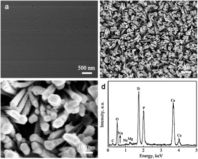 | ||
| Fig. 1 (a) SEM image of BGCs; (b and c) SEM images and (d) EDS spectrum of HACs converted from BGCs after hydrothermal reaction for 12 h in SBF. | ||
Interestingly, the HA rods in the HACs are single crystals with a preferential (002) orientation, as confirmed by the corresponding ED pattern (Fig. 2c). Under the high-resolution TEM image, the lattice spacing is ∼0.35 nm, which is corresponding to the interplanar spacing of (002) planes for hexagonal HA (Fig. 2b). This result confirms that the nanorods grow along the c-axis direction of HA, too. The same orientation is also observed in bone mineralization, as HA nanocrystals have their c-axis parallel to the collagen fibers.4
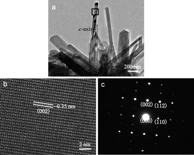 | ||
| Fig. 2 (a) TEM images of the powders scraped from HACs; (b) high-resolution TEM image and (c) ED pattern acquired in the region marked with a square in (a). | ||
3.2 Phase structure of HACs
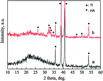
The phases of the BGCs before and after hydrothermal reaction for 12 h in SBF are characterized by XRD patterns, as shown in Fig. 3. For the BGCs, the broad peak at about 2θ = 23° is due to the typical structure of the amorphous bioglass in the coatings. After soaking the BGCs in SBF for 12 h under hydrothermal conditions, the peak due to the amorphous material becomes weak, while the characteristic peaks due to HA are detected. The presence of the amorphous diffraction peak indicates that part of the bioglass is remained in the HACs after hydrothermal reaction for 12 h. The broad characteristic peaks demonstrate that the HA crystals possess poor crystallinity, which is attributed to the incorporation of impurities such as carbonate, sodium and magnesium ions (Fig. 1d). Generally, the HA with poor crystallinity have the better bioactivity, biocompatibility and biodegradability as compared with the stoichiometric HA.The FTIR spectra also confirm the transformation of the BGCs to the HACs in SBF. In the FTIR spectrum of BGCs (Fig. 4a), the absorption bands at 1099, 809, and 464 cm−1 are ascribed to the bending and stretching vibrations of Si–O–Si bonds. The vibrational bands at ∼563 cm−1 is corresponding to the bending vibrations of the phosphate (PO43−) groups.9 After soaking the BGCs in SBF for 12 h under hydrothermal conditions, the absorption peak strength of the crystalline HA are observed in Fig. 4. The absorption band at 1030 cm−1 is ascribed to the stretching vibration (v3) of the phosphate group, and the absorption bands at 564 and 603 cm−1 are ascribed to the bending vibration (v4) of the phosphate group in the crystalline HA phase. The characteristic band of B-type CO32− substitution at 1420 cm−1 (v3) is detected, too.9 The CO32− ions in the HA crystal lattices are mainly originated from the SBF during the formation of HACs. The results of both the XRD patterns and FTIR spectra demonstrate that the BGCs are converted to the HACs after hydrothermal reaction for 12 h in SBF.
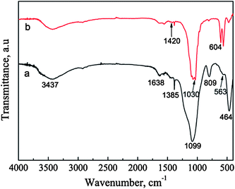 | ||
| Fig. 4 FTIR spectra of BGCs (a) before and (b) after soaking in SBF for 12 h under hydrothermal conditions. | ||
3.3 Formation mechanism of HACs
It is well known that during the biomineralization of the bone minerals, ACP serves as a precursor to create a highly loaded mineral/organic composite with HA nanocrystals oriented in [001] direction along the long axis of collagen fibers.4 In this work, the BGCs and SBF serves as the ACP and body fluid in natural bones, respectively. Under hydrothermal conditions, the BGCs as the precursor are converted to the HACs via the biomineralization mechanism. After soaking the BGCs in SBF, the dissolution reaction occurs, and the Ca2+ and PO43− ions are released from the BGCs. As the ionic activity product of solutions exceeds the thermodynamic solubility product, the HA crystals nucleate at the active sites on the surfaces and grow into rod-like structure. Such hypothesis can be proved by the SEM images of the HACs converted from the BGCs after hydrothermal reaction for 2 h in SBF. In the early stage, both the part dissolution of the BGCs and deposition of HA rods are observed in Fig. 5a. With increasing the reaction time to 12 h, the HA rods with a preferential orientation (002) deposit perpendicularly on the coating surfaces (Fig. 1). At the same time, the Mg2+, Na+ and CO32− ions in SBF may be incorporated into the crystal lattice of HA (Fig. 1d), resulting in the similar chemical composition to the bone minerals. Due to the coexistence of the small and large rod-like particles, the dissolution–precipitation reaction of HA crystals may take place if prolonging further the reaction time. When the reaction time arrives at 2 days, most of HA rods are converted to the HA particles with bigger size (Fig. 5b). The changes of HA shapes and particle sizes may be attributed to Ostwald ripening, which is the growth of larger particles at the expense of smaller particles in order to reach a more thermodynamically stable state wherein the surface to area ratio is minimized.3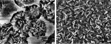 | ||
| Fig. 5 (a) SEM images of HACs converted from BGCs after hydrothermal reaction in SBF for different time: (a) 2 h and (b) 2 days. | ||
In addition, the reaction mediums have great effects on the morphology and crystal orientation of HA. If the reaction medium is not SBF but deionized water, the obtained products are the rod-like particles with a poor crystal orientation (Fig. 6). The corresponding ED pattern in Fig. 6d indicates that these nanorods are HA crystals, too. The reasons that the reaction mediums affect the morphology and crystal orientation of HA nanorods are ascribed to the different supersaturations. The formation process of HA crystals on the coatings can be divided into two stages, including nucleus formation and nucleus growth. The velocity of nucleation is formulated:
| W = K·U | (1) |
| V = (D/S)·O·P | (2) |
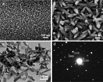 | ||
| Fig. 6 (a and b) SEM images, (c) TEM and (d) corresponding ED pattern of HACs converted from BGCs after hydrothermal reaction in deionized water. | ||
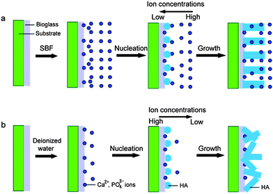 | ||
| Fig. 7 Illustration of formation strategy of HA nanorods after soaking the BGCs in the different reaction mediums: (a) SBF; (b) deionized water. | ||
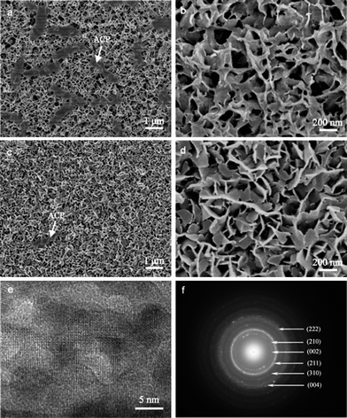
Besides the reaction time and reaction mediums, the reaction temperatures and pressures have great effects on the morphologies of HA coatings. As we know, the SBF immersion tests are often used to investigate the great in vitro bioactivity of the BGCs. After soaking the BGCs in SBF at 37 °C for 12 h, plate-like apatite particles deposit uniformly on their surfaces (Fig. 8). The width and thickness of HA plates are 100–200 nm and ∼20 nm, respectively. Moreover, the gel-like materials due to amorphous calcium phosphate (ACP) are observed in Fig. 8a. The HA layers on the BGCs are so thin that the characteristic peaks cannot be detected in the XRD pattern. With increasing the immersion time from 12 h to 24 h in SBF, the amount of gel-like materials decreases (Fig. 8c), suggesting that more ACP is transformed into HA. It is noted that these plates are composed of many HA nanocrystals and amorphous phases, as confirmed by the TEM images (Fig. 8e). The corresponding ED pattern in Fig. 8f shows clearly visible diffraction rings, whose interplanar spacings are in good agreement with the characteristic spacings of HA.
The HACs and SHACs exhibit the different morphologies (Fig. 1 and 8), which are attributed to the different formation mechanisms under the different reaction temperatures and pressures. The BGCs possess the lower solubility at low temperatures and pressures than at high temperatures and pressures. After soaking the BGCs in SBF at 37 °C and normal pressure, less Ca2+ and PO43− ions are released from the bioglass. The low concentrations of the Ca2+ and PO43− ions in SBF tend to form the calcium-deficient HA with the plate-like or particle shapes, as confirmed by the previous reports.11 Up to now, the accepted mechanism is that the ACP is formed firstly on the BGCs followed by the crystallization into the HA nanocrystals.11a The produced HA nanocrystals aggregate to form the plate-like structure, as shown in Fig. 8. At the same time, part of the ACP is remained among the HA nanocrystals. Under the hydrothermal conditions, more Ca2+ and PO43− ions are released from the BGCs. The great concentrations of Ca2+ and PO43− ions tend to improve the rates of crystal growth (eqn (2)), and assist the formation of HA single crystals with the rod-like structure along the c-axis direction (Fig. 2). In short, the HA plates formed on the BGCs in SBF at 37 °C and normal pressure are due to the aggregates of HA nanocrystals, while the HA rods formed on the BGCs in SBF at hydrothermal conditions are originated from their single crystal structure.
3.4 In vitro bioactivity of HACs
It is believed that the prerequisite for biocoatings to bond to living bone is the formation of a biologically active apatite layer on the coating surfaces in the body. The in vitro assessment of in vivo bone-forming activity is typically carried out by soaking biomaterials in SBF and monitoring the formation of bone-like apatite on the surfaces.12Fig. 1b and c shows that the HA crystals in the HACs exhibit the rod-like structure perpendicular to the surfaces. After soaking the HACs in SBF at 37 °C for 12 h, abundantly bone-like apatite deposits on the surfaces (Fig. 9a). High-resolution SEM image in Fig. 8b indicates that the apatite nanocrystals formed in SBF are also plate-like with the thickness of about 50 nm. At the same time, the gel-like materials due to amorphous calcium phosphate (ACP) are observed in Fig. 9. The obviously different morphologies of the HACs before and after soaking in SBF suggest that the HACs have a good in vitro bioactivity, which may be attributed to the following reasons. Firstly, the HA in the HACs possess the low crystallinity (Fig. 3b), which increase the solubility both in vitro and in vivo tests. The dissolution of HA increases the level of supersaturation in SBF, and thus increases the velocities of nucleation and growth of bone-like apatite nanocrystals. Secondly, the hydroxyl groups in the HACs can act as the active sites for the nucleation of bone-like apatite. Thirdly, after soaking the HACs in SBF, dissolution of crystal planes with higher surface energies is more favorable to reduce the surface energy, and reprecipitation takes place preferentially in the c-plane because of the lowest surface energy. As compared with the randomly oriented HA coatings, the c-axis oriented HA crystals on the HACs are likely to promote preferentially oriented growth through a cyclic process of dissolution and re-precipitation, resulting in the good in vitro bioactivity.5b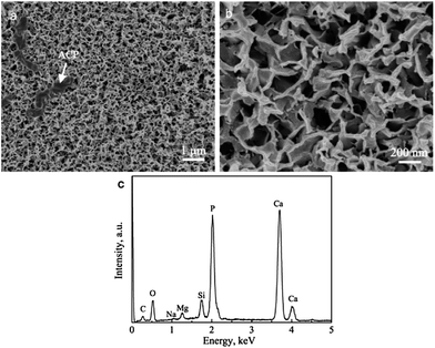 | ||
| Fig. 9 SEM images of HACs after soaking in SBF at 37 °C for 12 h: (a) low magnification; (b) high magnification and (c) corresponding EDS spectrum. | ||
3.5 Biocompatibility of HACs
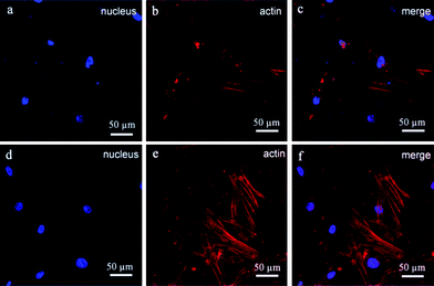
An orthopaedic substitute must have the good biocompatibility with surrounding cells to promote satisfactory osteointegration between the implant and bone tissue. Previous works have shown that the BGCs exhibit great bioactivity and biocompatibility,13 but their chemical component, crystallinity and morphology are different from the minerals of natural bones. In order to obtain the bioactive coatings similar to the minerals of natural bones, the HACs have been fabricated by using the BGCs as precursors (Fig. 1–4). The biocompatibility of the HACs on the cell spreading and proliferation are evaluated by using hBMSCs as a cell model and the BGCs as a control. Fig. 10 shows the LSCM images of the hBMSCs cultured on the HACs and BGCs for 24 h. An actin cytoskeleton and focal adhesion staining kit is used to map the orientation of actin filaments with TRITC phalloidin and labeling nuclei with 4′,6-diamidino-2-phenylindole (DAPI). As compared with the hBMSCs cultured on the BGCs, the cells cultured on the HACs exhibit rearranged cytoskeleton with better-developed stress actin fibers and stronger actin intensity (Fig. 10), suggesting that the HACs show the more excellent cell adhesion and spreading. No evidence of any major deleterious or cytotoxic responses is observed for the HACs.The CCK-8 assays have been performed to continuously compare the proliferation of hBMSCs cultured on the HACs, BGCs and SHACs. As shown in Fig. 11, an increasing trend of cell proliferation in a time dependent manner is observed for the three groups. Interestingly, more viable cells are observed on the HACs than those on the BGCs and SHACs ranging from 1 to 7 days. The hBMSCs exhibit excellent adhesion, spreading and proliferation on the HACs may be attributed to the following reasons. Firstly, the HACs possess the similar chemical composition and crystallinity to the bone minerals (Fig. 1d, 3 and 4). Secondly, the c-axis oriented HA nanorods arrays on the HACs support the initial adhesion, proliferation of the hBMSCs, which have been demonstrated by the previous studies.6b On the contrary, Zhuang et al. have found that the adhesion efficiency of MC3T3-E1 cells decreased with increasing initial a, b-planed orientation degree.14 Although there is a HA layer on the surface of the SHACs, the HA plates are not directional arrangement, resulting in the less viable cells on the SHACs than those on the HACs ranging from 1 to 7 days. Moreover, Liu et al. have found that the ordered fluorapatite crystal surfaces can stimulate the expression of a set of pro-osteogenic transcripts and bone mineralization phenotypic markers of adipose-derived stem cells (ASCs) as compared to metal surfaces at 7 and 21 days.6b
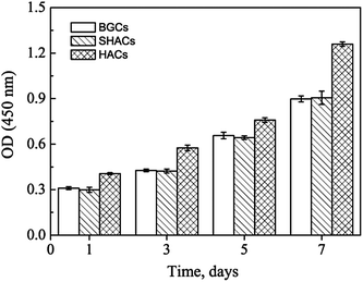 | ||
| Fig. 11 CCK-8 assay results of hBMSCs cultured on the BGCs, SHACs and HACs at different days. The data are represent as the means ± standard deviation; n = 3. | ||
4. Conclusions
The HACs with oriented nanorod arrays have been fabricated by using the BGCs as precursors via a dissolution–precipitation reaction. During the conversion of the BGCs to the HACs, the roles of the BGCs and SBF are similar to the ACP and body fluid in biomineralization of mineral of natural bones, respectively. The obtained HACs possess similar chemical composition, crystallinity and crystallographic texture to the minerals of natural bones. The SBF immersion tests demonstrate that the HACs have excellent in vitro bioactivity, which can promote the formation of bone-like apatite. The biocompatibility tests indicate that hBMSCs have better adhesion, spreading and proliferation on the HACs with oriented nanorod arrays than on the BGCs and SHACs. The excellent in vitro bioactivity and biocompatibility of the HACs suggest that they have great potential for bone implants.Acknowledgements
This research was supported by Key Disciplines of Shanghai Municipal Education Commission (no. J50206), Natural Science Foundation of China (nos 51002095, 51372152 and 30973038), Science and Technology Commission of Shanghai Municipality (no. 12JC1405600), Program of Shanghai Normal University (nos DZL124, DCL201303), Innovation Foundation of Shanghai Education Committee (no. 14ZZ124), and State Key Laboratory for Modification of Chemical Fibers and Polymer Materials, Dong Hua University.Notes and references
- (a) P. S. Liu and J. Song, Biomaterials, 2013, 34, 2442 CrossRef CAS PubMed; (b) L. Sun, S. T. Parker, D. Syoji, X. L. Wang, J. A. Lewis and D. L. Kaplan, Adv. Healthcare Mater., 2012, 1, 729 CrossRef CAS PubMed.
- (a) L. X. Lü, X. F. Zhang, Y. Y. Wang, L. Ortiz, X. Mao, Z. L. Jiang, Z. D. Xiao and N. P. Huang, ACS Appl. Mater. Interfaces, 2013, 5, 319 CrossRef PubMed; (b) Y. Liu, J. Huang and H. Li, J. Mater. Chem. B, 2013, 1, 1826 RSC; (c) J. D. Chen, Y. J. Wang, K. Wei, S. H. Zhang and X. T. Shi, Biomaterials, 2007, 28, 2275 CrossRef CAS PubMed; (d) S. Yang, H. He, L. Wang, X. Jia and H. Feng, Chem. Commun., 2011, 47, 10100 RSC; (e) F. Chen, Y.-J. Zhu, X.-Y. Zhao, B.-Q. Lu and J. Wu, CrystEngComm, 2013, 15, 4527 RSC; (f) Z. Y. Zou, X. G. Liu, L. Chen, K. L. Lin and J. Chang, J. Mater. Chem., 2012, 22, 22637 RSC.
- (a) P. Y. Chen, D. Toroian, P. A. Price and J. McKittrick, Calcif. Tissue Int., 2011, 88, 351 CrossRef CAS PubMed; (b) F. Nudelman, K. Pieterse, A. George, P. H. H. Bomans, H. Friedrich, L. J. Brylka, P. A. J. Hilbers, G. de With and N. A. J. M. Sommerdijk, Nat. Mater., 2010, 9, 1004 CrossRef CAS PubMed.
- M. J. Olszta, X. Cheng, S. S. Jee, R. kumar, Y. Y. Kim, M. J. Kaufman, E. P. Douglas and L. B. Gower, Mater. Sci. Eng., R, 2007, 58, 77 CrossRef PubMed.
- (a) H. R. Wenk and F. Heidelbach, Bone, 1999, 24, 361 CrossRef CAS; (b) H. Kim, R. P. Camata, S. Chowdhury and Y. K. Vohra, Acta Biomater., 2010, 6, 3234 CrossRef CAS PubMed.
- (a) N. Almora-Barrios, K. F. Austen and N. H. De Leeuw, Langmuir, 2009, 25, 5018 CrossRef CAS PubMed; (b) J. Liu, X. Wang, Q. Jin, T. Jin, S. Chang, Z. Zhang, A. Czajka-Jakubowska, W. V. Giannobile, J. E. Nör and B. H. Clarkson, Biomaterials, 2012, 33, 5036 CrossRef CAS PubMed.
- (a) E. A. dos Santos, M. S. Moldovan, L. Jacomine, M. Mateescu, J. Werckmann, K. Anselme, P. Mille and H. Pelletier, Mater. Sci. Eng., B, 2010, 169, 138 CrossRef CAS PubMed; (b) X. Liu, K. Lin, R. Qian, L. Chen, S. Zhuo and J. Chang, Chem.–Eur. J., 2012, 18, 5519 CrossRef CAS PubMed; (c) G. Wang, Z. Lu, X. Zhao, A. Kondyurin and H. Zreiqat, J. Mater. Chem. B, 2013, 1, 2455 RSC; (d) J. Liu, T. C. Jin, S. Chang, A. Czajka-Jakubowska and B. H. Clarkson, J. Biomed. Mater. Res., Part A, 2011, 96, 528–534 CrossRef CAS PubMed.
- (a) D. Dallari, L. Savarino, U. Albisinni, P. Fornasari, A. Ferruzzi, N. Baldini and S. Giannini, Biomaterials, 2012, 33, 72 CrossRef CAS PubMed; (b) M. Manzano, D. Lozano, D. Arcos, S. Portal-Nunez, C. L. Orden, P. Esbrit and M. Vallet-Regi, Acta Biomater., 2011, 7, 3555 CrossRef CAS PubMed.
- (a) C. B. Baddiel and E. E. Berry, Spectrochim. Acta, 1966, 22, 14076 CrossRef; (b) Q. Shi, J. Wang, J. Zhang, J. Fan and G. D. Stucky, Adv. Mater., 2006, 18, 1038 CrossRef CAS; (c) Y. Zhu and S. Kaskel, Microporous Mesoporous Mater., 2009, 118, 176 CrossRef CAS PubMed; (d) P. Yang, Z. Quan, Z. Hou, C. Li, X. Kang, Z. Cheng and J. Lin, Biomaterials, 2009, 30, 4786 CrossRef CAS PubMed.
- (a) H. B. Weiser and A. P. Bloxsom, J. Phys. Chem., 1924, 28, 26 CrossRef CAS; (b) H. B. Weiser and W. O. Milligan, J. Phys. Chem., 1932, 36, 1950 CrossRef CAS.
- (a) I. Izquierdo-Barba, D. Arcos, Y. Sakamoto, O. Terasaki, A. López-Noriega and M. Vallet-Regí, Chem. Mater., 2008, 20, 3191 CrossRef CAS; (b) H. X. Tang, Y. P. Guo, D. C. Jia and Y. Zhou, Microporous Mesoporous Mater., 2010, 131, 1 CrossRef PubMed.
- (a) T. Kokubo and H. Takadama, Biomaterials, 2006, 27, 2907 CrossRef CAS PubMed; (b) Y. P. Guo, Y. Zhou, D. C. Jia and Q. C. Meng, Acta Biomater., 2008, 4, 932 CrossRef PubMed; (c) T. Akazawa, M. Murata, J. Hino, F. Nagano, T. Shigyo, T. Nomura, H. Inano, K. Itabashi, T. Yamagishi, K. Nakamura, T. Takahashi, S. Iida and H. Kashiwazaki, Appl. Surf. Sci., 2012, 262, 51 CrossRef CAS PubMed.
- (a) C. X. Xu, P. Q. Su, X. F. Chen, Y. C. Meng, W. H. Yu, A. P. Xiang and Y. J. Wang, Biomaterials, 2011, 32, 1051 CrossRef CAS PubMed; (b) Q. Z. Chen, J. L. Xu, L. G. Yu, X. Y. Fang and K. A. Khor, Mater. Sci. Eng., C, 2012, 32, 494 CrossRef CAS PubMed.
- Z. Zhuang, T. J. Fujimi, M. Nakamura, T. Konishi, H. Yoshimura and M. Aizawa, Acta Biomater., 2013, 9, 6732 CrossRef CAS PubMed.
Footnote |
| † W. Chen and T. Long contributed equally to this work. |
| This journal is © The Royal Society of Chemistry 2014 |

