
Tri- and tetradentate copper complexes: a comparative study on homogeneous and heterogeneous catalysis over oxidation reactions†
Salam J. J.
Titinchi
*a,
Gavin
Von Willingh
a,
Hanna S.
Abbo
a and
Rajendra
Prasad
b
aUniversity of the Western Cape, Cape Town, South Africa. E-mail: stitinchi@uwc.ac.za; Fax: +27 21 959 3055; Tel: +27 21 959 2217
bFiji National University, Lautoka, Fiji
First published on 15th August 2014
Abstract
Catalytic liquid phase oxidation of benzene, phenol, styrene and cyclohexene was carried out using Schiff-base copper(II) complexes of ligands 4-(2-amino-ethylimino)-pent-2-en-2-ol (HL1) and (4-[2-(3-hydroxy-1-methyl-but-2-enylideneamino)-ethylimino]-pent-2-en-2-ol (H2L2) in homogenous and heterogeneous media. Treatment of Cu-Y-zeolite with ligand solutions led to insertion of the flexible ligands into zeolite super-cages and in situ formation of encapsulated copper(II) complexes inside the zeolite cavities. The encapsulated complexes [Cu(L2)]-Y and [CuCl(L1)]-Y were characterized using FT-IR, UV-vis, Raman spectrometry, BET, XRD and thermal analysis techniques, substantiating the formation of intrazeolitic copper complexes without loss in the crystallinity for the zeolite framework structure. Catalytic activities of the encapsulated complexes and their “neat” analogues were investigated for the oxidation of benzene, phenol, styrene and cyclohexene using H2O2 as an oxidant. Conversion efficiencies were optimized by varying reaction parameters, i.e. temperature, oxidant concentration, catalyst amounts and solvent nature and volume. In all oxidation reactions, the neat complexes exhibited higher conversion efficiency than the encapsulated complexes at shorter reaction times under optimum reaction conditions. Although the zeolite-encapsulated complexes required longer reaction times to reach maximum conversion, they were beneficial towards enhancing the selectivity and TOF values as compared to the neat analogues. Furthermore, the heterogeneous catalytic system can be recovered and reused without activity loss. The possible reaction pathway for phenol oxidation catalysed by these complexes was investigated by UV-visible spectroscopy and electrochemical methods.
1. Introduction
Owing to their high surface area, thermal stability, tuneable chemical properties and amphiphilic and environmentally friendly nature, zeolites are utilized in different industrial processes ranging from simple drying of liquids to more complicated catalytic reactions.1,2 Microporous zeolite crystals possess channels and cages regularly extended over the entire crystal and thereby enable a large surface area. Adsorption of molecules, particularly organic molecules, occurs on both the external and the internal surfaces of a zeolite crystal and leads to molecular alignments and imposition of conformational restrictions in them.2,3 These changes in guest molecules form the basis of catalytic applications of zeolites. Starting from early 1960’s application in petrochemical industries, the catalytic chemistry of zeolites has undergone tremendous expansion into synthesis of fine chemicals and environmental applications.4–6Catalysis by metal nanoparticles known as “semi-heterogeneous” nano-catalysis receives wide recognition nowadays as it is considered to be at the frontier between homogeneous and heterogeneous catalysis and has been used for many organic transformations.7,8 On the other hand, by undergoing metal ion oxidation state changes, transition metal complexes directly drive or catalyse many redox processes.
In recent years, zeolites modified with transition metal complexes are increasingly being used in catalysing a variety of important redox reactions.4 Encapsulation of transition metal complexes such as Fe(III) and Cu(II) complexes inside the Y-zeolite super-cages is a promising field of research as new heterogeneous redox catalysts.9–12 Unlike homogeneous catalytic oxidation, heterogeneous catalytic reactions involving solid catalysts are more attractive as they facilitate high turnover and catalyst recoverability and thus are eco-friendly. The encapsulated transition metal complexes combine the advantages of heterogeneous catalysts with ease of separation from the reaction mixture with that of homogeneous catalysts in terms of quantity and contact area. It is therefore not surprising that encapsulated transition metal complexes are used in various catalytic reactions, i.e. oxidation, alkylation, dehydrogenation, cyclization, amination, acylation, isomerisation, rearrangement, etc., in major industrial processes.4–6,13–21
Recently, we have investigated the catalytic activity of a number of metal complexes, zeolite-encapsulated metals and macrocycle complexes for different oxidation reactions.19,22–26
H2O2 is a strong oxidant and is very useful in producing dihydroxybenzenes. It is a stable and environmentally friendly oxidant, producing only water as a by-product. The main disadvantage of H2O2 is that it is less reactive as compared to organic peroxides and thus requires catalysts to facilitate faster reactions.
In this paper, as an extension of our previous studies, we report the synthesis and catalysis by zeolite-encapsulated Schiff-base copper(II) complexes of 4-(2-amino-ethylimino)-pent-2-en-2-ol and (4-[2-(3-hydroxy-1-methyl-but-2-enylideneamino)-ethylimino]-pent-2-en-2-ol ligands (Scheme 1) and their “neat” complexes. There have been three main approaches to synthesizing these ship-in-the-bottle chelate complexes, namely, the (i) flexible ligand method,27,28 (ii) template synthesis method29,30 and (iii) zeolite synthesis method.31,32
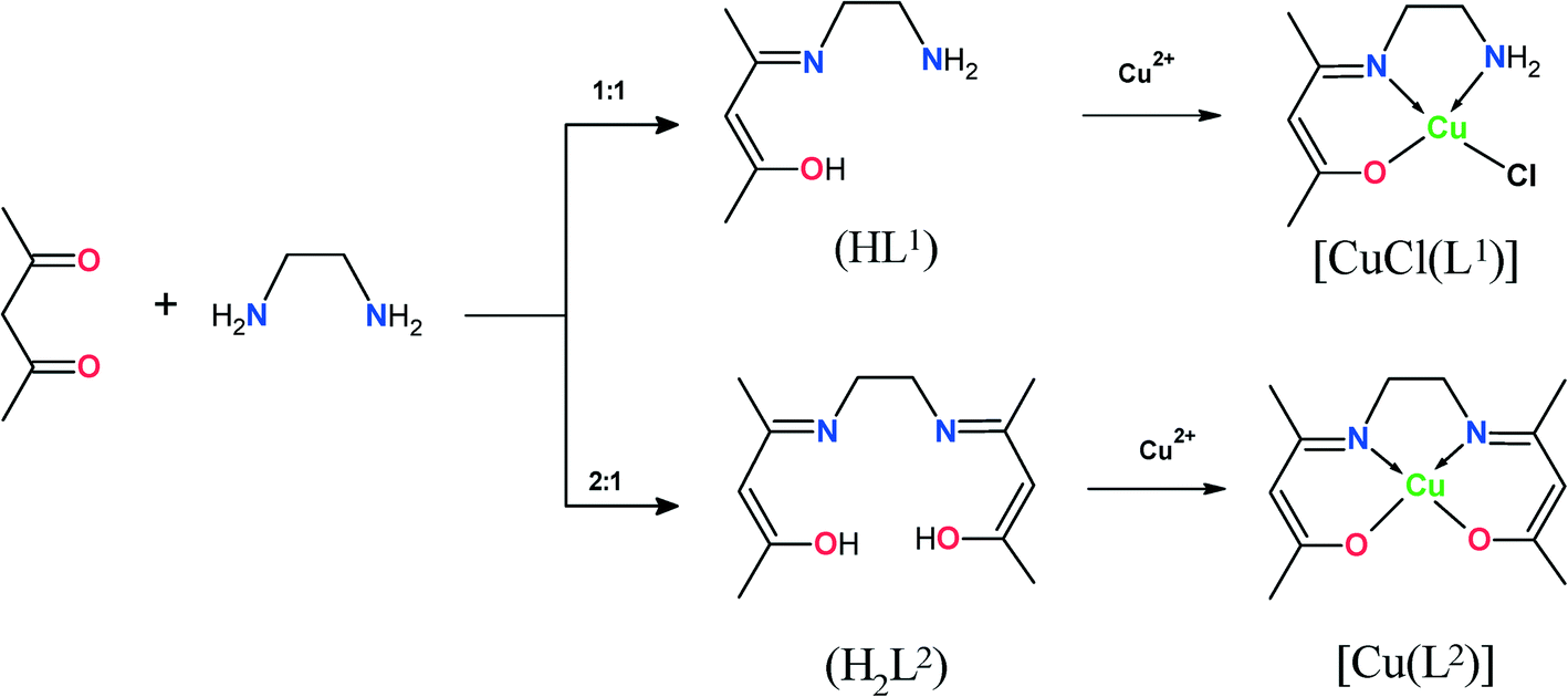 | ||
| Scheme 1 Synthesis of ligands and their Cu(II) complexes. | ||
The first method, which is more convenient, was used in this study. Ligands were diffused through the voids in the zeolites and the complexes were formed in situ inside the zeolite cages, forming bulky and rigid structures, making it difficult to escape from the cage. Unencapsulated, i.e. neat, complexes were also synthesized and characterized. Both encapsulated and neat complexes were screened for catalytic oxidation of phenol, benzene, styrene and cyclohexene. The catalytic efficacy and selectivity for the products were investigated, and reaction conditions were optimized to obtain maximized product yield.
2. Results and discussion
2.1 Synthesis of [CuCl(L1)] and [Cu(L2)] and their corresponding encapsulated complexes
Ligands HL1 and H2L2 were synthesised according to the literature procedure37 (Scheme 1). The reactions of HL1 and H2L2 with CuCl2·2H2O in ethanol gave moderate yields of the corresponding complexes [CuCl(L1)] and [Cu(L2)]. The encapsulation of Cu(II) complexes in the nano-cavities of zeolite-Y was carried out by using a flexible ligand method. The ligand with dimensions less than the zeolite pore openings of 7.4 Å readily diffused through the zeolite super-cages, followed by complexation with copper ions. Complexation of ligands HL1 and H2L2 with Cu(II) ion-exchanged zeolite was accompanied by a colour change to pale green and pale orange, respectively. The crude mass was finally purified by Soxhlet extraction in acetonitrile to remove excess ligand that remained uncomplexed in the cavities of the zeolite as well as ligand that was located on the surface of the zeolite along with free complex, if any. The uncomplexed metal ions present in the zeolite were removed by exchange with aqueous 0.01 M solution of NaCl. The resulting encapsulated complex was filtered, washed with distilled water to remove any chloride ions present, and dried at 150 °C for 24 h. The obtained solid residue was filtered, washed with hot distilled water, and then dried at 120 °C in air for several hours.2.2 Characterization
The percentage of copper content in the encapsulated catalysts was determined by ICP. Values observed were low and indicated low w/w loading of zeolites with copper(II) complexes. These encapsulated catalysts were further characterized by FT-IR and electronic spectra, thermal analysis and X-ray powder diffraction analysis (vide infra). Results are in support of the formation of encapsulated copper complexes inside the cavities of the zeolite.The weak broad band around 3400 cm−1 ascribed to ν(OH) vibrations observed in the free ligands disappeared upon complexation, indicating involvement of deprotonated OH groups in coordination with copper(II) ions. HL1 and H2L2 ligands exhibit a strong band at 1559 and 1570 cm−1, respectively, which are attributed to (C![[double bond, length as m-dash]](https://www.rsc.org/images/entities/char_e001.gif) N) stretching vibrations in both ligands. This band was lowered by ca. 40 cm−1 upon complexation, as a result of coordination of the azomethine nitrogen with the metal ion. Both complexes as well as encapsulated complex zeolites exhibited new moderate intensity bands in the low-frequency region between 350 and 500 cm−1 due to ν(M–O) and ν(M–N) stretching vibrations. This is in further support of coordination of nitrogen and oxygen to the metal. The [CuCl(L1)] complex exhibited a band in the 316 cm−1 region assigned to ν(M–Cl).38 This complex also showed two sharp weak bands at 2920 and 2862 cm−1, which are attributed to the free NH2 group.39 The presence of multiple bands of medium intensity in the 2700–2900 cm−1 region is attributed to the ethylene groups of the ligands. On the basis of FTIR data, it is concluded that the Cu metal ion was coordinated to azomethine nitrogen, alcoholic oxygen, the amine group and chloride in [CuCl(L1)] and to the azomethine nitrogen and alcoholic oxygen in [Cu(L2)]. Thus, IR data confirm the encapsulation of complexes in zeolite cavities and are thus in support of the proposed structures.
N) stretching vibrations in both ligands. This band was lowered by ca. 40 cm−1 upon complexation, as a result of coordination of the azomethine nitrogen with the metal ion. Both complexes as well as encapsulated complex zeolites exhibited new moderate intensity bands in the low-frequency region between 350 and 500 cm−1 due to ν(M–O) and ν(M–N) stretching vibrations. This is in further support of coordination of nitrogen and oxygen to the metal. The [CuCl(L1)] complex exhibited a band in the 316 cm−1 region assigned to ν(M–Cl).38 This complex also showed two sharp weak bands at 2920 and 2862 cm−1, which are attributed to the free NH2 group.39 The presence of multiple bands of medium intensity in the 2700–2900 cm−1 region is attributed to the ethylene groups of the ligands. On the basis of FTIR data, it is concluded that the Cu metal ion was coordinated to azomethine nitrogen, alcoholic oxygen, the amine group and chloride in [CuCl(L1)] and to the azomethine nitrogen and alcoholic oxygen in [Cu(L2)]. Thus, IR data confirm the encapsulation of complexes in zeolite cavities and are thus in support of the proposed structures.
Raman spectroscopy was employed to provide identification of copper Schiff-base complexes present in zeolite cavities, with the 1200–1700 cm−1 bands being most informative. It is known that Raman spectra of zeolite-Y show one intense band at 500 cm−1 and two other low-intensity bands (800 and 1100 cm−1) that are assigned to Si–O–Si bending and symmetric νs(SiO4) and asymmetric νas(SiO4) stretching vibrations, respectively.41,42 The Raman spectra of the [CuCl(L1)]-Y catalyst, recorded in acetonitrile solution in the range 50–4000 cm−1, are shown in Fig. S1.† It can be seen in the spectra of [CuCl(L1)]-Y that strong bands appear in the 1200–1700 cm−1 region due to the presence of an encapsulated complex inside the zeolite matrix. The presence of a Cu–Cl band at 291 cm−1 confirmed the presence of [CuCl(L1)] encapsulated in the Y-zeolite super-cages.43
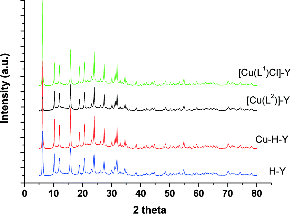 | ||
| Fig. 1 XRD patterns of encapsulated catalysts and their parent zeolites. | ||
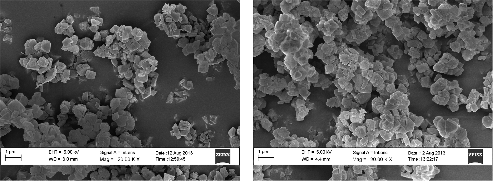 | ||
| Fig. 2 Scanning electron micrographs of Cu-Y (left) and [Cu(L2)]-Y (right). | ||
| Catalyst | Colour | Metal content (wt%) | Langmuir surface area (m2 g−1) | Pore volume (mL g−1) | Average pore size (Å) |
|---|---|---|---|---|---|
| H-Y | White | — | 780 | 0.48 | 42.50 |
| Cu-H-Y | Light blue | 0.21 | 476 | 0.36 | 31.33 |
| [CuCl(L1)]-Y | Pale brown | 0.13 | 452 | 0.33 | 30.43 |
| [Cu(L2)]-Y | Pale green | 0.18 | 439 | 0.34 | 30.06 |
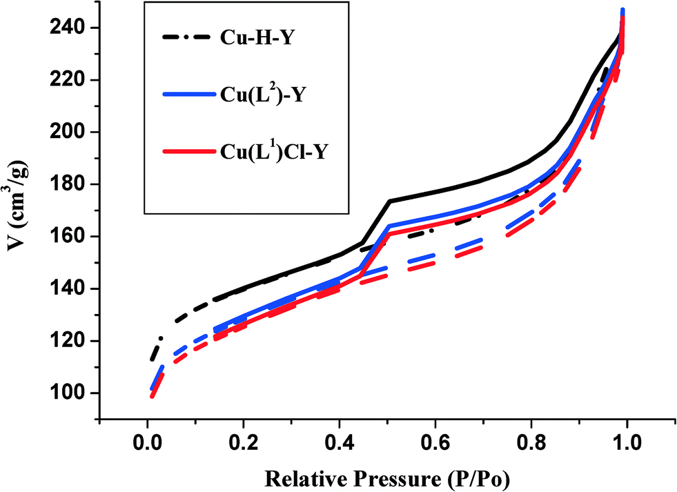 | ||
| Fig. 3 N2 adsorption/desorption isotherms of Cu-H-Y, [CuCl(L1)]-Y and [Cu(L2)]-Y. | ||
It has to be noted that Cu2+ incorporation leads to a more pronounced decrease in the surface area. As the reaction was carried out in aqueous medium, [Cu(H2O)6]2+ ions were likely to have been incorporated. The reaction of HL1 and H2L2 with Cu-H-Y leads to the formation of [CuCl(L1)] and [Cu(L2)] complexes with only a marginal decrease in surface area and pore volume compared to Cu-H-Y. This is clearly due to a marginal increase in complex molecular volume.
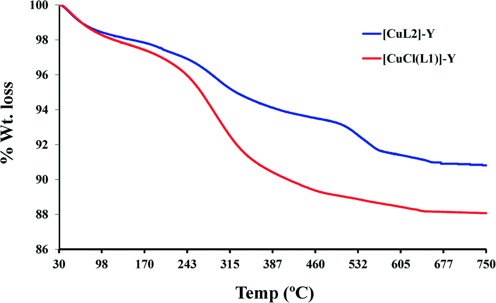 | ||
| Fig. 4 Thermograms for the encapsulated complexes. | ||


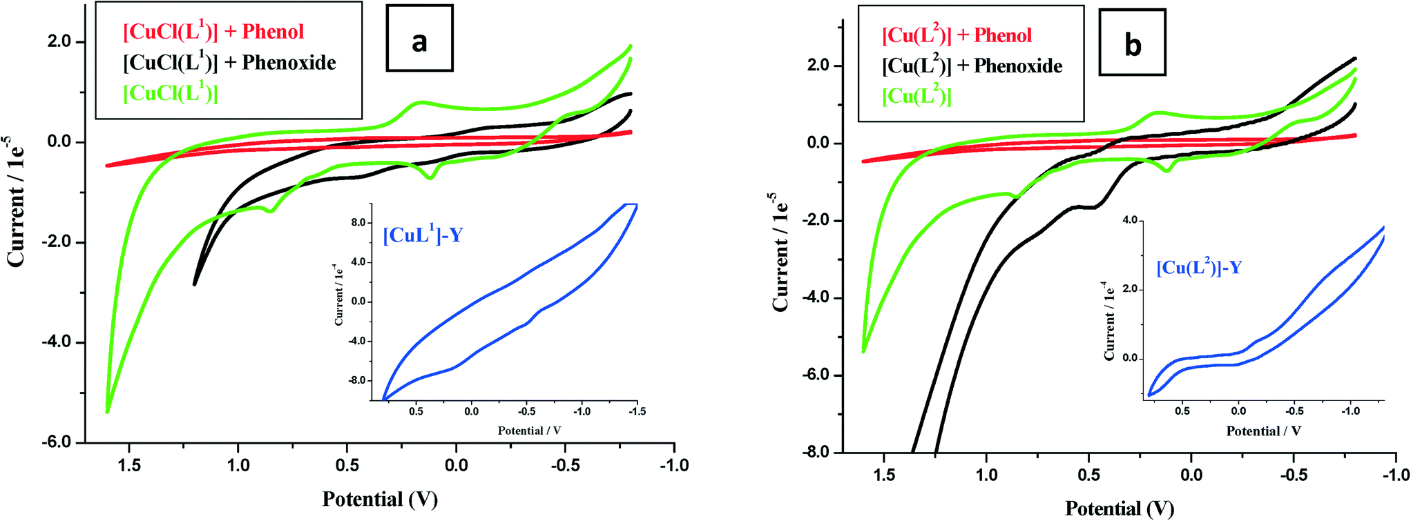 | ||
| Fig. 5 Cyclic voltammograms in 0.1 M LiClO4 solution. (a) 1 ml (0.01 M) [CuCl(L1)], [CuCl(L1)] + 1 ml phenol (0.01 M in dry MeCN), [CuCl(L1)] + phenoxide (0.01 M in water). Inset: [CuCl(L1)]-Y in dry acetonitrile. (b) 1 ml (0.01 M) [Cu(L2)], [Cu(L2)] + 1 ml phenol (0.01 M in dry MeCN) and [Cu(L2)] + phenoxide (0.01 M in water). Inset: [Cu(L2)]-Y in dry acetonitrile at a scan rate of 100 mV s−1. | ||
The second oxidation arose from ligand-centered electro-oxidation, confirmed by similar potentials observed for the ligand (Fig. 5a and b).
Electrochemical oxidation catalysis by the encapsulated complexes was investigated using the cyclic voltammetry (CV) technique. The current voltage characteristics were recorded in blank runs for phenol and sodium phenoxide (0.01 M) and similarly in the presence of 0.01 M of the complex in dry acetonitrile. Modification in the nature and position of the oxidation waves of the substrate in the presence of the catalyst was carefully recorded. Following electro-oxidation, the copper electron configuration changes from d9 to d8, and thus, the square planar configuration becomes further stabilized by loss of two coordinated ligands. This configuration formed transiently at the electrode surface and provided the catalytic centre. The voltammograms of phenol and phenoxide ions in the presence of complexes and ligands are shown in Fig. 5. It is seen that ligand voltammograms did not change, while copper complexes [CuCl(L1)] and [Cu(L2)] showed a marked increase in anodic peaks particularly in the presence of phenoxide ions (Fig. 5a and b).
| Complex | λ m/nm (ε/M−1 cm−1) |
|---|---|
| HL1 | 320 |
| H2L2 | 322, 304 (sh) |
| [CuCl(L1)] | 224, 305, 324 (sh), 540 |
| [CuCl(L1)]-Y | 200, 280, 602, 589 |
| [Cu(L2)] | 204, 226 (sh), 278, 322, 342 (sh), 546 |
| [Cu(L2)]-Y | 200, 274 (sh), 309, 616 |
A weak and broad absorption band at 610–650 nm was also observed in both encapsulated complexes when highly concentrated Nujol mull paste was used and arose due to d–d transition in the complex. The electronic spectral data of the Cu(II) complex-Y compare closely with that of pure complexes and are indicative of a square-planar structure present in the cavity of the zeolite.48
2.3 Reaction pathway of copper(II) catalyst systems
In order to understand the reaction pathway and intermediate species formed during oxidation of the substrates, methanolic solutions of neat copper(II) complexes were treated with a methanolic solution of H2O2 (dropwise), and the progress of the reaction was monitored by electronic absorption spectroscopy.As shown in Fig. 6a and b, addition of one drop of 30% H2O2 in methanol (10−4 M) to a solution of [CuCl(L1)] or [Cu(L2)] dissolved in methanol resulted in a significant increase in the intensity of the band appearing at ~220 nm. Simultaneously, the other bands between 278 and 340 nm also experienced a slight increase in intensities. On the other hand, the intensities of the d–d bands in the 550–880 nm region decreased. Further addition of H2O2 did not alter the peak's intensity. Spectral changes in the presence of H2O2 indicate formation of intermediate peroxo species at the Cu(II) metal centre in the complex. These intermediates are expected to participate and transfer the oxygen atoms to the substrates to give oxidized products.34
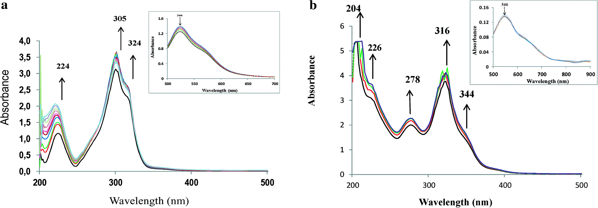 | ||
| Fig. 6 a. Spectral changes obtained on stepwise addition of 10−4 M methanolic solution of H2O2 to [CuCl(L1)]. The inset shows the visible region. b. Spectral changes obtained on stepwise addition of 10−4 M methanolic solution of H2O2 to [Cu(L2)]. The inset shows the visible region. | ||
2.4 Oxidation studies
To determine suitable reaction conditions for maximum conversion of substrates, the effects of temperature, catalyst amount, solvent volume, H2O2 concentration and the nature of the solvent were investigated using [Cu(L2)]-Y as a representative catalyst. Optimization studies were carried out for hydroxylation of phenol, and the same conditions were used in the oxidation of other substrates as well as for [CuCl(L1)]-Y.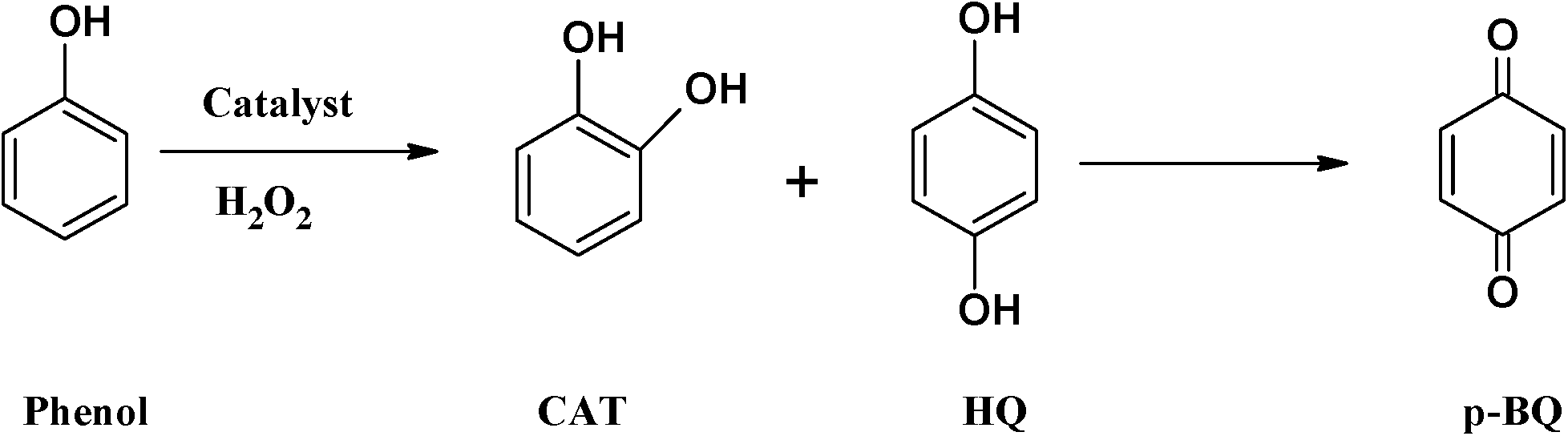 | ||
| Scheme 2 Oxidation products for hydroxylation of phenol. | ||
2.4.1.1 Effect of H2O2/phenol molar ratio. In order to determine the effect of H2O2/phenol molar ratio on the oxidation of the substrate, three different molar ratios (0.3
![[thin space (1/6-em)]](https://www.rsc.org/images/entities/char_2009.gif) :1, 1:1 and 2:1) were studied, whilst keeping a fixed amount of phenol (0.025 mol) and catalyst (0.01 g) in 3 ml of MeCN at 70 °C and running the reaction for 24 h (Fig. 7). It was found that increasing the H2O2/phenol ratio from 0.3:1 to 1:1 increased the conversion ~4-fold from 5.1% to 19.5% and led to a slight drop in catechol selectivity after 6 hours. The poor activity of the catalyst at low H2O2/phenol molar ratio could have resulted from decreased concentration of hydroxyl radicals and thus decreased concentration of intermediates.
:1, 1:1 and 2:1) were studied, whilst keeping a fixed amount of phenol (0.025 mol) and catalyst (0.01 g) in 3 ml of MeCN at 70 °C and running the reaction for 24 h (Fig. 7). It was found that increasing the H2O2/phenol ratio from 0.3:1 to 1:1 increased the conversion ~4-fold from 5.1% to 19.5% and led to a slight drop in catechol selectivity after 6 hours. The poor activity of the catalyst at low H2O2/phenol molar ratio could have resulted from decreased concentration of hydroxyl radicals and thus decreased concentration of intermediates.
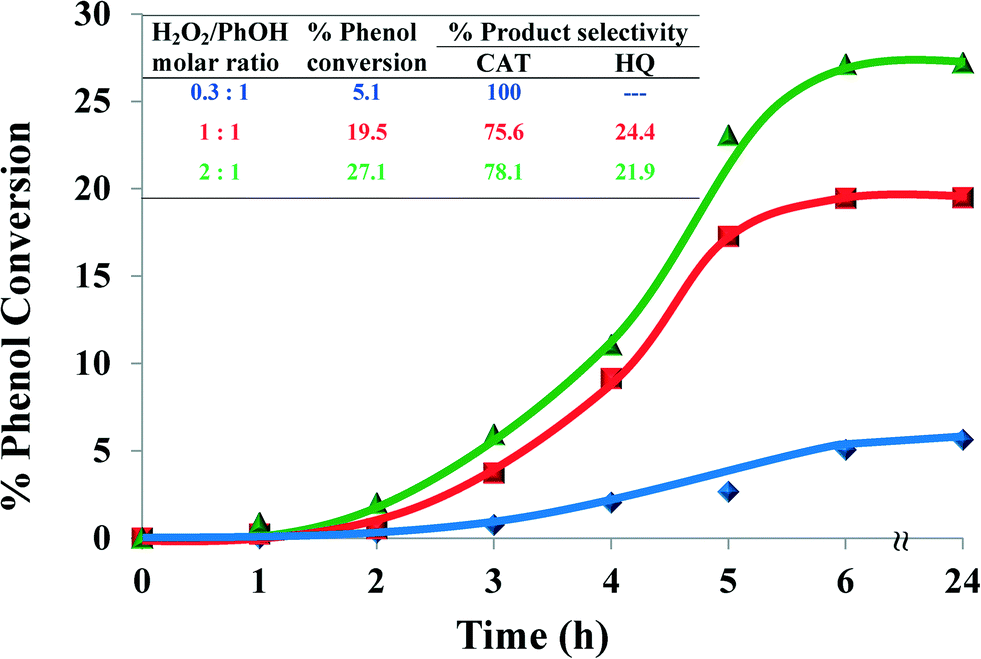 | ||
| Fig. 7 Effect of H2O2/PhOH molar ratio on % phenol conversion over time and product selectivity (inset). Reaction conditions: phenol (2.35 g), [Cu(L2)]-Y (0.010 g), MeCN (3 ml), 70 °C, 6 h. | ||
When the amount of H2O2 was doubled, the percentage conversion was increased to 27.1%. Therefore, the ratio 1:1 was chosen for further studies in order to reduce oxidant consumption.
2.4.1.2 Effect of reaction temperature. The performance of the catalyst was investigated at three different temperatures, viz. 60, 70 and 80 °C whilst keeping all the other parameters constant over a period of 24 h. Fig. 8 shows the effect of temperature on the oxidation of phenol. At a low temperature (60 °C), the reaction showed a low activity but high selectivity for catechol formation. On increasing the temperature to 70 °C, percentage conversion increased 4-fold, with a slight drop in CAT (75.6%) selectivity. Further, by increasing the temperature to 80 °C much higher conversion for phenol hydroxylation was observed. However, % catechol selectivity decreased marginally, while still being the predominant product.
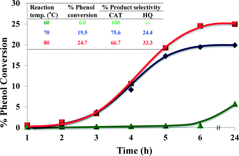 | ||
| Fig. 8 Effect of reaction temperature on % phenol conversion over time and product selectivity (inset). Reaction conditions: phenol (2.35 g), H2O2 (2.83 g), [Cu(L2)]-Y (0.010 g), MeCN (3 ml), 6 h. | ||
It is concluded that at higher temperatures higher conversion may be achieved but at the expense of selectivity (Fig. 8, inset). Also, at higher reaction temperatures a loss of H2O2 efficiency was observed due to the thermal degradation of H2O2.
2.4.1.3 Effect of solvents. The influence of solvent on catalytic activity during hydroxylation of phenol was investigated using five different solvents ranging from polar ethanol, MeCN, ethyl acetate and DCM to non-polar n-hexane, whilst keeping all the other reaction conditions constant. The nature of solvent influences yields, product formation and reaction kinetics in the catalytic reaction. The effect of different solvents on the oxidation of phenol is shown in Fig. 9.
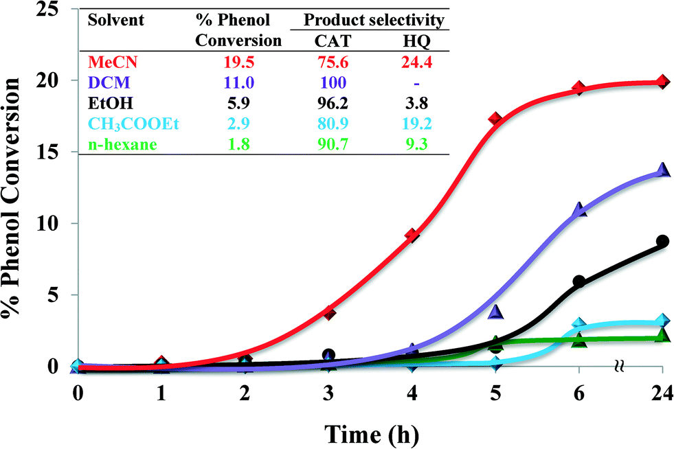 | ||
| Fig. 9 Effect of type of solvents on % phenol conversion over time and product selectivity (inset). Reaction conditions: phenol (2.35 g), H2O2 (2.83 g), [Cu(L2)]-Y (0.010 g), solvent (3 ml), 70 °C, 6 h. | ||
Solvents influence reaction rates by competitive sorption/adsorption in the zeolite super-cages. Polarity, solvation power and the size of the solvent molecules play important roles. The nature of the solvent affected the rate of the reaction as well as the selectivity. Significantly lower oxidation yields were observed in n-hexane (1.8%) and ethyl acetate (2.9%). Amongst all solvents, phenol oxidation was the highest in MeCN (19.5% conversion) over 6 h reaction time. This could possibly be due to MeCN being a coordinating ligand and thus facilitating a five-coordinated catalyst complex, where MeCN occupied one site.25
In dichloromethane (DCM) and n-hexane, reaction mixtures were non-homogeneous and phenol moved to the organic layer whilst the catalyst caused the reaction to occur at the interface. The % phenol conversion in these solvents is arranged in the following decreasing order: MeCN ≫ DCM > ethanol > ethyl acetate > n-hexane. Therefore, MeCN was selected to be the most suitable solvent in these catalytic reactions.
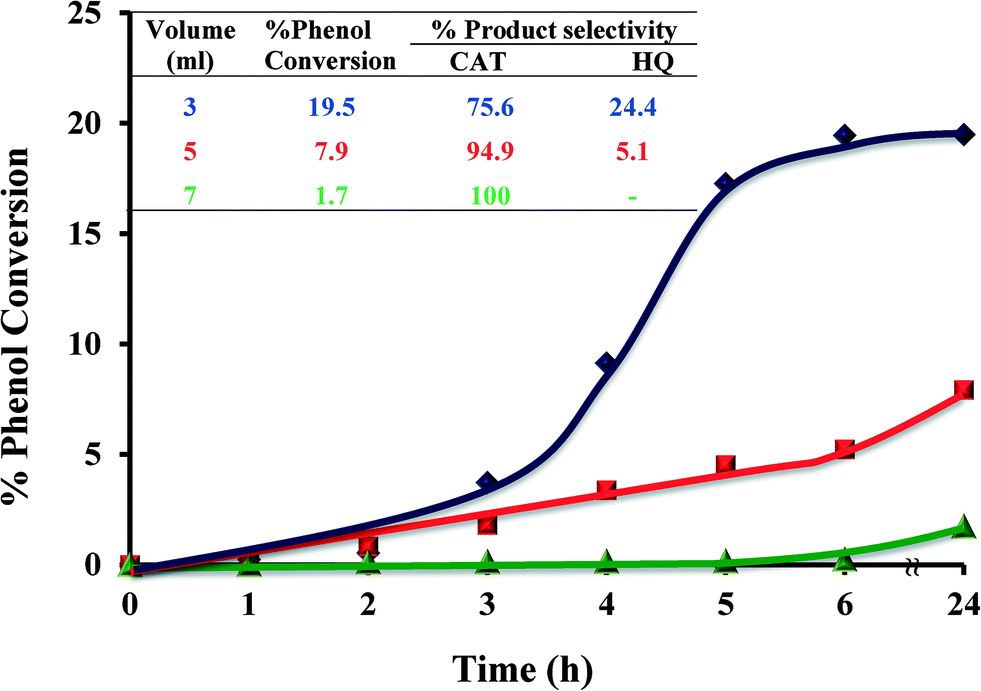
2.4.1.4 Effect of solvent volume. Volume of solvent played an important role in catalyst performance, as shown in Fig. 10. Three different volumes, 3, 5 and 7 ml, were employed and the conversion percentages were determined over time. Increasing the volume of solvent from 3 to 5 ml led to a significant reduction in the overall catalytic conversion from 19.5 to 7.9% over the 6 h time period. Further increasing the volume of the solvent to 7 ml resulted in a dramatic drop (1.7%) in catalytic activity. It is concluded that an increase in solvent volume leads to lowering in percentage phenol conversion.
 | ||
| Fig. 10 Effect of solvent volume on % phenol conversion over time and product selectivity (inset). Reaction conditions: phenol (2.35 g), H2O2 (2.83 g), [Cu(L2)]-Y (0.010 g), MeCN, 70 °C. | ||
Solvent volume highly affects the reaction kinetics. Increase solvent's volume leads to a decrease in reactant concentration in the reaction mixture and thereby lower reaction rates.49
It was also noted that an increase in solvent volume led to an increase in selectivity towards the formation of catechol. Decreasing the solvent volume to below 3 ml resulted in the reaction mixture becoming a slurry and almost no conversion took place.
2.4.1.5 Effect of catalyst amount. The effect of the amount of catalyst on catalytic performance for hydroxylation of phenol is shown in Fig. 11. Three different amounts of catalyst were studied, viz. 0.005, 0.010 and 0.020 g, whilst keeping the other parameters constant. The results indicate that increasing the amount of catalyst from 0.005 g to 0.01 g increased the conversion from 3.4% to 19.5% after 6 hours. Further catalyst amount increase to 0.02 g resulted in increasing the percentage conversion to 27% (Fig. 11, inset).
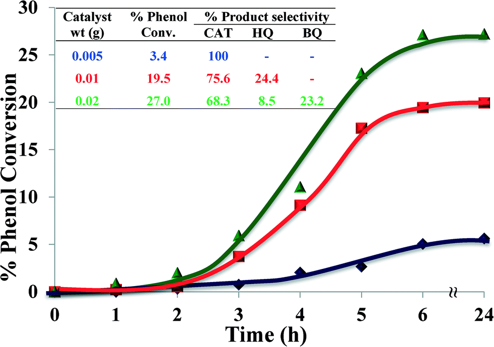 | ||
| Fig. 11 Effect of catalyst amount on % phenol conversion over time and product selectivity (inset). Reaction conditions: phenol (2.35 g), H2O2 (2.83 g), [Cu(L2)]-Y, MeCN (3 ml), 70 °C, 6 h. | ||
The reason for the increased conversion was the availability of larger surface area, thereby facilitating accessibility of catalyst to a large number of reactant molecules.3 The enhancement of phenol conversion as a result of an increase in catalyst amount was partly due to the increase in decomposition rate of H2O2 in the presence of excess catalyst. Therefore, higher conversion of organic substrates was expected.50 A moderate increase in activity at a higher amount of catalyst might possibly be due to chemisorption of the reactants on the surface of isolated catalyst particles, thereby reducing the possibility to interact.
Increasing the amount of catalyst also influenced selectivity towards catechol. 0.005 g of catalyst yielded 100% catechol, whilst increasing the amount of catalyst to 0.01 g caused a drop in catechol selectivity to 75.6%. Upon further increase of catalyst to 0.02 g, catechol formation dropped even further, to 68.3%, besides formation of an over-oxidation product in a significant amount (23%). It is concluded that 0.01 g of catalyst provides better product yield and faster rate of conversion, which is also the appropriate amount for selective conversion.
2.4.1.6 Comparison studies of different copper catalysts. Under optimized reaction conditions, i.e. phenol (0.025 mol), H2O2/phenol molar ratio of 1
:1, catalyst (0.01 g), CH3CN (3 ml) and temperature (70 °C), the ion-exchanged zeolite, encapsulated copper complexes and their neat complexes were tested for hydroxylation of phenol and the results are illustrated in Fig. 12 and Table 3.
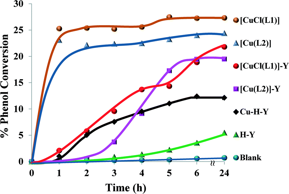 | ||
| Fig. 12 % Phenol conversion vs. time for the different catalysts. Reaction conditions: phenol (2.35 g), H2O2 (2.83 g), catalyst (0.010 g), MeCN (3 ml), 70 °C. | ||
| Catalyst | % Phenol conv. | Selectivity (%) | TOF (h−1) | ||
|---|---|---|---|---|---|
| CAT | HQ | BQ | |||
| a Reaction conditions: phenol (2.35 g), H2O2 (2.83 g), [Cu(L2)]-Y (0.010 g), MeCN (3 ml), 70 °C, 6 h. TOF: turnover frequency; moles of phenol converted per mole of metal (in the solid catalyst) per hour. | |||||
| [CuCl(L1)] | 28.2 | 61.9 | 38.1 | — | 28 |
| [Cu(L2)] | 25.0 | 62.5 | 37.5 | — | 29 |
| [CuCl(L1)]-Y | 20.9 | 73.1 | 19.1 | 7.9 | 3074 |
| [Cu(L2)]-Y | 19.5 | 75.6 | 24.4 | — | 2868 |
| Cu-H-Y | 12.4 | 73.9 | 26.9 | — | 1823 |
| H-Y | 3.9 | 95.8 | 4.2 | — | 574 |
| Blank | 0.6 | 94.2 | 5.8 | — | — |
It was observed that the reaction was slow in the first 3 hours using the encapsulated Cu catalysts (<10%), but an improvement was achieved afterwards. The neat Cu complexes displayed a higher activity than their respective encapsulated counterparts, showing maximum percentage conversion (22–27%) after 1 h. This may be attributed to the presence of a larger number of active metal centres than in the encapsulated complexes for the same amount of catalyst.
It is clear from Table 3 that both encapsulated Cu catalysts show higher percentage selectivity towards catechol formation than the corresponding neat complexes. Upon increasing the reaction time from 6 to 24 h, a small variation in % phenol conversion and product selectivity was observed.
A blank reaction carried out under similar optimum conditions showed no activity. On the other hand, the ion-exchanged zeolite, Cu-H-Y, showed a moderate activity compared to the encapsulated complexes. Thus, it can clearly be seen that the new encapsulated catalysts were somewhat less active but gave very high turnover frequency (TOF) values in comparison to the homogenous catalysts. Therefore, the catalytic activity of these materials can be arranged in the following order: [CuCl(L1)] > [Cu(L2)] > [CuCl(L1)]-Y > [Cu(L2)]-Y > Cu-H-Y.
| Catalyst | % Benzene conversion | % Selectivity | ||
|---|---|---|---|---|
| PhOH | CAT | HQ | ||
| a Reaction conditions: benzene (1.93 g), H2O2 (2.83 g), catalyst (0.010 g), CH3CN (3 ml), 70 °C, 6 h. TOF: turnover frequency; moles of benzene converted per mole of metal (in the solid catalyst) per hour. | ||||
| [CuCl(L1)] | 9.6 | 78.0 | 16.7 | 5.3 |
| [Cu(L2)] | 6.7 | 73.8 | 6.4 | 16.5 |
| [CuCl(L1)]-Y | 6.7 | 100 | — | — |
| [Cu(L2)]-Y | 5.6 | 100 | — | — |
| Cu-H-Y | 2.6 | 95.1 | 4.9 | — |
| H-Y | 1.0 | 100 | — | — |
| Blank | 0.5 | 100 | — | — |
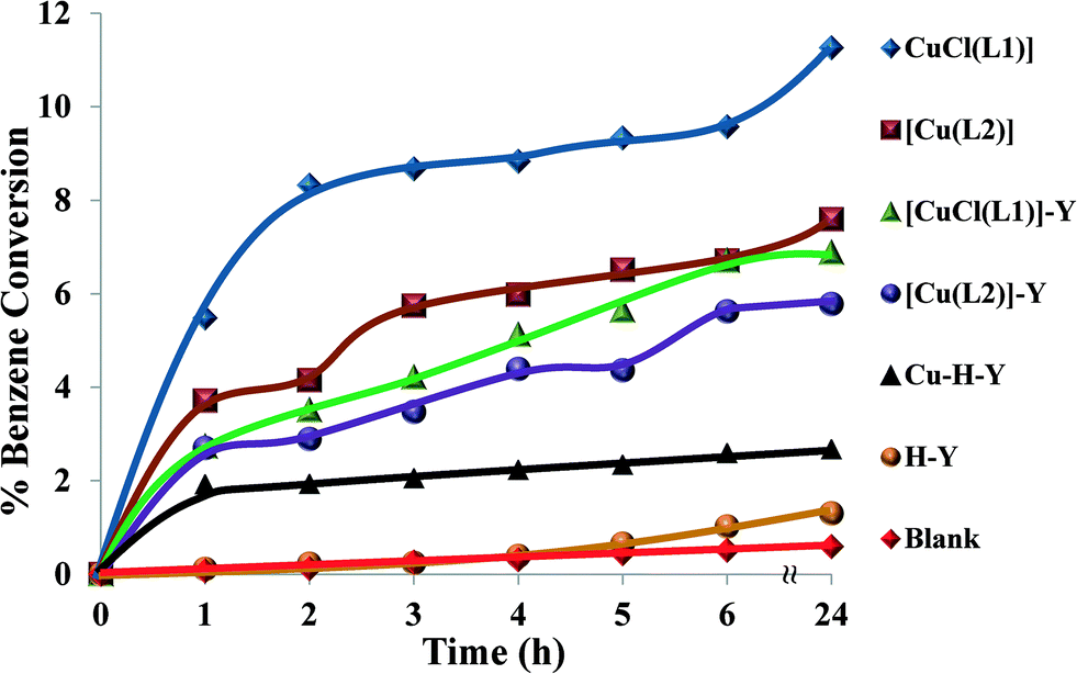 | ||
| Fig. 13 Catalysed hydroxylation of benzene over time. Reaction conditions: benzene (1.93 g), H2O2 (2.83 g), catalyst (0.010 g), CH3CN (3 ml), 70 °C. | ||
The neat complexes [CuCl(L1)] and [Cu(L2)] led to formation of further oxidation products, i.e. CAT and HQ. This is due to the fact that the product (phenol) was more reactive towards oxidation than benzene. It can also be concluded from the table that hydroxylation of benzene, using the encapsulated complexes, was less effective in comparison to their neat analogues. Other possible reasons that could contribute to differences in the reactivity of the encapsulated complexes were steric effects, weak electrostatic interactions and synergism as a result of interactions with the zeolite framework.52
Although neat complexes displayed higher activity than encapsulated catalysts, they showed low benzene conversion. This demonstrated the difficulty of C–H bond activation due to the resonance stability of benzene. Oxidation under Cu-H-Y and H-Y catalysts and blank (without catalyst) yielded negligible conversion.
 | ||
| Scheme 3 Oxidation products of styrene. | ||
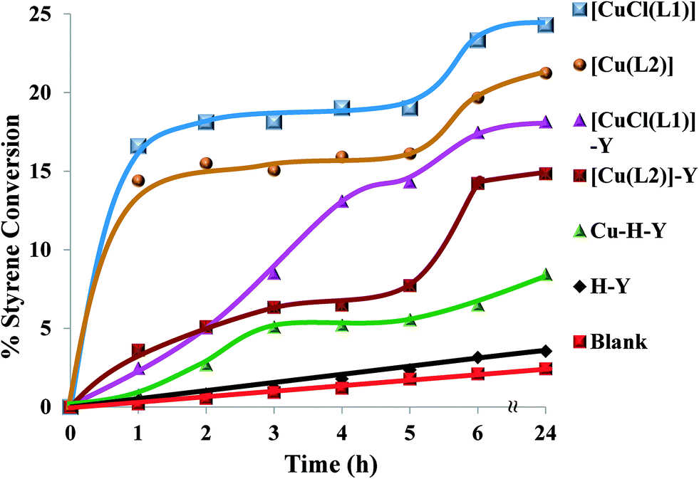
Fig. 14 shows the profiles of conversion percentages of styrene as a function of time for these catalysts. It is clear from Table 5 that the performance of the encapsulated catalysts, [CuCl(L1)]-Y and [Cu(L2)]-Y, was slightly lower than that of their neat analogues.
 | ||
| Fig. 14 Oxidation of styrene over time using various catalysts. Reaction conditions: styrene (2.60 g), H2O2 (2.83 g), catalyst (0.010 g), CH3CN (3 ml), 70 °C. | ||
| Catalysts | % Styrene conversion | % Product selectivity | ||||
|---|---|---|---|---|---|---|
| Bal | Phacetal | Sto | Phediol | Other | ||
| a Reaction conditions: styrene (2.60 g), H2O2 (2.83 g), catalyst (0.010 g), CH3CN (3 ml), 70 °C, 6 h. | ||||||
| [CuCl(L1)] | 23.3 | 70.6 | 6.7 | 7.7 | 7.5 | 7.6 |
| [Cu(L2)] | 19.7 | 72.9 | 4.9 | 8.2 | 7.2 | 7.1 |
| [CuCl(L1)]-Y | 17.5 | 79.8 | 3.7 | 8.5 | 5.6 | 2.5 |
| [Cu(L2)]-Y | 14.2 | 80.6 | 3.6 | 4.2 | 5.0 | 6.6 |
| Cu-H-Y | 6.5 | 73.1 | 4.3 | 2.8 | 4.3 | 15.4 |
| H-Y | 3.2 | 82.8 | 3.0 | 0.6 | 3.3 | 10.3 |
| Blank | 2.1 | 89.7 | 3.1 | 4.0 | 3.6 | 0.4 |
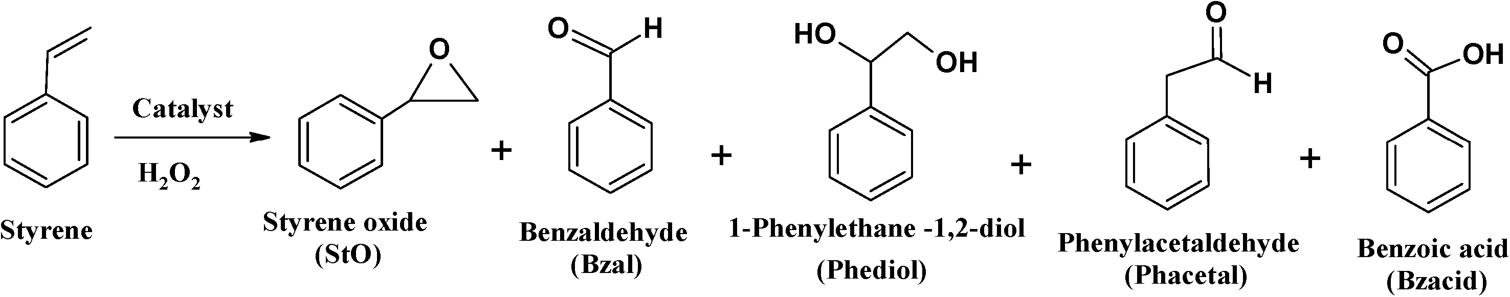
Amongst products formed, benzaldehyde was the major product (71–90%). This is possibly due to the conversion of most of the styrene oxide, which formed in the first step, to benzaldehyde. This occurred via nucleophilic attack of H2O2 on styrene oxide, followed by the cleavage of the intermediate hydroperoxystyrene.53 Formation of benzaldehyde may also occur through direct oxidative cleavage of the styrene side chain double bond via a radical reaction mechanism. The yields of all the other products are in low quantities and comparable. The formation of phenylacetaldehyde is very low for all catalysts and its formation is possibly through isomerization of styrene oxide.
The high amount of water present in H2O2 is partially responsible for the hydrolysis of styrene oxide to form 1-phenylethane-1,2-diol. The other unidentified products could have arisen from further oxidation of benzaldehyde to form other oxidation products. The neat complexes, [CuCl(L1)] and [Cu(L2)], showed a faster conversion of 18–20% in the first 3 h (Fig. 14), whereas the activity of the encapsulated analogues was still very low with <10% conversion. Percentage styrene conversion was improved after 3 h, using the encapsulated catalysts. The lower activity of [CuCl(L1)]-Y and [Cu(L2)]-Y may be understood to have originated from the diffusional resistance faced by styrene molecules in reaching the isolated catalytic centres in the cages of zeolite Y. Therefore, less conversion was expected on going from smaller molecules to substrates having bulkier substituents, making entrance through zeolite pore openings difficult and ultimately resulting in lower activity. From the results presented in Table 5, the percentage styrene conversion follows the order: [CuCl(L1)] > [Cu(L2)] > [CuCl(L1)]-Y > [Cu(L2)]-Y. The selectivity trend of these Cu-catalytic systems was similar in most cases and could be arranged as follows: benzaldehyde ≫ styrene oxide > 1-phenylethane-1,2-diol > phenylacetaldehyde. Cu-H-Y, H-Y and blank were also tested under the same operating conditions but yielded poor activity.
 | ||
| Scheme 4 Oxidation products of cyclohexene. | ||
 | ||
| Fig. 15 Cyclohexene conversion for catalysts over time. Reaction conditions: cyclohexene (2.06 g), H2O2 (2.83 g), catalyst (0.010 g), CH3CN (3 ml), 70 °C. | ||
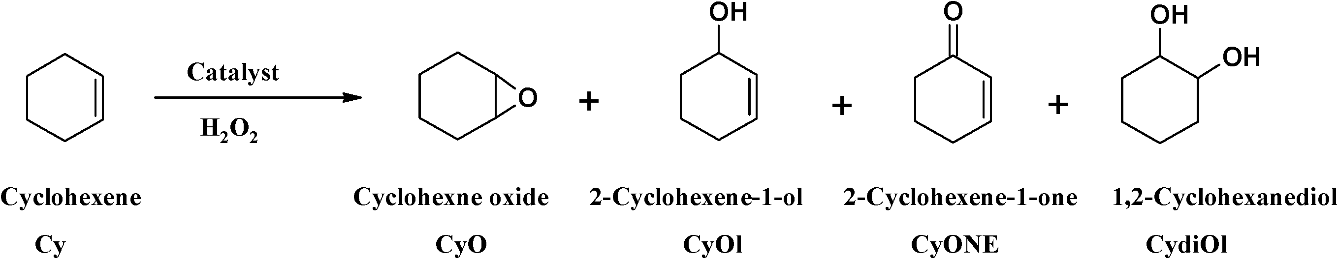
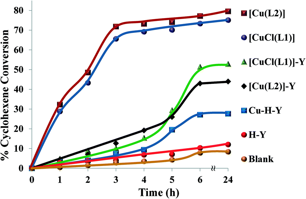
The oxidation of cyclohexene was carried out under optimized reaction conditions. Under these reaction conditions, the encapsulated complexes, [CuCl(L1)]-Y and [Cu(L2)]-Y, gave ~67% and 65% conversion, respectively, after 6 h reaction time. Conversion percentages and product selectivity of the catalysts are listed in Table 6. During the first 4 h, the conversion percentages for [CuCl(L1)]-Y and [Cu(L2)]-Y were very low but gradually increased after longer reaction times. In contrast, neat analogues, [CuCl(L1)] and [Cu(L2)], were more reactive under similar reaction conditions, reaching maximum conversion after 5 h.
| Catalyst | % Cyclohexene conversion | % Product selectivity | ||||
|---|---|---|---|---|---|---|
| CyO | CyOl | CyONE | CydiOl | Other | ||
| a Reaction conditions: cyclohexene (2.06 g), H2O2 (2.83 g), catalyst (0.010 g), CH3CN (3 ml), 70 °C, 6 h. | ||||||
| [CuCl(L1)] | 77.1 | 29.3 | 45.5 | 10.2 | 1.0 | 13.9 |
| [Cu(L2)] | 73.3 | 27.9 | 50.8 | 12.2 | 0.5 | 8.6 |
| [CuCl(L1)]-Y | 51.4 | 32.1 | 28.6 | 19.3 | 13.2 | 6.7 |
| [Cu(L2)]-Y | 43.1 | 43.1 | 30.7 | 18.2 | 4.2 | 3.8 |
| Cu-H-Y | 27.1 | 33.1 | 20.1 | 8.9 | 2.9 | 35.1 |
| H-Y | 10.3 | 39.9 | 12.9 | 16.5 | 6.1 | 24.7 |
| Blank | 7.8 | 33.1 | 20.1 | 8.9 | 2.9 | 35.1 |
In terms of selectivity, the percentage cyclohexene oxide obtained was 29–43%. This may be due to the fact that oxidation reactions occurred mainly on the double bond, giving high yields of cyclohexene oxide. The two allylic products, cyclohexen-1-ol and 2-cyclohexen-1-one, arose from the preferred attack on the activated C–H bond over the C–C bond. It was suggested by Valentine and co-workers54 that the species responsible for cyclohexene oxidation was the product formed from the cleavage of the O–O bond, whereas the epoxide product was formed via direct reaction of olefin with the coordinated HOO− ion. It is also known that the O–O bond in H2O2 is stronger than those in the other oxidants (e.g. THBP) and an HOO− complex is normally expected to have higher activation energy and ultimately have a longer lifetime and higher probability of forming cyclohexene oxide.55,56
The selectivity for the different reaction products for neat copper catalysts followed the order cyclohexen-1-ol > cyclohexene oxide > 2-cyclohexen-1-one > cyclohexan-1,2-diol, while the encapsulated catalysts followed the order cyclohexene oxide > cyclohexen-1-ol > 2-cyclohexen-1-one > cyclohexan-1,2-diol. From the results presented in Table 6, the percentage cyclohexene conversion using these catalysts decreases in the following order: [CuCl(L1)] > [Cu(L2)] > [CuCl(L1)]-Y > [Cu(L2)]-Y.
Cu-H-Y and H-Y under similar reaction conditions exhibit far lower conversion towards oxidation of cyclohexene. It is quite evident that the presence of N and O donor ligands was relevant to improve conversion of cyclohexene. This also substantiated the presence of transition metal complexes at the active site and not the copper ions in zeolite. Therefore, these results suggested that encapsulated and neat Cu(II) complexes catalysed the conversion of cyclohexene, giving high yields of cyclohexene oxide and cyclohexen-1-ol.
2.5 Reusability of the encapsulated catalysts
The reusability of the encapsulated catalyst was examined after recovering the catalyst by filtration and regenerated by Soxhlet extraction using acetonitrile to remove the organic materials remaining on the catalyst's surface. The regenerated catalyst was dried at 120 °C for 6 h and reused three successive times under the same reaction conditions.After two successive cycles, the activity of the catalyst displayed no significant changes in its activity. The catalysts retained optimum activity for phenol hydroxylation for the first two cycles after which a slight drop in activity (ca. 8%) was observed. However, selectivity towards the products remains unaffected. Comparable IR spectral patterns of fresh and regenerated catalysts indicate that the structure remained unchanged. This suggests that these catalysts could be reused after recovery without apparent loss of activity.
Furthermore, ICP analysis indicated no sign of metal leaching into the reaction mixture. Also, no additional conversion was observed after removal of the catalyst from the reaction mixture after 2 h and continuing the reaction for an additional 4 h. This verifies the reaction being catalysed heterogeneously.
3. Experimental
3.1 Materials
The chemicals were used as received without any further purification. Absolute ethanol (99%) was purchased from Saarchem, and copper(II) chloride dihydrate and glacial acetic acid were purchased from Merck. Hydrochloride acid (32%) was purchased from C&L. H-Y zeolite was purchased from Zeolyst. Carbon tetrachloride was purchased from Riedel-de Haen. Dichloromethane (CH2Cl2), phenol (99%), hydrogen peroxide (30%), cyclohexene, ethylenediamine, ethyl acetate, acetonitrile, and acetylacetone were purchased from Sigma Aldrich.3.2 Physical methods and analyses
1H and 13C NMR spectra were recorded in CDCl3 using a Varian XR200 spectrometer (1H at 200 MHz, 13C at 50.3 MHz). Sample signals are relative to the resonance of residual protons in the solvent. Thermal analysis was carried out using a Perkin Elmer TGA Q500 Thermobalance. The nitrogen adsorption/desorption and BET surface area were determined at −196 °C using a Tristar 3000 Micromeritics. All samples were degassed prior to the measurement at 120 °C for 12 h. ATR-IR measurements were carried out using a Perkin-Elmer Spectrum 100 FTIR spectrometer. Raman spectroscopy was carried out using a Dilor XY Raman spectrometer with a Coherent Innova 300 Argon laser with 514.5 nm laser excitation. Electronic spectra were recorded on a GBC UV/VIS 920 UV-Visible spectrophotometer in absolute ethanol or in Nujol (by layering the mull of the sample to the inner side of one of the cuvettes while keeping another one layered with Nujol as a reference) as well as using diffused reflectance under ambient conditions. Scanning electron micrographs (SEM) of the catalysts were recorded on a field-emission scanning electron microscope (Auriga Zeiss SEM) with an accelerating voltage of 5 keV. The samples were coated with Au–Pd for 30 seconds using a Quorum Q150T ES sputter coater to prevent surface changes and to protect the surface material from thermal damage by the electron beam. Powder X-ray diffraction patterns were recorded on a Bruker AXS D8 Advance, High-Resolution diffractometer with Cu Kα radiation (λ = 1.5406 Å) fitted with a PSD Vantec gas detector at iThemba Labs (Cape Town, South Africa). All catalysis reaction products were analyzed using an Agilent 7890 gas chromatograph fitted with a flame ionization detector and an HP-5 phenylmethylsilicone capillary column (30 m × 330 pm × 0.25 μm). The retention time of peaks was compared with authentic samples. Electrochemical studies were carried out using a BAS 100 B electrochemical analyzer. A three-electrode assembly with a Ag/AgCl/KCl (saturated) reference electrode, a Pt wire counter electrode and a glassy carbon (2 mm diameter) working microelectrode was used. All voltammetry investigations were made in acetonitrile solution in the presence of lithium perchlorate as a supporting electrolyte. The percentage metal content was determined using an inductively coupled plasma-optical emission spectrometry (ICP-OES) Varian 710-ES spectrophotometer.3.3 Synthesis
3.3.1.1 Synthesis of 4-(2-amino-ethylimino)-pent-2-en-2-ol Schiff-base ligand (HL1). Schiff-base ligand (HL1) was synthesized using the method described by Styring et al.33 A cold solution of ethylenediamine (0.3 g, 0.005 mol) in dichloromethane (25 mL) was added dropwise to a cold solution of acetylacetone (0.5 g, 0.005 mol) in dichloromethane (25 mL) at 0 °C under continuous stirring. The solution was stirred for 5 min and subsequently heated at reflux for an additional 15 minutes. The solvent was removed under vacuum to obtain a viscous yellow oil. Yield = 0.97 g (68%).
3.3.1.2 Synthesis of (4-[2-(3-hydroxy-1-methyl-but-2-enylideneamino)-ethylimino]-pent-2-en-2-ol Schiff-base ligand (H2L2). H2L2 was synthesized according to the literature procedure.34 A solution of acetylacetone (2.0 g, 0.02 mol) in dichloromethane (25 mL) was added dropwise to a solution of ethylenediamine (0.6 g, 0.01 mol) in dichloromethane (25 mL) under continuous stirring. After addition, the pH of the solution was adjusted to 6 by adding a few drops of glacial acetic acid. The yellow solution was heated at reflux for 4 h at 40 °C. The solvent was removed under vacuum to obtain a yellow solid. It was recrystallized from ethyl acetate
:CH2Cl2 (1:1). The straw yellow crystals were obtained and dried in air. Yield = 2.07 g (55.6%); m.p. = 111–113 °C.
3.3.2.1 Synthesis of the [CuCl(L1)] complex. The complex was synthesized using the method described by Kwiatkowski et al.35 A solution of HL1 (0.714 g, 0.005 mol) in ethanol (25 mL) was added dropwise to a solution of CuCl2·2H2O (0.85 g, 0.005 mol) in ethanol (5 mL) and the mixture was stirred at 30 °C for 2 h. The needle-like complex that separated out of the violet filtrate was collected by filtration and was recrystallized from EtOH
:MeCN (1:3) twice. The violet crystals obtained were dried in air. Yield = 0.35 g (34.3%); m.p. = 162–165 °C.
3.3.2.2 Synthesis of the [Cu(L2)] complex. The method by McCarthy et al.34 was used to prepare [Cu(L2)]. Ligand H2L2 (0.142 g, 0.001 mol) was dissolved in ethanol (10 mL) and a solution of CuCl2·2H2O (0.17 g, 0.001 mol) in ethanol (10 mL) was added dropwise under stirring. The reaction mixture was refluxed for 4 h and was kept overnight. Purple needle-like crystals that separated out were collected by filtration and were washed with cold ethanol. The product was recrystallized from EtOH
:MeCN (1:3) twice and dried at room temperature. Yield = 0.162 g (56.8%); m.p. = 137–139 °C.
3.3.3.1 Preparation of copper(II) exchanged zeolite. Cu-H-Y zeolite was synthesized using a method described elsewhere.36 CuCl2·2H2O (0.34 g, 2.0 mmol) was added to H-Y zeolite (1.0 g) suspended in deionized water (50 mL) and was stirred at 90 °C for 24 h. The resulting suspension was filtered, washed with copious amounts of hot deionized water and then purified by Soxhlet extraction in acetonitrile for 1 h. The residue was collected by filtration and was dried at 150 °C in air for 24 h.
3.3.3.2 Synthesis of zeolite-Y encapsulated copper(II) complexes. Cu-H-Y zeolite (0.3 g) and the ligand (0.7 g) were mixed in MeCN (30 mL), and the reaction mixture was refluxed with stirring for 24 h. The resulting material was collected by filtration and was subsequently Soxhlet extracted in MeCN for 48 h until the extract was free from unreacted ligand. The solid residue was dried at 120 °C in air.
3.4 Catalytic studies
Catalytic liquid-phase oxidation reactions were carried out in a 50 ml round-bottom flask fitted to a water condenser. In a typical reaction, equimolar amounts of substrates (phenol, benzene, styrene and cyclohexene) and 30% H2O2 were mixed in 3 ml of MeCN and the reaction mixture was refluxed and stirred in an oil bath at 70 °C after which the catalyst (0.01 g) to be tested was added and this was assumed to be the starting point of the reaction. The progress of the reaction was monitored as a function of time by withdrawing small aliquots after certain time intervals and analysing them quantitatively using a gas chromatograph.4. Conclusion
In this work, copper(II) complexes of tri- and tetradentate Schiff base ligands were encapsulated in zeolite H-Y super-cages. The structures of the ligands, complexes and corresponding encapsulated complexes were established by various physicochemical techniques. FT-IR and XRD confirmed that the zeolite framework was not affected upon encapsulation of the complex inside the zeolite nano-cage.The activity and selectivity of encapsulated copper(II) catalysts were screened for various oxidation reactions and compared with homogeneous analogues. These catalysts satisfactorily catalyse the hydroxylation of phenol, benzene, styrene and cyclohexene to the desired products, using a green oxidant, H2O2, under moderate reaction conditions.
Homogeneous catalytic systems displayed higher conversion and shorter reaction times in comparison to heterogeneous catalysts. However, the high selectivity and TOF values of the encapsulated catalysts make them more feasible for the industry. Moreover, the heterogeneous catalytic systems can be recovered and reused without loss of catalytic activity. The possible reaction pathway of the catalysts indicates the generation of peroxo-copper intermediate species. These active species are responsible for the transfer of oxygen to the substrates.
References
- P. B. Venuto and P. S. Landis, Adv. Catal., 1968, 18, 259 CAS; J. Čejka and H. Van Bekkum, Zeolites and Ordered Mesoporous Materials: Progress and Prospects (Studies in Surface Science and Catalysis), Elsevier, Amsterdam, 2005, vol. 157 Search PubMed.
- J. C. Jansen, M. Stocker, H. G. Karge and J. Weitkamp, Advanced Zeolite Science and Applications, Elsevier Science, New York, NY, 1994 Search PubMed.
- N. Herron and D. R. Corbin, in Inclusion Chemistry with Zeolites: Nanoscopic Materials by Design, Kluwer Academic Publishers, Dordrecht, The Netherlands, 1995 Search PubMed.
- N. Yan, C. Xiao and Y. Kou, Coord. Chem. Rev., 2010, 254, 1179 CrossRef CAS PubMed.
- I. Kuz'niarska-Biernacka, K. Biernacki, A. L. Magalhães, A. M. Fonseca and I. C. Neves, J. Catal., 2011, 278, 102 CrossRef PubMed.
- F. Zhang, X. Chen, J. Zhuang, Q. Xiao, Y. Zhong and W. Zhu, Catal. Sci. Technol., 2011, 1, 1250 CAS.
- D. Astruc, F. Lu and J. R. Aranzaes, Angew. Chem., Int. Ed., 2005, 44, 7852 CrossRef CAS PubMed.
- Y. Yuan, N. Yan and P. J. Dyson, Inorg. Chem., 2011, 50, 11069 CrossRef CAS PubMed; S. Siankevich, G. Savoglidis, Z. Fei, G. Laurenczy, D. T. L. Alexander, N. Yan and P. J. Dyson, J. Catal., 2014, 315, 67 CrossRef PubMed.
- F. Durap, M. Rakap, M. Aydemir and S. Özkar, Appl. Catal., A, 2010, 382, 339 CrossRef CAS PubMed.
- D. E. De Vos, P. P. Knops-Gerrits, R. F. Parton, B. M. Weckhuysen, P. A. Jacobs and R. A. Schoonheydt, J. Inclusion Phenom. Mol. Recognit. Chem., 1995, 21, 1185 Search PubMed.
- F. Bedioui, Coord. Chem. Rev., 1995, 144, 39 CrossRef CAS.
- B. Romanovsky, Macromol. Symp., 1994, 80, 185 CrossRef CAS PubMed.
- J. Poltowicz, K. Pamin, E. Tabor, J. Haber, A. Adamski and Z. Sojka, Appl. Catal., A, 2006, 299, 235 CrossRef CAS PubMed.
- G. Ertl, H. Knözinger and J. Weitkamp, Preparation of Solid Catalysts, Wiley-VCH Verlag GmbH, Weinheim, 1999 Search PubMed.
- G. J. Hutchings, Chem. Commun., 1999, 301 RSC.
- J. S. Rafelt and J. H. Clark, Catal. Today, 2000, 57, 33 CrossRef CAS.
- R. A. Sheldon, I. W. C. E. Arends and A. Dijksman, Catal. Today, 2000, 57, 157 CrossRef CAS.
- C. Jin, W. Fan, Y. Jia, B. Fan, J. Ma and R. Li, J. Mol. Catal. A: Chem., 2006, 249, 23 CrossRef CAS PubMed.
- M. R. Maurya, S. J. J. Titinchi and S. Chand, J. Mol. Catal. A: Chem., 2004, 214, 257 CrossRef CAS PubMed.
- M. S. Niasari, M. Shaterian, M. R. Ganjali and P. Norouzi, J. Mol. Catal. A: Chem., 2007, 261, 147 CrossRef PubMed.
- K. K. Fodor, G. A. Sebastiaan and R. A. Sheldon, Enantiomer, 1999, 4, 497 CAS.
- V. K. Bansal, P. P. Thankachan and R. Prasad, Appl. Catal., A, 2010, 381, 8 CrossRef CAS PubMed.
- V. K. Bansal, R. Kumar, R. Prasad, S. Prasad and Niraj, J. Mol. Catal. A: Chem., 2008, 284, 1381 CrossRef PubMed.
- H. S. Abbo, S. J. J. Titinchi, R. Prasad and S. Chand, J. Mol. Catal. A: Chem., 2005, 225, 225 CrossRef CAS PubMed.
- H. S. Abbo, S. J. J. Titinchi, S. Chand and R. Prasad, J. Mol. Catal. A: Chem., 2004, 218, 125 CrossRef CAS PubMed.
- N. Herron, Inorg. Chem., 1986, 25, 4714 CrossRef CAS.
- K. J. Balkus Jr., A. A Welch and B. E. Gnade, Zeolites, 1990, 10, 722 CrossRef.
- T. A. Alsalim, J. S. Hadi, E. A. Al-Nasir, H. S. Abbo and S. J. J. Titinchi, Catal. Lett., 2010, 136, 228 CrossRef CAS.
- N. Herron, J. Coord. Chem., 1988b, 19, 25 Search PubMed.
- R. F. Parton, L. Uytterhoeven and P. A. Jacobs, Stud. Surf. Sci. Catal., 1991, 59, 395 CrossRef CAS.
- Introduction to Zeolite Science and Practice (Studies in Surface Science and Catalysis), ed. E. M. Flanigen, J. C. Jansen and H. van Bekkum, Elsevier Science, 1991, vol. 58 Search PubMed.
- Introduction to Zeolite Science and Practice, ed. J. Čejka, H. van Bekkum, A. Corma and F. Schuth, Elsevier, Amsterdam, 2007 Search PubMed.
- P. Styring, C. Grindson and C. M. Fischer, Catal. Lett., 2001, 77, 219 CrossRef CAS.
- P. J. McCarthy, R. J. Hovey, K. Ueno and A. E. Martell, J. Am. Chem. Soc., 1955, 77, 5820 CrossRef CAS.
- M. Kwiatkowski, E. Kwiatkowski, A. Olechnowicz and G. Bandoli, Inorg. Chim. Acta, 1991, 117 CrossRef CAS.
- S. J. J. Titinchi and H. S. Abbo, Top. Catal., 2010, 53, 1401 CrossRef.
- J. P. Costes, Polyhedron, 1987, 6, 2169 CrossRef CAS.
- K. Nakamoto, Infrared and Raman spectra of inorganic and coordination compounds, part I: theory and applications in inorganic chemistry, Wiley, New York, 1997 Search PubMed.
- A. H. Kianfar, L. Keramat, M. Dostani, M. Shamsipur, M. Roushani and F. Nikpour, Spectrochim. Acta, Part A, 2010, 77, 425 CrossRef PubMed.
- H. G. Karge and J. Weitkamp, Molecular Sieves: Science and technology: Characterization I, Springer, 2004, vol. 4, p. 154 Search PubMed.
- P.-P. Knops-Gerrits, D. E. De Vos, E. J. P. Feijen and P. A. Jacobs, Microporous Mesoporous Mater., 1997, 8, 3 CrossRef CAS.
- P. K. Dutta, K. M. Rao and J. Y. Park, J. Phys. Chem., 1991, 95, 6654 CrossRef CAS.
- Y. Suffren, F. R. Rollet and C. Reber, Comments Inorg. Chem., 2011, 32, 246 CrossRef CAS.
- C. R. Jacob, S. P. Varkey and P. Ratnasamy, Microporous Mesoporous Mater., 1998, 22, 469 CrossRef.
- S. P. Varkey, C. Ratnasamy and P. Ratnasamy, J. Mol. Catal. A: Chem., 1998, 135, 301 CrossRef.
- G. Meyer, D. Woehrle, M. Mohl and G. Schulz-Ekloff, Zeolites, 1984, 4, 30 CrossRef CAS.
- S. M. Islama, A. S. Roy, P. Mondal, M. Mubarak, S. Mondal, D. Hossain, S. Banerjee and S. C. Santra, J. Mol. Catal. A: Chem., 2011, 336, 109 Search PubMed.
- B. Sarkar, G. Bocelli, A. Cantoni and A. Ghosh, Polyhedron, 2008, 27, 695 Search PubMed.
- M. R. Maurya, M. Kumar, S. J. J. Titinchi, H. S. Abbo and S. Chand, Catal. Lett., 2003, 86, 103 CrossRef.
- R. Liou, S. Chen, M. Hung, C. Hsu and J. Lai, Chemosphere, 2005, 59, 121 CrossRef PubMed.
- H. S. Abbo and S. J. J. Titinchi, Appl. Catal., A, 2009, 356, 167 CrossRef CAS PubMed.
- T. H. Bennur, D. Srinivas and S. Sivasanker, J. Mol. Catal. A: Chem., 2004, 207, 169 CrossRef.
- M. R. Maurya, U. Kumar and P. Manikandan, Eur. J. Inorg. Chem., 2007, 230 Search PubMed.
- W. Nam, R. Ho and J. S. Valentine, J. Am. Chem. Soc., 1991, 113, 7052 CrossRef CAS.
- P. Chutia, S. Kato, T. Kojima and S. Satokawa, Polyhedron, 2009, 28, 378 CrossRef PubMed.
- J. Y. Lee, R. L. Peterson, K. Ohkubo, I. Garcia-Bosch, R. A. Himes, J. Woertink, C. D. Moore, E. I. Solomon, S. Fukuzumi and K. D. Karlin, J. Am. Chem. Soc., 2014, 136, 9925 CrossRef CAS PubMed.
Footnote |
| † Electronic supplementary information (ESI) available. See DOI: 10.1039/c4cy00915k |
| This journal is © The Royal Society of Chemistry 2015 |