Encapsulating carbon nanotubes with SiO2: a strategy for applying them in polymer nanocomposites with high mechanical strength and electrical insulation†
Received
20th May 2014
, Accepted 25th October 2014
First published on 28th October 2014
Abstract
Multiwalled carbon nanotubes (MWCNTs) have been widely used as mechanical reinforcement fillers for polymers during the past decades. However, the high electrical conductivity of MWCNTs hampers their applications in some specific fields. In this study, the MWCNT was encapsulated with an insulating silicon oxide (SiO2) layer to form core–shell structure MWCNT@SiO2 nanoparticles, which were used to fill bismaleimide-triazine (BT) resin. The obtained polymer nanocomposites possessed high mechanical strength, electrical insulation, improved thermal stability, and good optical transparency. These excellent properties were attributed to the strong interfacial interaction between MWCNT@SiO2 and the polymer, as well as the suppression of electron transport by the SiO2 layer on the MWCNT surface. The nanocomposites were employed to fabricate a printed circuit substrate, on which a frequency “flasher” circuit and the electrical components worked well. This work has demonstrated the possibility of using MWCNTs as mechanical reinforcement fillers in polymer nanocomposites, which simultaneously possess electrical insulation.
1. Introduction
Polymer nanocomposites have received significant attention, both in science and engineering, over recent decades in the development of advanced materials for a wide range of applications.1 Carbon nanotubes (CNTs) have been considered to be ideal reinforcement fillers for high-performance polymer nanocomposites due to their excellent mechanical properties, involving excellent Young's module with values greater than 1 TPa and tensile strength of 63 GPa.2 Addition of a small amount of CNTs to polymers could result in superior mechanical properties, as previously reported.3–6 On the other hand, owing to their intrinsic nature, the addition of CNTs simultaneously leads to enhanced electrical conductivity, even at low volume fractions.7–11 The electrically conductive polymer nanocomposites are regarded as promising materials for use in sensors, actuators, and electromagnetic shielding.12–14 However, high electrical conductivity hampers their application in some fields, such as printed circuit substrates, sealants for semiconductor devices and light emitting diodes.
In order to utilize the outstanding mechanical strength of CNTs while maintaining the electrical insulation of the polymer matrix, an effective solution is to cover the individual CNT with an insulating layer.15–17 For example, Hayashida and coworkers pioneered the design of polymer based CNTs nanocomposites with a high electrical resistance by generating an insulating polymer layer on the surface of the CNTs.18 However, most of the former research19–24 mainly focused on the preparation, and the electrically and thermally conductive properties of the nanocomposites filled with insulated CNTs. The important properties, including mechanical, dielectric, and optical properties, as well as practical applications in printed circuit substrates, have rarely been investigated. The development of the CNTs filled polymer nanocomposites with high mechanical strength, electrical insulation and other excellent properties for practical applications still remains a challenge.
In this study, we developed a strategy for fabricating functionalized MWCNTs filled polymer nanocomposites with high mechanical strength and electrical insulation. The functionalized MWCNTs were prepared by encapsulating MWCNTs with SiO2, and the process was driven by the formation of Si–O–C bonds. Bismaleimide-triazine (BT) resin was employed as a polymer matrix, which has been widely used in printed circuit substrates due to its excellent thermal stability and good retention of mechanical properties at elevated temperatures.25,26 The results indicated that the obtained polymer nanocomposites possessed high mechanical strength, electrical insulation, improved thermal stability, a low dielectric constant of ∼3.5 (1 GHz) and good optical transparency. The nanocomposites have been successfully applied to fabricate a printed circuit substrate, on which a frequency “flasher” worked well. These unique properties were discussed, based on the analysis of the microstructure and interfaces of the prepared nanocomposites.
2. Experimental
2.1 Materials
Tetraethyl orthosilicate (TEOS), ammonia solution (NH4OH) (56 wt%), nitric acid (HNO3), absolute ethanol (CH3CH2OH) and methyl ethyl ketone were acquired from Sinopharm Chemical Reagent Co., Ltd. MWCNTs, prepared by a chemical vapor deposition (CVD) method, were purchased from Carbon Nanotechnology Inc. China. Deionized water was produced by a Milli-Q System (Millipore). 2,2′-Bis(4-cyanatophenyl) propane (BCE, Heijang Kinlyuan Pharmaceutical Co., Ltd., China), 4,4′-bismaleimidodiphenylmethane (BMI, Honghu Bismaleimide Resin Factory, China), and 2,2′diallyl bisphenol A (DBA, Wuxi Resin Factory, China) were used as starting materials to prepare the BT resin, according to our previous work.27 All of the aforementioned reagents were of analytical grade and were used as received.
2.2 Oxidation of MWCNTs
MWCNTs (0.22 g) were modified by treating them in ∼15.0 mol L−1 HNO3 solution (40 mL) under reflux at 120 °C for 6 h. After cooling to room temperature, they were vacuum-filtered through a 0.45 mm polytetrafluoroethylene (PTFE) membrane and washed with deionized water until the filtrate reached a neutral pH. The oxidized MWCNTs were dried under vacuum for 24 h.
2.3 Preparation of MWCNT@SiO2
The preparation of MWCNT@SiO2 was based on MWCNTs–COOH via sol–gel reaction, as reported previously.16 Oxidized MWCNTs (0.20) and ammonia solution (1.0 mL) were sonicated in an ethanol–deionized water mixture (8![[thin space (1/6-em)]](https://www.rsc.org/images/entities/char_2009.gif) :2 v/v, 100 mL) for 1 h. The pH of the mixture was maintained at 11. In parallel, TEOS (2.0 mL) was sonicated in ethanol (40 mL) for 30 min. The TEOS–ethanol mixture was added dropwise to the oxidized MWCNTs solution. The reaction at 30 °C lasted for 2 h after the addition of TEOS. The products were vacuum-filtered through a 0.45 μm PTFE membrane, and washed with absolute ethanol at least 5 times before drying at 80 °C for 12 h.
:2 v/v, 100 mL) for 1 h. The pH of the mixture was maintained at 11. In parallel, TEOS (2.0 mL) was sonicated in ethanol (40 mL) for 30 min. The TEOS–ethanol mixture was added dropwise to the oxidized MWCNTs solution. The reaction at 30 °C lasted for 2 h after the addition of TEOS. The products were vacuum-filtered through a 0.45 μm PTFE membrane, and washed with absolute ethanol at least 5 times before drying at 80 °C for 12 h.
2.4 Preparation of polymer nanocomposites
The polymer nanocomposites were fabricated by solution processing. A certain amount of MWCNT@SiO2 particles dispersed in methyl ethyl ketone were ultrasonicated to form a stable colloid, followed by adding a certain amount of BT resin and stirring for 4 h. Then, a small amount of hardener (2-ethyl-4-methylimidazole) was added, and the mixture was stirred for another 2 h. Finally, the resultant solution mixture was coated onto the copper, and then dried at 100 °C for 2 h to thoroughly evaporate the solvent. The nanocomposites were then cured at 150 °C for 2 h, 180 °C for 2 h, and 200 °C for 2 h in sequence. The thickness of the nanocomposites was about 30 μm. A series of BT/MWCNT@SiO2 nanocomposites were prepared with the MWCNT@SiO2 loading varied between 0.4 and 2.0 wt%. For comparison studies, pure BT resin and nanocomposites filled with pristine MWCNTs and glass fibers were prepared via the same procedure.
2.5 Measurements
The morphology of the MWCNT@SiO2 was examined by transmission electron microscopy (TEM, G2 F20, FEI Tecnai) with an accelerating voltage of 200 kV. The FTIR spectra were obtained on a Bruker Vertex 70 with pure KBr as the background from 400 to 4000 cm−1. UV-vis spectra were performed with a UV-vis spectrometer (UV-3600, Shimadzu). Raman spectra were obtained from 1200 to 3000 cm−1 using a Raman spectrometer (Renishaw inVia Raman microscope, excitation at 514 nm). The chemical state of the surface was characterized by X-ray photoelectron spectroscopy (XPS) on an Axis Ultra-DLD spectrometer (Kratos Analytical Ltd.), using a monochromatized Al Ka source (1486.6 eV) operating at 15 kV and 15 mA. The vacuum during analysis was in the range from 10−10 to 10−9 Pa. The Peakfit software was used to carry out the curve fitting. The volume resistivities of BT/MWCNT@SiO2 and BT/MWCNT nanocomposites were measured using a high-resistance meter (Agilent 4339B, Agilent Technologies) and resistance meter (Keithley 2400, Keithley Instruments), respectively. The dielectric properties were measured with an impedance analyzer (Agilent 4991A) in the frequency range of 107 to 109 Hz. Static uniaxial in-plane tensile tests were conducted with a dynamic mechanical analyzer (DMA Q800, TA Instruments). The samples were cut with a razor into rectangular strips of approximately 4 × 15 mm2 for mechanical testing. All tensile tests were conducted in controlled force rate mode with a preload of 0.001 N and a force ramp rate of 1.0 N min−1. SEM images were obtained using a field-emission scanning electron microscope (Nova NanoSEM 450, FEI) combined with an energy dispersive spectrometer (X-Max50, Oxford Instruments) with 5 or 10 kV accelerating voltage. Thermal stabilities of the nanocomposites were measured via thermogravimetric analysis (TGA, Thermal Analysis (TA) Instruments SDT-Q600 analyzer) in an air environment. The temperature ramps were from 40 to 900 °C at a heating rate of 10 °C min−1. A frequency “flasher” circuit was fabricated by bonding discrete electronic components to the MWCNT@SiO2 nanocomposite film (100 × 50 mm2) to demonstrate its potential application in printed circuit substrates.
3. Results and discussion
3.1 Characterization of MWCNT@SiO2
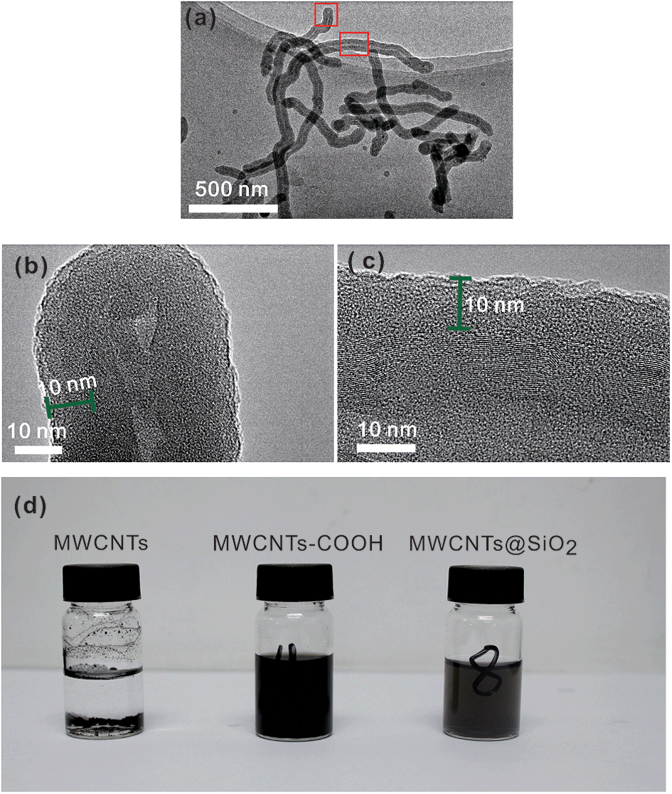
The TEM examination (Fig. 1(a)) reveals that there are almost no free SiO2 particles in the MWCNT@SiO2 fillers. This is attributed to the generation of oxygenated groups on MWCNTs by acid treatment, which facilitates the heterogeneous nucleation of SiO2 on the MWCNT surfaces while inhibiting its homogeneous nucleation. In other words, the oxidization process of MWCNT promotes the formation of SiO2 shell on its surface rather than growth into free SiO2 particles. The amorphous SiO2 layer with a thickness of ∼10 nm is uniformly coated on the surface of MWCNT, as shown in Fig. 1(b) and (c), and SEM images (Fig. S1, ESI†). In addition, the energy dispersive X-ray spectroscopy (EDX) elemental mappings (Fig. S2, ESI†) of carbon, silicon, and oxygen further confirm that SiO2 is uniformly coated onto the MWCNTs. The calculated SiO2 weight loading in MWCNT@SiO2 is 22.8%. Surface functionalization of MWCNT is expected to have a significant effect on its dispersibility in water. In fact, the MWCNT@SiO2 in water exhibits good dispersion, whereas the pristine MWCNTs deposit at the bottom, as shown in Fig. 2(d). Moreover, the MWCNT@SiO2 shows higher light transmittance compared with MWCNTs–COOH with the same loading in water.
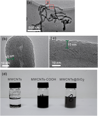 |
| | Fig. 1 TEM images of (a) MWCNT@SiO2; (b) and (c) are the enlarged images of the selected regions in (a) and (d) photograph of pristine MWCNTs, CNTs–COOH and MWCNT@SiO2 dispersed in water. | |
 |
| | Fig. 2 FTIR spectra of pristine MWCNTs, CNTs–COOH, and MWCNT@SiO2. | |
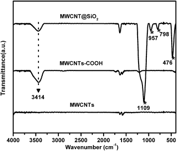
The existence of functional groups in the MWCNT@SiO2 is evidenced by FTIR (Fig. 2). The characteristic absorption bands of MWCNTs@SiO2 at approximately 1109, 957, 798 and 476 cm−1 are ascribed to νas (Si–O–Si), ν(Si–OH), ν(Si–O–Si), and δ(Si–O–Si), respectively, indicating the formation of SiO2 on the MWCNTs. The peak at 3414 cm−1 is assigned to the O–H stretches of Si–OH, which may be beneficial to improve the interfacial interaction of MWCNT@SiO2 with the polymer.
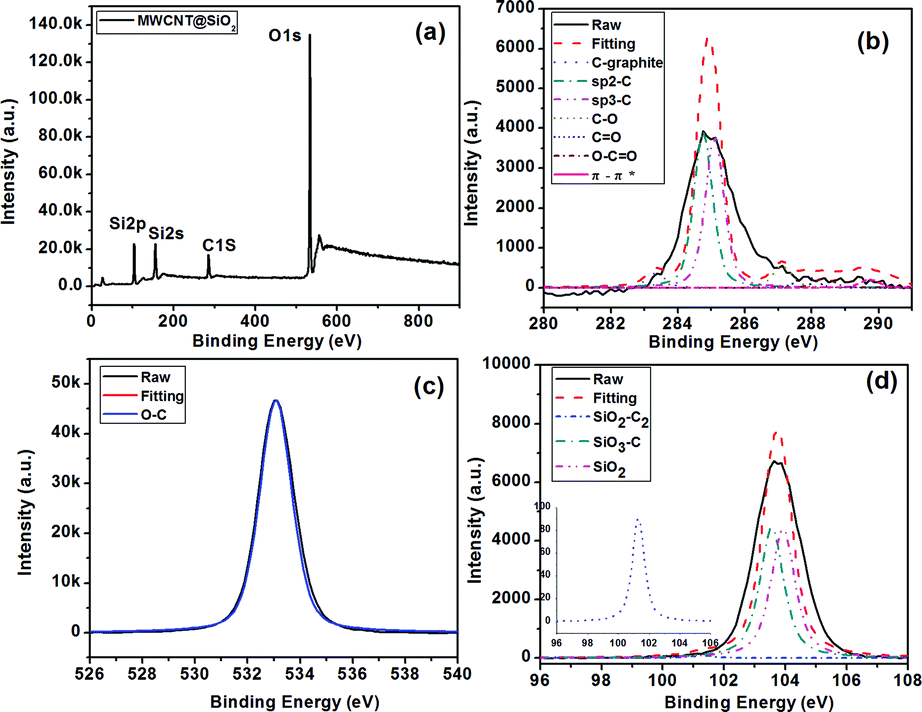
To confirm the formation of a covalent bond between SiO2 and MWCNT, XPS experiments were carried out, as shown in Fig. 3(a). The spectrum of the C1s electron orbital (Fig. 3(b)) indicates the existence of seven carbon components: the graphite (283.3 eV), the Csp2 (284.8 eV), the Csp3 (285.1 eV), the C–O bond (287.1 eV), the C![[double bond, length as m-dash]](https://www.rsc.org/images/entities/char_e001.gif) O bond (287.8 eV), the OC–O bond (289.0 eV), and the carbon of π–π* (289.1 eV). Through the fitting of the O 1s electron orbital spectrum (Fig. 3(c)), the –O– bond (533.0 eV) can be observed. The SiO2 component at 104.2 eV in the Si2p electron orbital spectrum can be observed (Fig. 3(d)). The presence of SiO2–C2 (101.1 eV) and SiO3–C (103.6 eV) bonds indicates the existence of a covalent bond (Si–O–C) between SiO2 and MWCNT.
O bond (287.8 eV), the OC–O bond (289.0 eV), and the carbon of π–π* (289.1 eV). Through the fitting of the O 1s electron orbital spectrum (Fig. 3(c)), the –O– bond (533.0 eV) can be observed. The SiO2 component at 104.2 eV in the Si2p electron orbital spectrum can be observed (Fig. 3(d)). The presence of SiO2–C2 (101.1 eV) and SiO3–C (103.6 eV) bonds indicates the existence of a covalent bond (Si–O–C) between SiO2 and MWCNT.
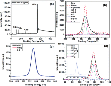 |
| | Fig. 3 XPS spectra of MWCNT@SiO2 (a); high resolution scans of the C1s region (b), O1s region (c), and Si2p region (d) of MWCNT@SiO2. | |
Fig. 4 presents Raman spectra of the MWCNTs@SiO2. The MWCNTs and functionalized MWCNTs (MWCNTs–COOH and MWCNT@SiO2) exhibit a D band at around 1340 cm−1, which is induced by the disordered structure or by the sp3 hybridized carbons, and a G band at around 1570 cm−1, which is derived from the splitting of the E2g stretching mode of graphite. The intensity ratio of the D band and the G band (ID/IG) is used to characterize the defect quantity and monitor the functionalization of carbon materials. In our work, due to increasing defects and new edges introduced during the oxidative treatment, the value of ID/IG increased from 0.83 (pristine MWCNTs) to 0.94 (MWCNTs–COOH). After encapsulating MWCNT with SiO2, the ID/IG of the CNTs decreased to 0.82, even slightly lower than that of the pristine MWCNTs. These results can be interpreted in terms of a slight defect suppression of the lattice after coating with SiO2.
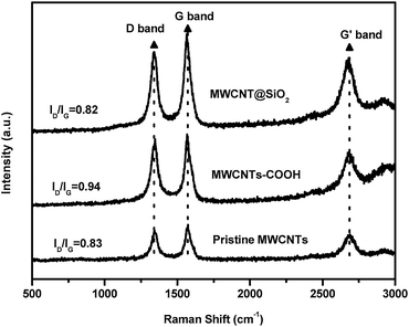 |
| | Fig. 4 Raman spectra of pristine MWCNTs, CNTs–COOH, and MWCNTs@SiO2. | |
3.2 Properties of BT/MWCNT@SiO2 nanocomposites
Optical properties.
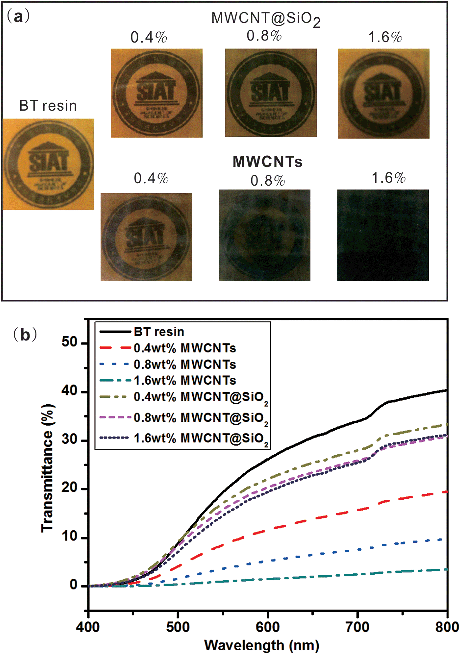
Fig. 5(a) presents images of the BT/MWCNTs@SiO2 and BT/MWCNTs nanocomposite films with different loadings. The BT/MWCNT@SiO2 nanocomposite films are optically transparent at all filler loadings and their light transmittance at 800 nm is about 30%, which is slightly lower than that of the neat BT resin film (37%). In contrast, the light transmittance rate of the BT/MWCNTs nanocomposite films significantly decreases with increasing pristine MWCNTs loadings (Fig. 5(b)). When the pristine MWCNTs loading is 1.6 wt%, the light transmittance of the composite is only 5%. The enhanced optical transmittance compared with pristine MWCNTs should originate from the uniform dispersion of MWCNT@SiO2 in BT resin and the SiO2 layer, which can prevent the light absorption of MWCNTs. The transparent property of materials is very important, especially for applications in flexible displays, colourful e-paper, organic light-emitting diodes (OLEDs) and organic photovoltaics (OPVs). It is assumed that this strategy may be extended to the fabrication of nanocomposites, filled with MWCNT@SiO2, with higher transparency by proper choice of polymers, and thus broaden the application of MWCNT@SiO2.
 |
| | Fig. 5 The effect of MWCNT@SiO2 on the optical transparency and UV-vis transmittance of the nanocomposite films: (a) photographs showing the transparency of samples; (b) UV-vis spectra of nanocomposites with different MWCNT and MWCNT@SiO2 loadings. | |
Electric and dielectric properties.
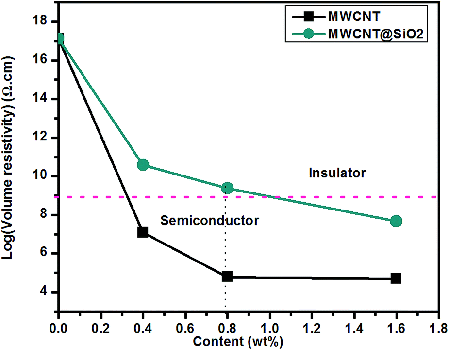
Fig. 6 shows the volume resistivity of the BT/MWCNT@SiO2 and BT/MWCNT nanocomposites with different filler loadings. Addition of a small amount of pristine MWCNTs (0.4 wt%) leads to the transformation of the nanocomposite from insulator to semiconductor. Specifically, the volume resistivity declines from 1.32 × 10¹⁷ Ω cm, for pure BT resins, to 6.14 × 10⁴ Ω cm for the nanocomposite containing 0.8 wt% MWCNTs. In contrast, the insulating SiO2 coated on the MWCNT surface exhibits a barrier effect on the electrons transformation. The volume resistivity of the nanocomposites containing MWCNT@SiO2 is higher by approximately five orders of magnitude than that of those containing the pristine MWCNTs, at the same loading. When the MWCNT@SiO2 loading is 0.8 wt%, the measured volume resistivity of the nanocomposite is 2.36 × 10⁹ Ω cm, indicating that it is still an insulator (>1.0 × 10⁹ Ω cm). However, further increase of MWCNT@SiO2 loading leads to a decrease in volume resistivity to 4.74 × 10⁷ Ω cm, suggesting that the nanocomposite is not insulated.
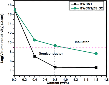 |
| | Fig. 6 Volume resistivity of BT/MWCNT and BT/MWCNT@SiO2 nanocomposites with different filler loadings. | |
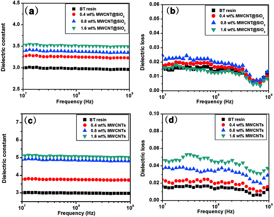
The miniaturization of electronic devices integrated in printed circuits substrates has resulted in the rapid increase of the propagation delay caused by interconnection. In order to reduce the resistance–capacitance (RC) delay, low dielectric constant and loss of insulating materials are urgently desired.28 As shown in Fig. 7(a) and (b), all nanocomposites show similar dielectric stability on frequency, and their dielectric constants increase linearly with the loading amount. Compared to the pristine MWCNTs (Fig. 7(c)), MWCNT@SiO2 leads to less improvement in the dielectric constant of BT resin. With the same loading (1.6 wt%), the dielectric constant of BT/MWCNT@SiO2 nanocomposites increases from 3.0 for pure BT resin to 3.5, while it increases to 5.0 for BT/MWCNTs nanocomposites. On the other hand, it seems that the addition of MWCN@SiO2 does not influence the dielectric loss of BT resin. In contrast, the dielectric loss of the BT/MWCNTs nanocomposites (Fig. 7(d)) increases with filler loading and reaches up to 0.04. We also found that adding more MWCNT@SiO2 (2.0 wt%) leads to increased dielectric loss (0.04) (Fig. S3, ESI†), which may be attributed to the poorer dispersion of MWCNT@SiO2 in BT resins, which causes the regional formation of a conductive network of CNT within the polymer matrix. There are two possible explanations for the discrepancy of dielectric properties between MWCNT@SiO2 and MWCNT. First, the insulated SiO2 layer on MWCNT limits the dipole moment, resulting in low energy storage in an electromagnetic field. Second, dielectric properties depend on the interaction between inorganic and the polymer. Because MWCNT@SiO2 has a stronger interaction with BT resin than pure MWCNTs due to the existence of an active –OH group, MWCNT@SiO2 fillers have a greater restricting influence on the orientation and relaxation of dipoles than MWCNTs in nanocomposites.
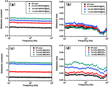 |
| | Fig. 7 Dielectric constant and loss of BT/MWCNT@SiO2 (a and b) and BT/MWCNT (c and d) with different filler loadings. | |
Mechanical properties.
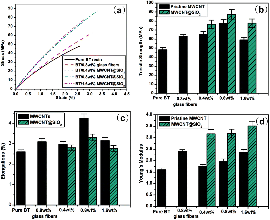
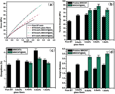
Fig. 8(a) shows the typical stress–strain curves of BT/MWCNT@SiO2 nanocomposites. The stress strength (Fig. 8(b)) and ultimate strain (Fig. 8(c)) were extracted from the curve just before failure. The Young's modulus (Fig. 8(d)) was calculated from the slope of the linear fit in the initial section of the curve (0.5% strain). For the neat BT resin film, the stress strength, elongation and Young's modulus are 48.2 MPa, 2.6% and 1.6 GPa, respectively. After the addition of pristine MWCNTs or MWCNT@SiO2, the mechanical properties of BT resin increase with the filler loadings, and the addition of 0.8 wt% fillers exhibits the highest stress strength and elongation. Adding more fillers brings about a slight decrease in the stress strength and elongation. Such a phenomenon was also observed in other reports.29,30 This could be due to the regional agglomeration of the filler particles in the composite, which limits the efficiency of reinforcement. As compared to the pristine MWCNTs, MWCNT@SiO2 leads to more pronounced improvement in the mechanical properties, except for the elongation values. The stress strength and Young's modulus of the nanocomposite containing 0.8 wt% MWCNT@SiO2 are 87.4 MPa and 3.18 GPa, respectively, which are higher than those of the BT/pristine MWCNTs. Fig. 8(d) displays that the elongation values of BT/MWCNT@SiO2 are lower than those of the BT/MWCNTs composites, but still higher than that of pure BT resin. The results indicate strong interfacial interaction between MWCNT@SiO2 and BT resin, which leads to difficult deformation of the nanocomposites under the tensile loading. Furthermore, as a control experiment, we also measured the mechanical properties of the composite filled with 0.8 wt% glass fibers, which are the conventional composites used as printed circuit substrate materials. As shown in Fig. 8, the tensile strength, elongation and Young's modulus are 63.0 MPa, 2.4 GPa, and 3.1%, respectively, which are all lower than those of the nanocomposite filled with 0.8 wt% MWCNT@SiO2. The control experiments with pristine MWCNTs and glass fibers confirm that MWCNT@SiO2 plays a key role for the enhancement of the mechanical properties of BT resins.
 |
| | Fig. 8 (a) Typical stress–strain curves of BT resin based nanocomposites with different loadings of MWCNT@SiO2 or MWCNTs, (b) absolute value of tensile strength, (c) percentage elongation, and (d) Young's modulus of the nanocomposites. | |
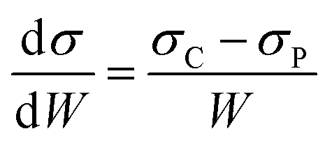
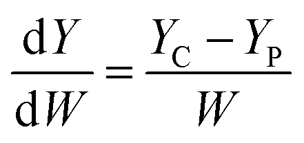
In order to compare the mechanical properties of the nanocomposites filled with functionalized CNTs, we define the rate of increase of tensile strength (σ) and Young's modulus (Y) to the weight fraction (W) of the CNTs. The equations are as follows:
| |  | (1) |
| |  | (2) |
Table 1 summarizes recent typical studies on the effects of functionalized CNTs on the mechanical properties of polymer nanocomposites. These results indicate that the addition of functionalized CNTs can enhance the tensile strength and Young's modulus, and different systems possess different degrees of mechanical improvement. In our research, the dσ/dW and dY/dW are as high as 4900 and 200, respectively, which are higher than most reported values. Therefore, we believe that the improvement of 81.2% and 98.5% in both tensile strength and Young's modulus in our results is significant.
Table 1 Comparison of the mechanical properties of polymer nanocomposites between our BT/MWCNT@SiO2 nanocomposite and the data from literature
| Systema |
CNTs loading |
dσ (MPa) |
dY (GPa) |
dσ/dW |
dY/dW |
Reference and year |
|
PMMA: Poly(methyl methacrylate); f-SWNTs: functionalized single-walled carbon nanotubes; f-MWCNTs: functionalized multi-walled carbon nanotubes.
|
| BT/MWCNT@ SiO2 (this study) |
0.8 wt% |
39.2 |
1.6 |
4900 |
200 |
— |
| PMMA/f-MWCNTs |
0.5 wt% |
20.6 |
1.2 |
4120 |
240 |
29 and 2012 |
| Epoxy/f-SWNTs |
0.5 wt% |
34.4 |
0.5 |
6880 |
100 |
31 and 2011 |
| Epoxy/f-SWNTs |
4.0 wt% |
19 |
1.4 |
475 |
35 |
32 and 2004 |
| Epoxy/f-SWNTs |
1.0 wt% |
10.6 |
0.7 |
1060 |
73 |
33 and 2008 |
| Epoxy/f-MWNTs |
5.0 wt% |
Negligible |
0.6 |
— |
12 |
34 and 1998 |
| Epoxy/f-MWCNTs |
6.0 wt% |
Decrease |
1.38 |
Decrease |
23 |
35 and 2004 |
| Epoxy/f-MWCNTs |
1.0 wt% |
11 |
1.2 |
1100 |
120 |
36 and 2003 |
| Epoxy/f-MWCNTs |
0.25 wt% |
20 |
0.6 |
8000 |
240 |
37 and 2008 |
| Vulcanized rubber/f-SWCNTs |
∼1.0 wt% |
4.5 |
0.46 |
450 |
46 |
38 and 2007 |
| Polyurethane/f-SWCNTs |
0.7 wt% |
7 |
14.2 |
1000 |
2028 |
39 and 2006 |
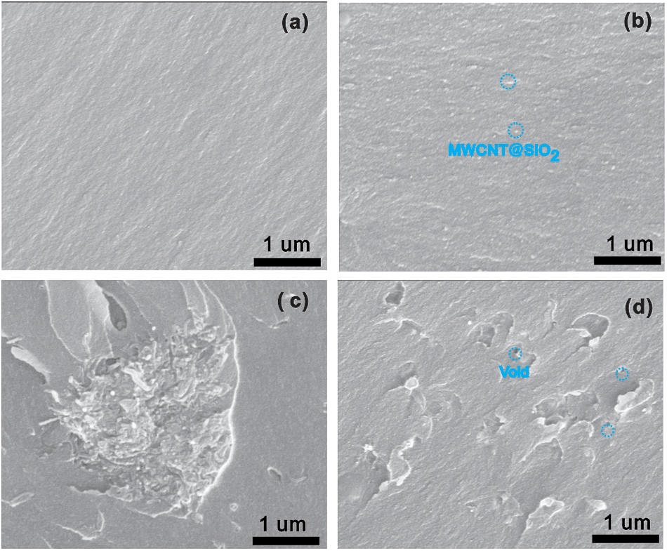
As is known, the mechanical reinforcement of MWCNT filled nanocomposites strongly depends on the extent of load transfer between the matrix and MWCNTs.31,40,41 For MWCNT@SiO2, a number of OH groups have been verified to be attached to its surface, while pristine MWCNTs lack surface functional groups, as indicated in Fig. 2. Therefore, the MWCNT@SiO2 has stronger interfacial interactions with BT resins than pristine MWCNTs. These innate advantage results in efficient stress transfer between the MWCNT@SiO2 and BT matrix, which could avoid the deformation or fracture of the materials under external force. On the other hand, the dispersion of nanofiller in the matrix is another key factor that affects the reinforcement. As shown in SEM images in Fig. 9(a), the pure BT resin exhibits a smooth fracture surface. After the addition of MWCNT@SiO2 (0.8 wt%) into the BT resin, MWCNT@SiO2 are well-dispersed in the nanocomposites, as shown in Fig. 9(b). In contrast, the agglomeration or voids can be clearly seen in the BT/MWCNTs nanocomposite with the same nanofiller loading (Fig. 9(c)). Owing to the good dispersion of MWCNT@SiO2 in the matrix, the large surface area enables more interaction sites at the polymer/nanofiller interphase, leading to the improved mechanical strength. With a higher loading of 1.6 wt%, the composite exhibits a significantly increased viscosity, such that porosity is easily introduced to the composite, as shown in Fig. 9(d). The tensile strength of composites is very sensitive to such void defects. Therefore, a slightly decreased tensile strength is observed for the composite with the addition of 1.6 wt% MWCNT@SiO2.
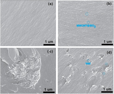 |
| | Fig. 9 SEM fractographs of the pure BT resin and BT/MWCNTs@SiO2 nanocomposites: (a) the pure BT resin; (b) 0.8 wt% MWCNT@SiO2; (c) 0.8 wt% pristine MWCNTs and (d) 1.6 wt% MWCNT@SiO2. | |
Thermal stability.
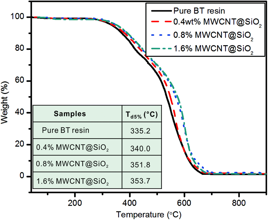
Thermal stability is one of the most important properties of the nanocomposites to assess their processing and service-life performance in the applications of printed circuit substrates. Fig. 10 shows the TGA curves for the pure BT resin and BT/MWCNT@SiO2 nanocomposites. The nanocomposites are stable up to 350 °C, and then completely decompose at above 700 °C, leaving no residue. The 5 wt% weight loss temperatures (Td5%) for all samples are extracted and summarized in the inset of Fig. 10. The values of Td5% increase from 335.2 °C for the pure BT resin to 353.7 °C for the nanocomposite containing 1.6 wt% MWCNT@SiO2, indicating the improved thermal stability. The stabilization effect of MWCNTs@SiO2 is mainly attributed to good polymer matrix-MWCNT@SiO2 interaction, as well as the barrier effect of MWCNT@SiO2. Furthermore, the growth of Td5% slows down, when the MWCNT@SiO2 content is more than 0.8 wt% due to the existence of agglomerations in the composite, as shown in the SEM image (Fig. 9(d)).
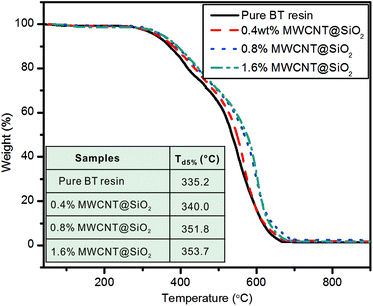 |
| | Fig. 10 TGA curves of the pure BT resin and nanocomposites containing different MWCNT@SiO2 loadings. The inset shows the Td5% values for all samples. | |
4. Application in frequency “flasher” circuit
In order to demonstrate the potential application of the BT/MWCNT@SiO2 nanocomposites in printed circuit substrates, we fabricated a frequency “flasher” circuit by bonding discrete electronic components to our nanocomposite substrate. The MWCNT@SiO2 loading in the nanocomposite is 0.8 wt%, which leads to the maximum values in mechanical properties, as shown in the abovementioned results. It should be noted that the BT loaded with 0.8 wt% pristine MWCNTs cannot be used as the printed circuit substrate, because of its low electrical resistivity. In addition, the pure BT resin is also not the ideal circuit substrate because of its low mechanical strength, which will lead to easy breakage during the fabrication of the circuit.
Fig. 11(a) presents the circuit principle diagram. The circuit comprises of four resistors (R1, R2, R3, and R4), one capacitor, one power source (6 V), one 555 timer integrated circuit (NE555) and two LEDs (green (D1) and red (D2)). The detailed manufacturing process of the frequency “flasher” circuits follows that of the common printed circuit boards (PCB). A copper (Cu) clad laminate containing MWCNT@SiO2 was prepared in order to use copper wire as the electrical circuit. Fig. S4† shows the fabrication process of the copper clad laminate. The electrical circuit was fabricated by UV photoengraving method (Fig. S5, ESI†). The circuit could be turned on by connecting the negative and positive electrodes (Fig. 11(b)). The working printed circuit substrate demonstrates excellent flexibility. As shown in Fig. 11(c), it functioned well after bending to a certain extent. When the circuit is on, the two LEDs flash alternately at a fixed frequency (Fig. 11(d)). A movie of the operation of the LED chip can be found in the ESI (see Movie S1, ESI†).
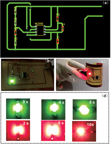 |
| | Fig. 11 Applications of the nanocomposite in printed circuit substrates: (a) circuit principle diagram of FFC; (b and c) optical images of FFC working before and after bending; (d) optical images of two LEDs flashed alternately. | |
5. Conclusions
We have demonstrated a strategy for fabricating MWCNTs based polymer nanocomposites with high mechanical strength and electrical insulation by encapsulating MWCNT with SiO2 (MWCNT@SiO2). With only 0.8 wt% MWCNT@SiO2, the resultant nanocomposites exhibit 81.2% and 98.5% increases in tensile strength and Young's modulus (compared to pure BT resin), respectively. The volume resistivity of the nanocomposites containing MWCNT@SiO2 is higher by approximately five orders of magnitude than that of nanocomposites containing the pristine MWCNTs at the same loadings. The addition of MWCNT@SiO2 hardly affects the dielectric properties and optical transparency of BT resin. Furthermore, the values of Td5% increase with the increase of MWCNT@SiO2, and reach 353.7 °C for the nanocomposite containing 1.6 wt% MWCNT@SiO2, which is 18.5 °C higher than that of pure BT resin. These excellent properties are attributed to the strong interfacial interactions of MWCNT@SiO2 with BT resin and high electrical insulation of the SiO2-coated MWCNTs. The BT/MWCNT@SiO2 nanocomposites have been successfully demonstrated as a printed circuit substrate, on which a frequency “flasher” circuit and the electrical components worked well. The concept of using MWCNT@SiO2 as fillers in this study will also be applicable to a wide range of other polymer nanocomposites.
Acknowledgements
The authors acknowledge the financial support from National Natural Science Foundation of China (no. 51377157), Guangdong and Shenzhen Innovative Research Team Program (no. 2011D052 and KYPT20121228160843692) and Shenzhen Electronic Packaging Materials Engineering Laboratory (no.2012-372).
Notes and references
- M. Naffakh, A. M. Díez-Pascual, C. Marco, G. J. Ellis and M. A. Gómez-Fatou, Prog. Polym. Sci., 2013, 38, 1163–1231 CrossRef CAS PubMed.
- J. N. Coleman, U. Khan and Y. K. Gun'ko, Adv. Mater., 2006, 18, 689–706 CrossRef CAS.
- N. Roy, R. Sengupta and A. K. Bhowmick, Prog. Polym. Sci., 2012, 37, 781–819 CrossRef CAS PubMed.
- A. M. Diez-Pascual and D. Gascon, ACS Appl. Mater. Interfaces, 2013, 5, 12107–12119 CAS.
- Y. Ma, P. L. Chiu, A. Serrano, S. R. Ali, A. M. Chen and H. He, J. Am. Chem. Soc., 2008, 130, 7921–7928 CrossRef CAS PubMed.
- N. G. Sahoo, S. Rana, J. W. Cho, L. Li and S. H. Chan, Prog. Polym. Sci., 2010, 35, 837–867 CrossRef CAS PubMed.
- C. Min, X. Shen, Z. Shi, L. Chen and Z. Xu, Polym.-Plast. Technol. Eng., 2010, 49, 1172–1181 CrossRef CAS.
- T. Souier, C. Maragliano, M. Stefancich and M. Chiesa, Carbon, 2013, 64, 150–157 CrossRef CAS PubMed.
- J. Zhang, D. Jiang, H.-X. Peng and F. Qin, Carbon, 2013, 63, 125–132 CrossRef CAS PubMed.
- E. Y. Li and N. Marzari, ACS Nano, 2011, 5, 9726–9736 CrossRef CAS PubMed.
- S. L. Zhang, S. B. Yin, C. R. Rong, P. F. Huo, Z. H. Jiang and G. B. Wang, Eur. Polym. J., 2013, 49, 3125–3134 CrossRef CAS PubMed.
- X. Sun, H. Sun, H. Li and H. Peng, Adv. Mater., 2013, 25, 5153–5176 CrossRef CAS PubMed.
- S. Desbief, N. Hergue, O. Douheret, M. Surin, P. Dubois, Y. Geerts, R. Lazzaroni and P. Leclere, Nanoscale, 2012, 4, 2705–2712 RSC.
- Y. Q. Li, Y. A. Samad, K. Polychronopoulou, S. M. Alhassan and K. Liao, Sci. Rep., 2014, 4, 4652 Search PubMed.
- K. Ding, B. Hu, Y. Xie, G. An, R. Tao, H. Zhang and Z. Liu, J. Mater. Chem., 2009, 19, 3725–3731 RSC.
- A. J. Paula, D. Stefani, A. G. Souza Filho, Y. A. Kim, M. Endo and O. L. Alves, Chem.–Eur. J., 2011, 17, 3228–3237 CrossRef CAS PubMed.
- S. W. Kim, T. Kim, Y. S. Kim, H. S. Choi, H. J. Lim, S. J. Yang and C. R. Park, Carbon, 2012, 50, 3–33 CrossRef CAS PubMed.
- K. Hayashida and H. Tanaka, Adv. Funct. Mater., 2012, 22, 2338–2344 CrossRef CAS.
- S. K. Yadav, I. J. Kim, H. J. Kim, J. Kim, S. M. Hong and C. M. Koo, J. Mater. Chem. C, 2013, 1, 5463–5470 RSC.
- T. Morishita, M. Matsushita, Y. Katagiri and K. Fukumori, J. Mater. Chem., 2011, 21, 5610–5614 RSC.
- W. Cui, F. Du, J. Zhao, W. Zhang, Y. Yang, X. Xie and Y.-W. Mai, Carbon, 2011, 49, 495–500 CrossRef CAS PubMed.
- Y. Zhang, S. Xiao, Q. Wang, S. Liu, Z. Qiao, Z. Chi, J. Xu and J. Economy, J. Mater. Chem., 2011, 21, 14563–14568 RSC.
- J. Di, Z. Yong, Z. Yao, X. Liu, X. Shen, B. Sun, Z. Zhao, H. He and Q. Li, Small, 2013, 9, 148–155 CrossRef CAS PubMed.
- A. Gohier, B. Laik, K.-H. Kim, J.-L. Maurice, J.-P. Pereira-Ramos, C. S. Cojocaru and V. Pierre Tran, Adv. Mater., 2012, 24, 2592–2597 CrossRef CAS PubMed.
- X. Zeng, S. Yu and R. Sun, J. Appl. Polym. Sci., 2013, 128, 1353–1359 CAS.
- X. Zeng, S. Yu, R. Sun and R. Du, Mater. Chem. Phys., 2011, 131, 387–392 CrossRef CAS PubMed.
- X. L. Zeng, S. H. Yu and R. Sun, J. Appl. Polym. Sci., 2013, 128, 1353–1359 CAS.
- C. Yuan, K. Jin, K. Li, S. Diao, J. Tong and Q. Fang, Adv. Mater., 2013, 25, 4875–4878 CrossRef CAS PubMed.
- J. Wang, Z. Shi, Y. Ge, Y. Wang, J. Fan and J. Yin, J. Mater. Chem., 2012, 22, 17663–17670 RSC.
- L. An, Y. Pan, X. Shen, H. Lu and Y. Yang, J. Mater. Chem., 2008, 18, 4928–4941 RSC.
- J. M. Gonzalez-Dominguez, A. Anson-Casaos, A. M. Diez-Pascual, B. Ashrafi, M. Naffakh, D. Backman, H. Stadler, A. Johnston, M. Gomez and M. Teresa Martinez, ACS Appl. Mater. Interfaces, 2011, 3, 1441–1450 CAS.
- J. Zhu, H. Peng, F. Rodriguez-Macias, J. L. Margrave, V. N. Khabashesku, A. M. Imam, K. Lozano and E. V. Barrera, Adv. Funct. Mater., 2004, 14, 643–648 CrossRef CAS.
- L. Sun, G. L. Warren, J. Y. O'Reilly, W. N. Everett, S. M. Lee, D. Davis, D. Lagoudas and H. J. Sue, Carbon, 2008, 46, 320–328 CrossRef CAS PubMed.
- L. S. Schadler, S. C. Giannaris and P. M. Ajayan, Appl. Phys. Lett., 1998, 73, 3842–3844 CrossRef CAS PubMed.
- Y. Breton, G. Désarmot, J. P. Salvetat, S. Delpeux, C. Sinturel, F. Béguin and S. Bonnamy, Carbon, 2004, 42, 1027–1030 CrossRef CAS PubMed.
- J. Bai, Carbon, 2003, 41, 1325–1328 CrossRef CAS.
- Y. Geng, M. Y. Liu, J. Li, X. M. Shi and J. K. Kim, Composites, Part A, 2008, 39, 1876–1883 CrossRef PubMed.
- A. M. Shanmugharaj, J. H. Bae, K. Y. Lee, W. H. Noh, S. H. Lee and S. H. Ryu, Compos. Sci. Technol., 2007, 67, 1813–1822 CrossRef CAS PubMed.
- H. Xia and M. Song, J. Mater. Chem., 2006, 16, 1843–1851 RSC.
- Z. Chen and H. Lu, J. Mater. Chem., 2012, 22, 12479–12490 RSC.
- D. Ciprari, K. Jacob and R. Tannenbaum, Macromolecules, 2006, 39, 6565–6573 CrossRef CAS.
Footnote |
| † Electronic supplementary information (ESI) available: SEM images of MWCNT@SiO2, EDX elemental mapping of MWCNT@SiO2, dielectric properties of BT/2.0 wt% MWCNT@SiO2 nanocomposite, preparation of copper clad laminate containing MWCNT@SiO2, fabrication of electrical circuit by subtractive process, and a video that shows the operation of the frequency “flasher” circuits. See DOI: 10.1039/c4tc01051e |
|
| This journal is © The Royal Society of Chemistry 2015 |
Click here to see how this site uses Cookies. View our privacy policy here.