Efficient oxygen electroreduction over ordered mesoporous Co–N-doped carbon derived from cobalt porphyrin†
C. Li,
Z. Han,
Y. Yu,
Y. Zhang,
B. Dong,
A. Kong* and
Y. Shan*
School of Chemistry and Molecular Engineering, East China Normal University, 500 Dongchuan Road, Shanghai 200241, P. R. China. E-mail: ykshan@chem.ecnu.edu.cn; agkong@chem.ecnu.edu.cn
First published on 29th January 2016
Abstract
The demand for directly converting chemical energy generated by exothermal redox reactions into electrical energy has increased markedly in recent years and motivates the development of novel electrochemical power sources. The use of fuel cell technology may be the most promising solution for electrochemical propulsion in electric vehicles. However, at present, the design and synthesis of high-performance and low-cost catalysts for the oxygen reduction reaction (ORR) still remains a significant challenge. Here, a high-performance Co-based carbon electrocatalyst (Co–N–GC) for the ORR is prepared by a simple wet-impregnation nanocasting method using SBA-15 as a hard template and water-soluble cobalt porphyrin as a precursor. The prepared catalysts with Co–Nx moieties have ordered mesoporous channels, and high specific surface area and degree of graphitization. In 0.1 M HClO4 medium, the ORR over Co–N–GC prepared at the optimized heat-treatment temperature (800 °C) exhibits a positive half-wave potential (0.79 V) and higher ORR current density (5.6 mA cm−2 at 0.2 V) compared to commercial Pt/C (20 wt%) catalysts. Moreover, the prepared Co–N–GC materials possess intrinsic long-time stability and the excellent methanol resistance toward the ORR in both acidic and alkaline media, and may serve as a promising alternative to Pt/C materials for the ORR in the widespread implementation of fuel cells.
1. Introduction
Using nonprecious metal catalysts (NPMCs) for the oxygen reduction reaction on the cathode of polymer electrolyte fuel cells (PEFCs) is more economical, and has important significance to the widespread implementation of PEFCs in clean energy applications.1 Extensive efforts have been made to explore the construction of NPMCs with the desired performance. A large number of efficient NPMCs with desired morphology and architecture have been investigated in the past decades.2–5 Among numerous NPMCs reported,6–16 carbon-supported iron–nitrogen (Fe–N/C) and cobalt–nitrogen catalysts (Co–N/C) are believed to be the most promising alternatives to the platinum-based catalysts, due to their excellent electrocatalytic performance towards the oxygen reduction reaction (ORR).17–20 However, from a practical point of view, in harnessing the chemical energy via direct electrochemical conversion, their electrocatalytic activity and stability are still insufficient and need to be further improved.Some experimental investigation results illustrated that iron-based catalysts showed higher ORR activity than Co-based catalysts, but the latter usually exhibited higher catalytic stability.21 Improving the catalytic activity of Co–N/C materials or increasing catalytic stability of Fe–N/C materials should be an effective way to develop highly efficient NPMCs that can gain satisfied result in practical use. Along this direction, the Fe–N/C electrocatalysts with high ORR performance were widely prepared by optimizing the synthesis parameters including species of precursors, heat-treatment temperatures, and carbon supports etc. However, there is only a limited progress on the activity enhancement of Co-based electrocatalysts. By choosing different nitrogen-containing organic compounds, for example, porphyrins, phthalocyanines, dibenzotetraazaannulenes, phenanthrolines, polypyrrole, triethylenetetramine chelate and tripyridyl triazine and optimizing the synthesis conditions such as the mole ratio of N to Co atoms, heat-treatment procedures and carbon supports, some synthesis routes were also explored for the preparation of high-performance Co-based NPMCs.22–29 Among them, ORR half-potential of the best Co-based catalyst is about 10 mV lower than that of commercial Pt/C catalyst in alkaline medium and about 40 mV in acidic medium. It is still a challenge to prepare Co-based NPMCs with high ORR performance comparable to commercial Pt/C catalysts over a wide pH range of aqueous media.
Cobalt porphyrins with Co–N4 moieties were widely used as the effective precursors for the preparation of Co and N co-doped carbon.30–36 However, most of Co–N–C materials are prepared by the pyrolysis of carbon-supported cobalt porphyrin. The limited loading content for maintaining their well-dispersion on carbon supports and the stripping and aggregation phenomenon of active Co–nitrogen–carbon species and carbon supports often undermined the catalytic activity and stability of such Co–N–C materials. Recently, carbon-supported Co–N–C materials were prepared by thermally conversion of Co–porphyrin and believed to be highly efficient electrocatalyst for ORR, but which are well below the performance of the commercial Pt/C catalyst.34–36
Herein, a self-supported Co–N-doped mesoporous graphite catalyst (Co–N–GC) with comparable activity to commercial Pt/C catalyst in a wide pH range of aqueous media was obtained by a wet-impregnation nanocasting method previously reported by us (Fig. 1).18–20 Water-soluble 5,10,15,20-tetra(4-pyridyl) cobalt porphyrin iodide (Co–porphyrin) is especially chosen as the only precursors to prepare this high-performance Co-based electrocatalysts. The prepared Co–N–GC has high accessible surface area and large-sized mesochannels for the convenient transportation of O2. More importantly, the special Co–porphyrin precursors and the optimized heat-treatment temperatures created high density Co–Nx active sites in the graphite framework. As a result, the prepared catalysts show efficient electrocatalytic performance and high stability for the ORR in both alkaline and acidic media.
2. Experimental
2.1. Synthesis of Co–porphyrin
For the synthesis of the 5,10,15,20-tetra(4-pyridyl) cobalt porphyrin iodides (CoTPyPI), 2.0 g of 5,10,15,20-tetra(4-pyridyl) porphyrin (TPyP) and 4.0 g of Co(AC)2·6H2O were added in 100 mL of N,N-dimethyl-formamide (DMF), and then this mixture was refluxed for 24 h at 120 °C. The resulting CoTPyP products were collected by filtering and washed by ethanol. For the methylation of CoTPyP, the resultant CoTPyP (1.2 g) and methyl iodide (9.1 g) were mixed in 100 mL DMF and stirred for 12 h at 120 °C under reflux condition. After cooled to room temperature, 400 mL of acetone was added into the reaction mixtures. CoTPyPI products were separated by filtering, washed five times with acetone and then dried in vacuum oven at 60 °C.2.2. Preparation of Co–N–GC
The Co–N–GC was prepared by a typical wet-impregnation nanocasting procedure. SBA-15 powders (0.5 g) was added into an aqueous solution consisting of acetic acid (10 mL), deionized water (20 mL), and Co–porphyrin (1.0 g). This mixture was stirred at 45 °C to evaporate the solvent in a fume cupboard. After the solvent was removed, the obtained brown powders were heated to 800 °C at a heating rate of 2 °C min−1 and held at 800 °C for 4 h in the tube furnace under N2. Thereafter, the obtained samples were immersed in 5 wt% HF solution and stirred for 12 h at room temperature to remove the silica templates. The as-prepared Co–Nx-doped mesoporous material was designated as Co–N–GC-800. For comparison, Co–N–GC-700 and Co–N–GC-900 were also obtained at the corresponding heat-treatment temperatures by similar preparation procedures.2.3. Electrode preparation and electrochemical measurement
The electrocatalytic activities of the as-prepared catalysts for ORR were evaluated by cyclic voltammetry (CV) and rotating disk electrode (RDE) techniques on the CHI-760C electrochemical analyzer. A three-electrode cell was employed incorporating a working glass carbon RDE (5 mm, Pine), an Ag/AgCl, KCl (3 M, 0.949 V vs. reversible hydrogen electrode in 0.1 M KOH solution and 0.268 V in 0.1 M HClO4 solution) electrode as reference electrode, and a Pt electrode as counter electrode. For preparation of the working electrode, 10 mg Co–N–GC catalysts were dispersed in solvent mixtures containing 1.2 mL ethanol and 0.08 mL Nafion (5%) under sonication to form a suspension. A little of such ink is pipetted onto the polished glassy carbon electrode surface and then dried at room temperature before measurement. For comparison, a commercially available Pt/C catalyst (20 wt%, Alfa) was also prepared using the same procedure. The experiments were carried out in O2-saturated 0.1 M KOH solution and 0.1 M HClO4 solution respectively.The ORR current is obtained by subtracting the current measured in Ar-saturated electrolyte from the current measured in O2-saturated electrolyte. The onset ORR potential was defined as the electrode potential when ORR current density is 3 μA cm−2 in RDE polarization curves, according to the reported method in the literature.37,38 The Koutecky–Levich (K–L) equations have been used to calculate the kinetic parameters (eqn (1)):
 | (1) |
In which J, JK and JL are the measured current density, kinetic- and diffusion-limiting current densities, respectively; ω is the angular velocity of the disk, n is the number of the electrons transferred in ORR, F is the Faraday constant (F = 96![[thin space (1/6-em)]](https://www.rsc.org/images/entities/char_2009.gif) 485C mol L−1), C0 is the bulk solubility of O2, D0 is diffusion coefficient of O2, ν is the kinematic viscosity of the electrolyte, and k is the electron transfer rate constant. The number of electrons transferred (n) and JK can be obtained from the slope and intercept of the K–L plots. The calibration of Ag/AgCl electrode with respect to reversible hydrogen electrode (RHE) can be seen in Fig. S1 in the ESI.†
485C mol L−1), C0 is the bulk solubility of O2, D0 is diffusion coefficient of O2, ν is the kinematic viscosity of the electrolyte, and k is the electron transfer rate constant. The number of electrons transferred (n) and JK can be obtained from the slope and intercept of the K–L plots. The calibration of Ag/AgCl electrode with respect to reversible hydrogen electrode (RHE) can be seen in Fig. S1 in the ESI.†
2.4. Characterizations
Powder X-ray diffraction patterns (XRD) were recorded on a D8 advance diffractometer at the voltage of 40 kV.Transmission electron microscopy (TEM) images were a JEM-2010 transmission electron microscope at an acceleration voltage of 200 kV. N2 adsorption/desorption isotherm measurements were carried out at 77 K on a Micromeritics ASAP 2020 analyzer. Specific surface areas were calculated by the Brunauer–Emmett–Teller (BET) method, and the pore size distributions were obtained from the related adsorption isotherms by using the Barrett–Joyner–Halenda (BJH) model. The X-ray photoelectron spectroscopy (XPS) measurements were performed on the instrument of Thermo ESCALAB 250 using Al Kα radiation (1486.6 eV). C 1s (284.6 eV) was utilized as a reference standard to correct the binding energy. A ST-4800 (Hitachi) scanning electron microscope (SEM) was used to investigate the morphology of the Co–N–GC catalysts.
The metal contents for each catalyst were analyzed by inductively coupled plasma-atomic emission spectrometry (ICP-AES, IRIS Intrepid II).
3. Results and discussion
5,10,15,20-Tetra(4-pyridyl) cobalt porphyrin iodide contains abundant pyridine-like nitrogen and carbon atoms as well as Co–N4 moieties, which are beneficial for creating the highly active pyridine-like nitrogen atoms and Co–Nx moieties in the carbon matrixes for ORR in the mesoporous Co–N–GC material.18–20,39 In addition, the better solubility of Co–porphyrin iodide in acetic acid aqueous solution facilitates the impregnation of this macrocycle molecule in the mesochannels of hard templates and supplies sufficient raw materials for replicating the inverted structure of SBA-15. Moreover, the confinement effect of channel in SBA-15 templates provides feasible control means to prepare Co–N–GC with high density of active sites and strong capability for mass- and charge-transport. As a result, highly efficient Co–N–GC materials for ORR were successfully prepared by such a special wet-impregnation nanocasting method.The ordered mesoporous structures of Co–N–GC were confirmed by XRD, TEM and N2-sorption analyses. A remarkable diffraction peak at about 2θ = 0.9° was observed in the low-angle XRD patterns of Co–N–GC materials prepared at different temperatures, which attributed to the (100) reflections of hexagonal mesoporous structures (Fig. 2A). It suggested that ordered mesoporous Co–N–GC materials may be successfully replicated from SBA-15 templates in a wide range of temperatures by a wet-impregnation method.40 The corresponding SEM images (Fig. 3A) also exhibited the porous rod-shaped morphology, similar to that of the SBA-15 templates.41 TEM images in Fig. 3B–D showed large domains with well-ordered hexagonal arrays of mesopore channels and further confirmed that the prepared Co–N–GC catalysts possessed the ordered mesoporous structure.
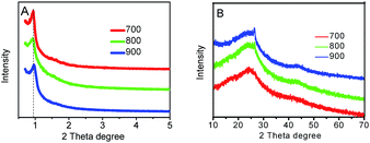 | ||
| Fig. 2 The small-angle (A) and large-angle (B) XRD patterns of mesoporous Co–N–GC-700, Co–N–GC-800, and Co–N–GC-900. | ||
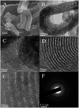 | ||
| Fig. 3 SEM (A), TEM (B–D) and high-resolution TEM images (E) of the prepared Co–N–GC-800 and the corresponding selected-area electron diffraction images (SAED) (F). | ||
For examining the degree of graphitization of pore wall in the Co–N–GC, the large-angle XRD patterns of Co–N–GC prepared at different temperatures were measured. The results were shown in Fig. 2B. Two broad peaks ascribing to the (002) and (101) diffraction of graphitic structure at 2θ = 25 and 43° can be observed in Fig. 2B, which indicate the formation of graphitization in pore walls. The peak intensity at 2θ = 25 and 43° increases with the increasing heat-treatment temperatures. It suggests that the higher heat-treatment temperatures can enhance the graphitization degrees of the Co–N–GC frameworks. At the same time, the SAED pattern (Fig. 3F) for Co–N–GC-800 shows clear diffraction rings of graphitic carbon in agree with the graphitic stripes in the high-resolution TEM image (Fig. 3E). These facts proved the appropriate graphitization of pore wall, which could contribute to the improvement of its electron conductivity.
N2-adsorption and desorption isotherms illustrated that the prepared Co–N–GC materials at different temperatures exhibited type-IV isotherms of typical mesoporous material (Fig. 4A). The corresponding parameters are summarized in Table S1.† Among the prepared Co–N–GC materials, Co–N–GC-700 has the highest BET surface area (723 m2 g−1). With the increasing heat-treatment temperature from 700 to 900 °C (Fig. 4B and Table S1†), the pore sizes of the mesoporous Co–N–GC have a slight increasing from 3.9 to 4.7 nm, which also should be ascribed to the shrinkage of the pore walls at higher temperatures. Another prominent trait of the prepared Co–N–GC is the narrow pore-size distribution (Fig. 4B and Table S1†). Such large-pore structures with high surface area may provide a desired support for the catalytic active sites and facilitate the transportation of O2 and infiltration of electrolyte.
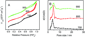 | ||
| Fig. 4 (A) N2-sorption isotherm curves and (B) the corresponding pore size distribution curves for the prepared Co–N–GC-700, Co–N–GC-800, and Co–N–GC-900. | ||
The distribution, the content and chemical environment of the component elements in the surface of the prepared mesoporous Co–N–GC material strongly influence its catalysis activity and the structural stability of active sites. The investigated SEM-EDS mapping revealed a uniform distribution of Co, N, C and O atoms in the surface of these Co–N–GC materials (Fig. S2†). Its uniform distribution is obviously different from the analogue materials reported in the literature, such as metal complex decorated ZIF materials,42 N-self-doped graphene-based nonprecious Fe catalyst (Fe–N–graphene),43 catalysts prepared by pyrolyzing various metal–nitrogen–carbon precursors,44 CoDETA/C catalyst prepared by pyrolyzing cobalt diethylenetriamine chelate on carbon.45 The soluble Co–porphyrin complexes as the precursors may easily be filled into the channels of hard templates, efficiently decrease the formation of non-uniform mesostructured structures and large bulk particles and give an opportunity to enhance their density of active sites.
Typically, the XPS results (Table S2†) reveal that the Co–N–GC-800 is composed of C, N, O, and Co. The surface N (6.8 at%) and Co (0.6 at%) content of Co–N–GC-800 (Table S2†) is relatively higher than those of the previously reported materials containing Co and N.11,46 The Co content in Co–N–GC catalysts have also been measured by ICP-AES measurements. The weight percentage of Co in Co–N–GC-700, Co–N–GC-800 and Co–N–GC-900 is 3.4, 3.6 and 1.8 wt%, respectively (see ESI†). The lower content of Co in Co–N–GC-900 mainly is due to the degradation of Co–Nx species and formation of Co metal particles at higher temperature, which were leached by HF solution in the preparation process. Three peaks at 780.6 (Co 2p3/2), 785.4 (satellite peak) and 796.2 (Co 2p1/2) eV in the XPS spectrum of Co 2p in Fig. 5 were clearly observed and are similar to the Co 2p XPS of other catalysts containing Co2+ in the literature.47–49 The deconvolution of the N 1s signals gives four peaks with binding energies centred at 398.3, 400.0, 401.2 and 403.5 eV (Fig. 5B), which may be assigned to pyridinic-N (Py-N), pyrrolic-N (Pyr-N), graphitic-N (G-N), and N–O (Py-N+–O−) species, respectively.50,51 Pyridinic and pyrrolic nitrogen atoms can associate with Co ions in the mesoporous framework to form active Co–Nx species for ORR.20,21 The UV-vis diffuse reflection spectrum of Co–N–GC-800 reveals four weak absorption peaks at 458, 560, 586 and 604 nm (Fig. S3†). These peaks are the similar to those of Co porphyrin precursor and the results in the literature,52 and may be assigned to the Co–Nx moiety. It could further confirm the formation of Co–Nx active site in the Co–N–GC-800.
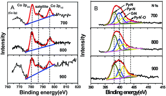 | ||
| Fig. 5 (A) The XPS spectra of Co 2p; (B) N 1s spectra for mesoporous Co–N–GC-700, Co–N–GC-800, and Co–N–GC-900. | ||
Moreover, the relative content of Co and different types of doped nitrogen in the surface of Co–N–GC is also displayed in Table S2.† It also can be seen that the N-graphitic groups possess the higher thermodynamic stability than pyridinic and pyrrolic N groups, just like the description in the literature.53,54 However, the relative amount of pyridinic-N increases with the heat-treatment temperature rising and reach to the maximum value around 800 °C, and then decrease in the prepared samples. This variation tendency is the same as that of Co content in the samples with the heat-treatment temperature rising. It seems to testify that the presence of Co may stabilize pyridinic-N groups in the surface of Co–N–GC. However, increasing the heat-treatment temperature to 900 °C, the degradation and conversion of Co stabilized-pyridinic-N species obviously occurred because of the reduction of the Co ions and led to the decrease of pyridinic-N groups and Co in the surface (the generated Co metal was etched off by acid). The higher content of pyridinic-N and Co in Co–N–GC-800 may contribute to its higher activity for ORR.46
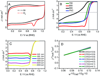
CV experiments over Co–N–GC-800 (Fig. 6A) revealed an obvious diffusion-controlled ORR peak at 0.78 V (vs. RHE) in O2-saturated 0.1 M HClO4 solution55 and is absent in the electrolyte saturated with Ar. Linear sweep voltammetry measurements (LSV) are carried out to evaluate the catalytic performance of the Co–N–GC samples prepared at different temperatures for ORR in 0.1 M HClO4 electrolyte. It can be seen (Fig. 6B) that the Co–N–GC-800 has the highest half-wave potentials (E1/2) and shows the highest catalytic activity for ORR among three Co–N–GC samples. It is reported that Fe-based carbon electrocatalysts have high catalytic performance comparable to Pt/C catalyst in acidic medium, but it is scare for Co-based ORR catalysts. The ORR half-wave potential (E1/2) on the prepared Co–N–GC by us reaches 0.79 V with the catalyst loading of 0.6 mg cm−2, very close to that of Pt/C (20 wt%, Alfa) catalyst (0.81 V, same with that on Pt/C catalysts in literature48) (Fig. 6B). Moreover, the measured current density over the Co–N–GC-800 electrode at 0.2 V is 5.6 mA cm−2, slightly higher than that over the commercial Pt/C (20 wt%, Alfa) (4.9 mA cm−2; catalyst loading: 0.1 mg cm−2) (Fig. 6B). These results indicated that the activity of the Co–N–GC-800 is comparable to the Pt/C catalysts and higher than some Co-based catalysts such as Co–Nx–C (Ep = 0.71 V),20 CoDETA/C catalyst (Ep = 0.72 V),45 PANI–Co–CNT (Ep = 0.62 V),56 Co–PPy–TsOH/C (Ep = 0.69 V)57 for ORR in acidic medium (Ep: peak potential).
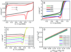
Moreover, the catalytic performance of the prepared Co–N–GC for ORR was also investigated in 0.1 M KOH electrolyte saturated with O2. The results testify that Co–N–GC-800 has the highest activity for ORR among three Co–N–GC samples (Fig. S4†) A well-defined cathodic peak appears at around 0.83 V (vs. RHE) in CV curve over Co–N–GC-800 in the electrolyte saturated with O2 and is absent in the electrolyte saturated with Ar, as shown in Fig. 7A. The ORR half-wave potential on Co–N–GC-800 (0.81 V) is only slightly more negative than that over Pt/C (20 wt%, Alfa; Fig. 7B) catalyst (0.82 V, same with that on Pt/C catalysts reported in literature52). However, this E1/2 value is significantly superior to previously reported Co–N/C materials, Co–N–GN (E1/2 = 0.78 V),58 Co–N–C900 (E1/2 = 0.78 V).59 The ORR current density on Co–N–GC-800 electrode measured at 0.8 V is 3.0 mA cm−2 with catalyst loading of 0.2 mg cm−2 and close to that on Pt/C (3.1 mA cm−2; catalyst loading: 0.1 mg cm−2) (Fig. 7B). These facts have sufficiently displayed the high intrinsic activity of Co–N–GC-800 for ORR in a wide pH range of aqueous values.
Higher catalytic activity of Co–N–GC for ORR mainly attribute to the optimized balance between the performance of activity sites, the amount of active site, and the transportation of electron and substrate. With the increasing of the heat-treatment temperature, the graphitization degree of carbon walls in the Co–N–GC is improved and is beneficial to the transportation of electron. However, the higher temperature also generally facilitates the degradation or removal of active Co and N species and leads to the content of them decreases. For example, when heat-treatment temperature increases from 700 to 800 °C, the content of Co decreases from 0.5 to 0.2 at% and from 8.1 to 3.5 at% for N in the prepared Co–N–GC as shown in Table S2.† At the same time, the surface area decrease from 723 to 622 m2 g−1 (Table S2†). Although Co–N–GC-900 has the higher degree of graphitization than Co–N–GC-800, both the lower active Co and N content (especially Co–Nx species) and the lower surface area contributed to the lowest activity among the prepared Co–N–GC materials. For Co–N–GC-700, the lower graphitization degree of carbon framework and the relative low amount of Co–Nx species were detrimental to its catalytic activity for ORR. As a result, Co–N–GC-800 showed the most optimized activity for ORR in both acidic and alkaline media. In addition, higher ORR activity of Co–N–GC-700 than Co–N–GC-900 should be ascribed to its higher active N and Co content (especially Co–Nx species) and the larger surface area.
Because Co–N–GC-800 material possesses excellent activity for ORR, the ORR kinetic process on it has also been investigated in both alkaline and acidic media. Firstly, polarization curves at different rotating speeds were recorded from 0 to 1.1 V with a scan rate of 10 mV s−1 to study the kinetics of the catalyzed ORR over Co–N–GC-800 in 0.1 M HClO4 electrolyte (Fig. 6C). The current densities sharply increase with the rotating speeds (from 400 to 2500 rpm) in the mixed kinetic-diffusion control region in the potential range of 0.7 to 0.9 V, indicating an efficient diffusion of the reactants in the catalysts, followed by a hump peak at the LSV of this Co–N–GC in both alkaline and acidic media. This phenomenon maybe arises from the insufficient compensation of O2 concentration adsorbed on the inner surface of the catalyst layer after the accumulative oxygen within the catalyst layer by adsorption is depleted at more negative potential, which is similar to the results reported in the literature.60,61 The subsequent current plateau exhibits a diffusion-limited kinetic process for ORR in the potential range of 0 to 0.6 V (Fig. 6B and C). To further explain the ORR catalyzed by Co–N–GC-800 modified electrodes, the LSV data were analyzed using the Koutecky–Levich (K–L) equation (eqn (1)). The corresponding K–L plots from the RDE polarization curves over Co–N–GC-800 in 0.1 M HClO4 electrolyte (Fig. 6D) exhibited good linearity between 0 and 0.6 V. The number of electron transferred was calculated to be 3.9 on the basis of the K–L equations at 0.5 V (B = 0.62nFC0(D0)2/3ν−1/6, C0 = 1.18 × 10⁻³ mol L−1, D0 = 1.9 × 10⁻⁵ cm s−1, ν = 0.0893 cm2 s−1).62 The same phenomena also have been observed in the in alkaline medium (Fig. 7C). The K–L plots in 0.1 M KOH electrolytes also exhibited good linearity from 0.1 to 0.7 V (Fig. 7D). The corresponding number of electron transferred at 0.6 V was calculated to be 4.0 using the K–L equation (B = 0.62nFC0(D0)2/3ν−1/6, C0 = 1.2 × 10⁻³ mol L−1, D0 = 1.9 × 10⁻⁵ cm s−1, ν = 0.01 cm2 s−1).63 These facts verify that Co–N–GC-800 can efficiently catalyze the reaction of oxygen reduction by in a direct nearly four-electron-reduction pathway at low overpotential in acid and alkaline media.
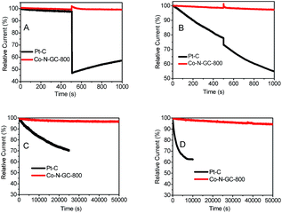
The methanol-tolerance of the cathode catalyst is one of the major concerns in a direct-methanol fuel cell. To examine the effect of methanol crossover on the cathode behavior, we investigate the electrocatalytic selectivity of the prepared Co–N–GC catalysts and Pt/C against the oxidation of methanol in both O2-saturated alkaline (0.1 M KOH) and acidic (0.1 M HClO4) media in the presence of methanol (the final concentration of methanol injected into the electrolyte is 3.0 M). After the injection of methanol, no significant changes are observed in the ORR current density over Co–N–GC-800 catalysts in both acidic (Fig. 8B) and alkaline media (Fig. 8A). But whether in acidic or alkaline medium, the ORR current density over the commercial Pt/C catalyst significantly decreases (Fig. 8A and B), because of its inherent disadvantage of Pt electrocatalyst that has vulnerability to methanol attack.64 The experimental results demonstrate that the Co–N–GC-800 catalysts possess the selectivity for ORR and methanol-tolerance performance superior to Pt/C catalyst.
The investigated results for the durability of the prepared Co–N–GC-800 catalyst in acidic and alkaline media were shown in Fig. 8C and D. From the corresponding chronoamperometric, it can be seen that after running for 50![[thin space (1/6-em)]](https://www.rsc.org/images/entities/char_2009.gif) 000 s in 0.1 M KOH and 0.1 M HClO4, it shows insignificant decay (about 2% and 5%) in current density on the Co–N–GC-800 electrodes at 0.55 and 0.57 V. The commercial Pt/C catalyst suffers from 30% loss of current density after running for 25
000 s in 0.1 M KOH and 0.1 M HClO4, it shows insignificant decay (about 2% and 5%) in current density on the Co–N–GC-800 electrodes at 0.55 and 0.57 V. The commercial Pt/C catalyst suffers from 30% loss of current density after running for 25![[thin space (1/6-em)]](https://www.rsc.org/images/entities/char_2009.gif) 000 s in 0.1 M KOH (Fig. 8C) and 37% loss after running for 10
000 s in 0.1 M KOH (Fig. 8C) and 37% loss after running for 10![[thin space (1/6-em)]](https://www.rsc.org/images/entities/char_2009.gif) 000 s in 0.1 M HClO4 (Fig. 8D). Thus the durability of the prepared Co–N–GC-800 electrodes is not only higher than the commercial Pt/C catalyst, but also better than many analogous Co-based catalysts, Co/N–C-800 (retains a relative current of 95.8% after 10
000 s in 0.1 M HClO4 (Fig. 8D). Thus the durability of the prepared Co–N–GC-800 electrodes is not only higher than the commercial Pt/C catalyst, but also better than many analogous Co-based catalysts, Co/N–C-800 (retains a relative current of 95.8% after 10![[thin space (1/6-em)]](https://www.rsc.org/images/entities/char_2009.gif) 000 s in O2-saturated 0.1 M KOH),65 Co1.12/N2.92/C-700 (retains a relative current of 90.5% and 86% after 18
000 s in O2-saturated 0.1 M KOH),65 Co1.12/N2.92/C-700 (retains a relative current of 90.5% and 86% after 18![[thin space (1/6-em)]](https://www.rsc.org/images/entities/char_2009.gif) 000 s in O2-saturated 0.1 M KOH and 0.1 M HClO4 respectively).66
000 s in O2-saturated 0.1 M KOH and 0.1 M HClO4 respectively).66
4. Conclusions
In summary, we have successfully fabricated an efficient Co-based carbon electrocatalyst for ORR in a wide pH range. By a wet-impregnation nanocasting method with a water-soluble macromolecules containing Co–Nx moieties as the only precursor, the prepared Co–N–GC catalyst with ordered mesoporous exhibited high degree of graphitization, a high accessible surface area and large-pore channels for the transportation of electron O2. The special precursor and the optimized heat-treatment process created high density ORR active sites in the graphite framework of the catalysts. The CV and RDE polarization curves confirmed positive ORR E1/2 values and higher current density of the Co–N–GC-800 Co-based electrocatalysts in 0.1 M HClO4 and 0.1 M KOH electrolyte, comparable to commercial Pt/C. This Co–N–GC-800 catalyst could somehow steer a complete reduction of O2 to H2O in four-electron process, and exhibit long-time stability toward ORR in both media as well as the excellent methanol resistance. This Co-based catalyst may serve as a promising alternative to Pt/C catalysts for the ORR in the widespread implementation of PEFCs.Acknowledgements
The authors are grateful to financial support from China National Natural Science Foundation (No. 21303058), Shanghai Municipal Natural Science Foundation (No. 13ZR1412400), and the key project of Shanghai Science and Technology Committee (No. 11JC1403400 and 14231200300).Notes and references
- G. Wu and P. Zelenay, Acc. Chem. Res., 2013, 46, 1878–1889 CrossRef CAS PubMed.
- F. Jaouen, E. Proietti, M. Lefevre, R. Chenitz and J. P. Dodelet, Energy Environ. Sci., 2011, 4, 114–130 CAS.
- Z. Chen, D. Higgins and A. Yu, Energy Environ. Sci., 2011, 4, 3167–3192 CAS.
- A. Rabis, P. Rodriguez and T. J. Schmidt, ACS Catal., 2012, 2, 864–890 CrossRef CAS.
- G. Wu, G. F. Cui and D. Y. Li, J. Mater. Chem., 2009, 19, 6581–6589 RSC.
- C. H. Choi, C. Baldizzone and J. P. Grote, Angew. Chem., Int. Ed., 2015, 54, 12753–12757 CrossRef CAS PubMed.
- S. Wang, M. Zhu and X. Bao, ChemCatChem, 2015, 7, 2937–2944 CrossRef CAS.
- Y. W. Ju, S. Yoo and C. Kim, Adv. Sci., 2016, 3, 1500205 Search PubMed.
- J. Sa, C. Park, H. Y. Jeong, S. H. Park, Z. Lee, K. T. Kim, G. G. Park and S. H. Joo, Angew. Chem., Int. Ed., 2014, 53, 4102–4106 CrossRef PubMed.
- D. Zhou, L. Yang and L. Yu, Nanoscale, 2015, 7, 1501–1509 RSC.
- J. H. Lee, M. J. Park and S. J. Yoo, Nanoscale, 2015, 7, 10334–10339 RSC.
- Y. Zhai, C. Zhu and E. Wang, Nanoscale, 2014, 6, 2964–2970 RSC.
- Z. Liu, L. Ji and X. Dong, RSC Adv., 2015, 5, 6259–6264 RSC.
- Z. Ma, C. Guo, Y. Yin, Y. Zhang, H. Wu and C. Chen, Electrochim. Acta, 2015, 160, 357–362 CrossRef CAS.
- P. D. Tran, A. Morozan and S. Archambault, Chem. Sci., 2015, 6, 2050–2053 RSC.
- L. Yang, N. Larouche and R. Chenitz, Electrochim. Acta, 2015, 159, 184–197 CrossRef CAS.
- G. Wu, K. L. More, C. M. Johnston and P. Zelenay, Science, 2011, 332, 443–447 CrossRef CAS PubMed.
- A. G. Kong, B. Dong, X. F. Zhu and Y. K. Shan, Chem.–Eur. J., 2013, 19, 16170–16175 CrossRef CAS PubMed.
- A. G. Kong, X. F. Zhu, Z. Han and Y. K. Shan, ACS Catal., 2014, 4, 1793–1800 CrossRef CAS.
- A. G. Kong, Y. Y. Kong, X. F. Zhu and Y. K. Shan, Carbon, 2014, 78, 49–59 CrossRef CAS.
- S. Li, L. Zhang and J. Kim, Electrochim. Acta, 2010, 55, 7346–7353 CrossRef CAS.
- R. Jasinski, Nature, 1964, 201, 1212–1213 CrossRef CAS.
- A. Widelov, Electrochim. Acta, 1993, 38, 2493–2502 CrossRef CAS.
- G. Lalande, G. Faubert, R. Cote, D. Guay and J. P. Dodelet, J. Power Sources, 1996, 61, 227–237 CrossRef CAS.
- F. Jaouen, M. Lefevre, J. P. Dodelet and M. Cai, J. Phys. Chem. B, 2006, 110, 5553–5558 CrossRef CAS PubMed.
- C. W. B. Bezerra, L. Zhang, K. Lee, H. Liu, A. L. B. Marques, E. P. Marques, H. Wang and J. Zhang, Electrochim. Acta, 2008, 53, 4937–4951 CrossRef CAS.
- G. Faubert, R. Côté, J. P. Dodelet, M. Lefèvre and P. Bertrand, Electrochim. Acta, 1999, 44, 2589–2603 CrossRef CAS.
- H. J. Zhang, X. Yuan, W. Wen, D. Y. Zhang, L. Sun, Q. Z. Jiang and Z. F. Ma, Electrochem. Commun., 2009, 11, 206–208 CrossRef CAS.
- K. Asazawa, H. Kishi and H. Tanaka, J. Phys. Chem. C, 2014, 118, 25480–25486 CAS.
- C. Shi, B. Steiger, M. Yuasa and F. C. Anson, Inorg. Chem., 1997, 36, 4294–4295 CrossRef CAS PubMed.
- C. N. Shi and F. C. Anson, Inorg. Chem., 1998, 37, 1037–1043 CrossRef CAS.
- F. C. Anson, E. H. Song and C. N. Shi, Langmuir, 1998, 14, 4315–4321 CrossRef.
- M. Yuasa, R. Nishihara, C. Shi and F. C. Anson, Polym. Adv. Technol., 2001, 12, 266–270 CrossRef CAS.
- H. Tang, H. Yin and J. Wang, Angew. Chem., 2013, 125, 5695–5699 CrossRef.
- J. M. You, H. S. Han and H. K. Lee, Int. J. Hydrogen Energy, 2014, 39, 4803–4811 CrossRef CAS.
- N. C. Cheng, C. Kemna, S. Goubert-Renaudin and A. Wieckowski, Electrocatalysis, 2012, 3, 238–251 CrossRef CAS.
- M. Chokai, M. Taniguchi, S. Moriya, K. Matsubayashi and T. Shinoda, J. Power Sources, 2010, 95, 5947–5951 CrossRef.
- Y. Hu, X. Zhao, Y. Huang, Q. Li and N. J. Bjerrum, J. Power Sources, 2013, 225, 129–136 CrossRef CAS.
- W. Orellana, J. Phys. Chem. C, 2013, 117, 9812–9818 CAS.
- S. Jun, S. H. Joo, R. Ryoo, M. Kruk and M. Jaroniec, J. Am. Chem. Soc., 2000, 112, 10712–10713 CrossRef.
- D. Zhao, J. Feng and Q. Huo, Science, 1998, 279, 548–552 CrossRef CAS PubMed.
- D. Zhao, J. L. Shui and L. R. Grabstanowicz, Adv. Mater., 2014, 26, 1093–1097 CrossRef CAS PubMed.
- C. He, J. J. Zhang and P. K. Shen, J. Mater. Chem. A, 2014, 2, 3231–3236 CAS.
- U. Tylus, Q. Jia and K. Strickland, J. Phys. Chem. C, 2014, 118, 8999–9008 CAS.
- H. J. Zhang, H. Li and X. Li, Int. J. Hydrogen Energy, 2014, 39, 267–276 CrossRef CAS.
- L. Osmieri, A. H. A. M. Videla and S. Specchia, J. Power Sources, 2015, 278, 296–307 CrossRef CAS.
- Z. Yin, T. Hu and J. Wang, Electrochim. Acta, 2014, 119, 144–154 CrossRef CAS.
- X. Yuan, H. C. Kong and Y. J. He, Int. J. Hydrogen Energy, 2014, 39, 16006–16014 CrossRef CAS.
- W. Bian, Z. Yang and P. Strasser, J. Power Sources, 2014, 250, 196–203 CrossRef CAS.
- S. Jiang, C. Zhu and S. Dong, J. Mater. Chem. A, 2013, 1, 3593–3599 CAS.
- Y. Zhai, C. Zhu and E. Wang, Nanoscale, 2014, 6, 2964–2970 RSC.
- M. Shen, L. R. Zheng and W. He, Nano Energy, 2015, 17, 120–130 CrossRef CAS.
- M. Favaro, L. Perini and S. Agnoli, Electrochim. Acta, 2013, 88, 477–487 CrossRef CAS.
- V. Perazzolo, C. Durante and R. Pilot, Carbon, 2015, 95, 949–963 CrossRef CAS.
- R. H. Wopschall, Anal. Chem., 1967, 39, 1514–1527 CrossRef CAS.
- Z. Yin, T. Hu and J. Wang, Electrochim. Acta, 2014, 119, 144–154 CrossRef CAS.
- X. Yuan, H. C. Kong and Y. J. He, Int. J. Hydrogen Energy, 2014, 39, 16006–16014 CrossRef CAS.
- S. Jiang, C. Zhu and S. Dong, J. Mater. Chem. A, 2013, 1, 3593–3599 CAS.
- Y. Zhai, C. Zhu and E. Wang, Nanoscale, 2014, 6, 2964–2970 RSC.
- W. Wei, H. Liang and K. Parvez, Angew. Chem., 2014, 126, 1596–1600 CrossRef.
- H. D. Sha, X. Yuan and X. X. Hu, J. Electrochem. Soc., 2013, 160, F507–F513 CrossRef CAS.
- M. Shen, L. R. Zheng and W. He, Nano Energy, 2015, 17, 120–130 CrossRef CAS.
- R. Liu, D. Wu and X. Feng, Angew. Chem., 2010, 122, 2619–2623 CrossRef.
- Z. H. Wen, J. Liu and J. H. Li, Adv. Mater., 2008, 20, 743–747 CrossRef CAS.
- Y. Su, Y. Zhu and H. Jiang, Nanoscale, 2014, 624, 15080–15089 RSC.
- Y. Yang, J. Liu and Y. Han, Phys. Chem. Chem. Phys., 2014, 16, 25350–25357 RSC.
Footnote |
| † Electronic supplementary information (ESI) available: Fig. S1–S4; Tables S1 and S2. See DOI: 10.1039/c5ra25862f |
| This journal is © The Royal Society of Chemistry 2016 |


