Seeding of Au on CdSe/CdS nanoplates using Langmuir–Blodgett technique†
Subhasis Dasa,
Biswarup Satpati b,
Himani Chauhanc,
Sasanka Dekac,
Manoj Kumar Ghosalyad,
Chinnakonda S. Gopinathd and
Tanushree Bala*a
aDepartment of Chemistry and Centre for Research in Nanoscience and Nanotechnology (CRNN), University of Calcutta, 92 A.P.C. Road, Kolkata-700009, India. E-mail: tanushreebala@gmail.com
bSurface Physics Division, Saha Institute of Nuclear Physics, 1/AF Bidhannagar, Kolkata-64, India
cDepartment of Chemistry, University of Delhi, New Delhi-110007, India
dCatalysis Division and Center of Excellence on Surface Science, CSIR – National Chemical Laboratory, Pune-411 008, India
First published on 18th January 2016
Abstract
Oleyl amine capped CdSe/CdS nanoplates were synthesized by hot injection technique which formed a stable monolayer over both a water subphase and an aqueous HAuCl4 subphase using a Langmuir–Blodgett trough. Au islands were generated at the edge as well as on one specific surface of the flat nanoplates by exploiting the reducing capacity of oleyl amine to form Au nanoseeds from AuCl4− ions. The initial Au nanoseeds changed to a shell surrounding these nanoplates on prolonged exposure to the subphase containing the Au precursor. Monolayer of the hybrid structures was deposited onto suitable substrates for characterization by a number of different techniques and to study the photocatalytic activity. The same substrate with the monolayers could be re-used in several cycles of photocatalysis.
1. Introduction
Encouraged by the possibility of tuning the band gap and hence the optical and electronic properties of semiconductor nanomaterials by varying their size, there has been much interest in the synthesis of pure colloidal semiconductors and their hybrids with other semiconductor materials or noble metals (Au, Ag or Pt). The synthesis of semiconductor materials with regular shapes, such as spherical dots, rods,1 wires,2 cubes,3 hexagonal nanoplates,4 tetrapods,5 etc. has been reported. Apart from variations in shape and size, another direction of research into semiconductor nanomaterials is the synthesis of type I (where the electron–hole pair remains confined to the lowest energy state of the material) and type II (where the lowest energy states of the holes and electrons are spatially separated) core–shell structures. Semiconductor–noble metal heterojunctions have been investigated widely due to the possibility of charge, energy or even spin transfer.6 The quenching of emission in such hybrids is indicative of electron transfer from the conduction band of the semiconductor to the metal, allowing exciton separation and their use in solution for photocatalysis and redox chemistry,7,8 or in the solid state for nanoscale electrical contacts.9,10 The formation of a metal shell over a semiconductor core,11–13 a metal–semiconductor sandwich architecture,14 or the growth of metal islands over the semiconductor surface or selectively at the ends of rods are all examples of such heterojunctions. These are achieved mainly via high-temperature synthesis,15 lithography,16 epitaxial growth techniques17 or electrochemical methods.18 Zero-dimensional quantum dots (QDs) or rods are generally preferred for these heterojunctions, although 2D flat structures are also potential candidates. Various synthetic methods have been used to fabricate different types of hybrids19–23 with different dimensionalities.24–27 Most of these are solution-based techniques associated with high temperatures and the use of toxic chemicals. Thus separation of this product from the solvent and their assembly on a suitable substrate for application remain challenging.We report here the seeding of Au on CdSe/CdS nanoplates via a Langmuir–Blodgett (LB) technique, which is relatively unusual for the synthesis of this kind of hybrids. The LB technique is well-established as a method to generate long-range close-packed assemblies of nanomaterials that are able to spread over a water subphase in the form of a Langmuir monolayer. Oleyl amine capped CdSe/CdS nanoplates are found to an appropriate candidate for long-range assembly via the LB technique. The amine group of the capping agent attaches itself to the CdSe/CdS nanoplates, with its hydrophobic tail protruding outwards. This orientation had a two-fold advantage in our experiment: (1) it rendered the CdSe/CdS nanoplates hydrophobic and able to float on an aqueous subphase; and (2) the amine group is already known for its ability to reduce AuCl4− ions to Au0. Thus the replacement of a pure water subphase with an aqueous solution of chloroauric acid will allow the growth of Au(0) seeds over the CdSe/CdS nanoplates. The formation of Au seeds is compelled to be direction-specific as the CdSe/CdS nanoplates relinquish their orientational flexibility when they are in a close-packed assembly in an LB trough determined by surface pressure–area (Π–A) isotherms. It is also an advantage of the LB technique that the hybrid monolayer can be transferred to any substrate, such as quartz, Si(111) or glass, with full control over the number of monolayers deposited. Hybrids deposited over quartz have been investigated for their photocatalytic activity and present a very interesting result compared with pristine CdSe/CdS nanoplates; the catalyst (CdSe/CdS–Au hybrids) can be re-used over several cycles. The formation of the hybrids and the photocatalysis were followed using several different characterization techniques, including UV-visible spectrophotometry, fluorescence spectrometry, X-ray photoelectron spectrometry (XPS), transmission electron microscopy (TEM), high-resolution (HR) TEM, energy-dispersive X-ray spectrometry (EDAX) and scanning TEM (STEM)-high-angle annular dark field (HAADF) analysis.
2. Experimental section
Chemicals used
Selenium powder (Se, 99.99%), sulphur powder (S, 99.99%) and trioctylphosphine (99%) were purchased from Strem Chemicals (USA). Cadmium oxide (CdO, 99.5%), oleyl amine (OLAM, 70%), HAuCl4, 1-octadecene (90%), oleic acid (90%) and trioctylphosphine oxide (TOPO, 99%) were purchased from Sigma-Aldrich (USA). n-Hexylphosphonic acid (>97%) and n-octadecylphosphonic acid (ODPA, >97%) were purchased from Plasma Chem (Germany). Anhydrous methanol, toluene and chloroform were purchased from Thomas Baker (India). All chemicals were used as received without further purification.Two-step synthesis of 2D CdSe/CdS nanohetroplatelets
2D CdSe/CdS nanohetroplatelets were synthesized using a two-step colloidal synthesis method as reported previously.27 CdSe QDs were synthesized first; after that, CdS shells were grown over the CdSe QDs by a seeded growth method at a high temperature. To synthesize the CdSe seeds, a mixture of 0.128 g of CdO, 2 g of TOPO, 2 ml of oleic acid and 5 ml of 1-octadecene were added to a 50 ml three-necked flask and heated at 150 °C for 1 h under vacuum, followed by heating to 300 °C under an N2 atmosphere to obtain a Cd precursor solution. A solution containing 1.5 mmol of elemental Se (0.118 g) in 1 ml of OLAM (from a glove box under an N2 atmosphere) was injected instantly into this hot Cd precursor solution using a large needle syringe. The reaction was stopped by removing the heating mantle at 0 s and anhydrous toluene (5 ml) was added to allow the reaction mixture to cool to room temperature. The orange-red product of crude CdSe QDs was precipitated by adding anhydrous methanol, followed by centrifugation and redispersion in 1 ml of anhydrous toluene or oleylamine for further use. The concentration of CdSe QDs in 1 ml of OLAM was calculated to be 4.34 × 10⁻⁴ M.The second step was the seeded growth of the CdS shell over the as-synthesized CdSe QDs. A CdSe/S/OLAM stock solution was prepared by dissolving elemental S powder (0.06 g) in OLAM (1.07 g) in a glove box with heating and stirring. Then 300 μl of CdSe QDs in OLAM solution were added. Next, the Cd precursor solution was prepared in a three-necked round-bottomed flask by degassing a mixture of CdO (0.03 g), TOPO (1.5 g), n-octadecylphosphonic acid (0.144 g) and n-hexylphosphonic acid (0.4 g) at 150 °C for 1 h; the temperature was then increased to 335 °C under an N2 atmosphere. To this transparent solution, 1 g of OLAM (from the glove box) was added. As the temperature reached 335 °C, the CdSe/S/OLAM stock solution was injected rapidly with a large needle syringe and the reaction was stopped at 7 min by removing the heating mantle and instantly adding anhydrous toluene (5 ml). The yellowish orange CdSe/CdS nanocrystal product was precipitated by adding anhydrous methanol, followed by centrifugation. The CdSe/CdS nanocrystals finally obtained were dispersed in 1 ml of anhydrous toluene for the growth of Au seeds.
Study of surface pressure–area isotherms
The as-synthesized CdSe/CdS nanoplates were centrifuged several times to remove any uncoordinated organic molecules (OLAM) and the sample collected from the pellet was rotary-evaporated and thoroughly dried to achieve a solvent-free product. The nanoplates were then dispersed in chloroform at a concentration of 1 mg ml−1. A KSV NIMA medium trough was thoroughly cleaned with water and isopropyl alcohol and the dry trough was then filled with deionized water. The surface of the water was cleaned of dust particles before a 5 μl volume of the 1 mg ml−1 solution of CdSe/CdS nanoplates in chloroform was spread on the surface. After waiting of 10 min for the complete evaporation of the solvent, surface pressure–area (Π–A) isotherms were recorded with increasing volumes of CdSe/CdS spread over the water subphase. Π–A isotherms were also measured at different time intervals of 10 min, 6 h and 12 h while keeping the volume constant at 15 μl over water and also over a 5 × 10⁻⁵ M aqueous HAuCl4 subphase in separate experiments.Formation of metal (Au) seeds on CdSe/CdS nanoplates
Keeping all other experimental conditions the same, the trough was filled with a 5 × 10⁻⁵ M aqueous solution of HAuCl4. Π–A isotherms were recorded with 15 μl of CdSe/CdS nanoplates in CHCl3 following 2 min of standing time for evaporation of the solvent after spreading the sample; the barriers were compressed at a rate of 10 mm min−1. The evaporation time was modified from that of pristine CdSe/CdS over a water subphase because, as the monolayer was already in contact with the reactant, the reaction was expected to start immediately after spreading. The barriers were kept at the maximum surface pressure for 12 h to ensure the formation of a compact monolayer. The monolayer of the hybrid was deposited at a rate of 5 mm min−1 at a constant surface pressure of 10 mN m−1 on various substrates, such as Si(111) and quartz, for characterization. Twenty monolayers of the hybrid were deposited with a time gap of 10 min between successive dips to dry the layer on the substrates before characterization. A monolayer was also deposited on carbon-coated copper grids for TEM analysis via a single vertical dip.Study of photocatalytic activity
A methylene blue solution was selected to measure the photocatalytic activity as this chemical is known to be photodegraded under visible light irradiation in the presence of a catalyst. The intensity of the colour of the methylene blue solution decreased with time as it was degraded, which could be easily monitored by measuring the absorbance of the solution. A clean quartz plate was deposited with 20 monolayers by fixing the surface pressure at 10 mN m−1 when the CdSe/CdS nanoplates were spread over the water subphase. This plate was dipped in 50 ml of a 5 × 10⁻⁶ M methylene blue solution and stored under normal sunlight. The degradation of methylene blue was monitored by removing 2.5 ml aliquots at time intervals of 15 min to measure the UV-visible absorption spectra. A similar photocatalytic experiment was carried out with monolayers of the hybrids deposited on quartz. The rate of the reaction was measured from the slope of the ln(A0/At) vs. time (t) plot, where A0 and At were the absorbance of methylene blue at time t = 0 min and t = t min, respectively.3. Characterization
UV-visible-NIR spectrometry
CdSe/CdS nanoplates were deposited on a clean quartz plate from the monolayer formed on the water subphase in the LB trough. Their spectra were measured using a Jasco UV-visible spectrophotometer (V570 UV-VIS-NIR) operated at a resolution of 2 nm. Similar measurements were performed after the formation of the hybrid nanostructures using the LB technique after deposition on a quartz plate.Photoluminescence spectrometry
CdSe/CdS nanoplates were deposited on a clean quartz plate from the Langmuir monolayer formed on the water subphase in the LB trough. The emission spectra were then recorded using a Perkin-Elmer LS55 fluorescence spectrometer with excitation at λex = 450 nm. Similar measurements were performed using the hybrid samples.Transmission electron microscopy
TEM was carried out using an FEI Tecnai G2 F30 S-Twin microscope operated at 300 kV. The microscope was equipped with a Fischione Model 3000 HAADF detector and a scanning unit. The compositional analyses were performed using an EDX (EDAX Inc.) attachment in the same microscope. Samples for analysis were prepared by depositing a Langmuir film on carbon-coated copper grids at different time intervals to assess the growth of Au on the CdSe/CdS nanoplates; the samples were thoroughly dried in air.X-ray photoelectron spectrometry
XPS measurements were made using a custom-built ambient pressure XPS system from Prevac equipped with a VG Scienta monochromator (MX650) using an Al Kα anode (1486.6 eV).28 The energy of the photoelectrons was determined using a VG Scienta R3000HP differentially pumped analyser. The spectra were recorded at a pass energy of 50 eV.4. Results and discussion
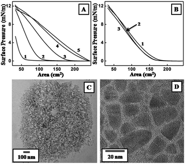
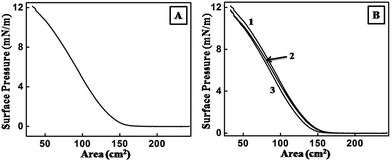
It was important to form a stable monolayer of one of the reacting species over the aqueous solution of the other in order to study the reactions over the LB trough. OLAM capped CdSe/CdS nanoplates formed by the described method formed a stable monolayer over the aqueous subphase, which was determined by the Π–A isotherm over water (Fig. 1A). A maximum surface pressure of 12.1 mN m−1 was achieved by successively increasing the amount of CdSe/CdS nanoplates from 5 to 10 and then to 15 μl (Fig. 1A, curves 1–3). The highest surface pressure remained the same on further addition of the nanoplates up to 25 μl (Fig. 1A, curves 4 and 5). A reduction in the gas phase part of the isotherm ensured extended surface coverage with the addition of the excess nanoplates. The Π–A isotherm over the same subphase with 15 μl of CdSe/CdS was also monitored at time intervals of 10 min, 6 h and 12 h (Fig. 1B). The nature of the isotherms remained similar; the curves could almost be superimposed, indicating the stability of the nanoplates over the water subphase. TEM analysis of the sample was carried out by depositing the monolayer on a carbon-coated copper grid using the LB technique (Fig. 1C and D). Domains of OLAM capped CdSe/CdS nanoplates were observed within which the nanoplates were found to be well organized; OLAM was thought to play a crucial role in this assembly.The ability of the nanoplates to form a monolayer prompted us to check their stability over an aqueous solution of 5 × 10⁻⁵ M HAuCl4. The maximum surface pressure was 12.1 mN m−1 on the addition of 15 μl of nanoplates (Fig. 2A). A typical Π–A isotherm at different time intervals (10 min, 6 h and 12 h) generated superimposed curves (Fig. 2B). Fig. 2A and B jointly prove the formation of a stable monolayer of CdSe/CdS nanoplates over the subphase of aqueous HAuCl4 for a long interval of time, which opened up the opportunity to continue the reaction for a longer period of time. The reaction started at the moment that the nanoplates were spread over the subphase. OLAM served as the capping agent for the nanoplates and also acted as a reducing agent for the chloroaurate ions to form gold seeds.29 The nanoplates were expected to have only bound OLAM because, prior to the formation of the monolayer, the sample was thoroughly purified to remove any excess free OLAM. Thus gold seeds could form only site -selectively on the nanoplates. Thus the deposition of the monolayer on the surface was carried out at various time intervals by the LB technique on substrates suitable for characterization.
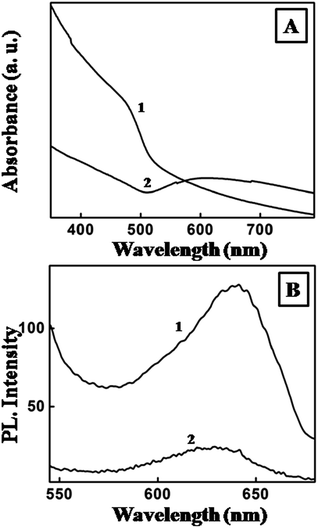
The UV-visible-NIR spectra recorded from a pristine CdSe/CdS nanoplate monolayer showed a peak at 476 nm (curve 1, Fig. 3A), whereas a broad peak over 500–700 nm and centred at ca. 590 nm was obtained from hybrids (curve 2, Fig. 3A). This clearly indicated the reduction of chloroaurate ions to form Au nanoseeds.30 The PL peak for the CdSe/CdS nanoplates was centred at c. 640 nm after exciting the sample at λex = 450 nm (curve 1, Fig. 3B). The emission was heavily quenched after the formation of the hybrids (curve 2, Fig. 3B). Quenching of the PL intensity after formation of the hybrids has been reported previously31 and is thought to be due to the efficient transfer of electrons from the semiconductor to the metal seeds.
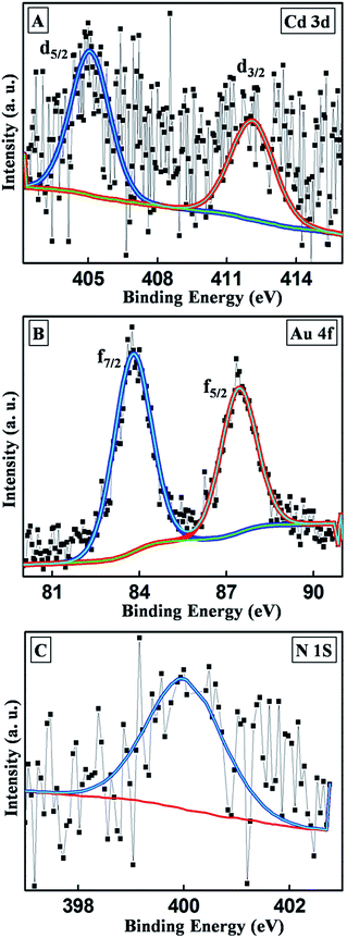
XPS analysis of the hybrids supported the formation of Au0 seeds as suggested by the spectroscopic analyses. The Cd 3d spectra of the hybrids could be fitted with two components corresponding to 3d5/2 and 3d3/2 at binding energies of 405.8 and 412.1 eV, respectively (Fig. 4A). This clearly showed the presence of Cd2+ from the CdSe/CdS nanoplates after hybrid formation. The Au 4f peak was fitted with 4f7/2 and 4f5/2 components at 83.8 and 87.5 eV, respectively, with an energy gap of 3.7 eV (Fig. 4B), confirming the presence of Au0 species on the hybrids. XPS also confirmed the presence of N, which resulted from the presence of the OLAM. An N 1s peak appeared at 399.9 eV (Fig. 4C), which further authenticated the mechanism of formation of the hybrids by exploiting the reducing capability of the OLAM capping agent.32
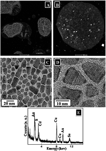
Detailed structural characterizations of the CdSe/CdS nanoplates have been reported previously,27 thus to avoid replication, TEM images were acquired from the monolayer deposited from the surface after 12 h of reaction. The images at very low magnification clearly revealed several domains (Fig. 5A and B) within which the nanoplates were well assembled (Fig. 5C and D). These images also showed the deposition of Au on the borders/edges of the nanoplates, predominantly in a fused ring, with occasional discrete Au seeds on the wider surface of the nanoplates (Fig. 5C and D). The EDX analysis (Fig. 5E) generated peaks for all the relevant elements present in the sample, such as Cd, Se, S and Au.
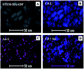
To determine the detailed atomic distribution inside the nanoplates, elemental mapping of Cd and Au was performed using drift-corrected EDX spectrometry with the scanning TEM (STEM)-HAADF technique (Fig. 6). Fig. 6A showed the STEM-HAADF image and the corresponding chemical maps of Cd and Au acquired using Cd L and Au L energies were shown in Fig. 6B and C, respectively. The EDX maps (Fig. 6B–D) were collected with a 2 nm scanning beam. Composite maps of Cd–Au were shown in Fig. 6D, which confirmed the presence of Au in the hybrids.
The major concern in using the LB technique to develop Au seeds on CdSe/CdS nanoplates was the behaviour of seeding when the movement of the monolayer was restricted. We had already demonstrated with QDs33 that such a restriction in movement caused the reactant (here, chloroaurate ions from the subphase) to approach unidirectionally and the growth of Au occurred at the part of the QDs that was in contact with the subphase. If a similar restriction of movement could be induced on the nanoplates by maintaining the surface pressure using the LB technique, then the nanoplates were expected to float flat on the surface as close-packed assembled units (step II, Scheme 1). Such an alignment would allow the chloroaurate ions to access the edges as well as the flat surface of the nanoplates, as shown by the red arrows in step II, Scheme 1. The presence of OLAM reduced AuCl4− to Au seeds at the edges and bottom surface of the nanoplates (step III, Scheme 1). At this stage, the TEM images should show adequate Au nanoseeds on the surface of the nanoplates, not only at the edges. On further prolonged exposure to chloroaurate ions, these small islands of Au might coalesce into a continuous coating at the edges (step IV, Scheme 1), leaving scarce, discrete Au seeds scattered on the surface.
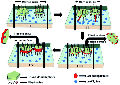 | ||
| Scheme 1 Schematic diagram of a plausible mechanism for the formation of the hybrids via the LB technique. | ||
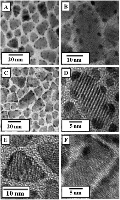
To solve this apparent anomaly, TEM was performed by lifting the monolayer at different time intervals (10 min, 6 h and 12 h). The initial behaviour clearly indicated the formation of Au seeds over all the surface of the nanoplates, including the edges (Fig. 7A and B). A STEM-HAADF (Z-contrast) image supported this (Fig. SI-1†). These seeds grew over time by the well-known Ostwald ripening process and moved towards the edge of the nanoplates as a result of lattice mismatch (Fig. 7C and D). Ultimately, they coalesced to form a shell-like structure surrounding the nanoplates.34 Thus only occasional Au nanoseeds were seen in the sample obtained after 12 h of reaction (Fig. 7E and F). The growth of Au seeds was also shown in in Fig. SI-2.†
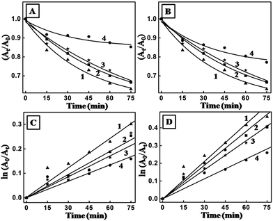
A comparative experiment was performed to demonstrate the superior photocatalytic performance of the hybrids (obtained after 12 h of reaction between the CdSe/CdS monolayer and the HAuCl4 subphase) compared with the CdSe/CdS nanoplates. The experiments were performed for four consecutive cycles for both samples. Measurements of the absorbance at intervals of 15 min over a time span of 75 min showed a reduction in the absorbance maximum of methylene blue at 601 nm when CdSe/CdS was used (Fig. 8A). However, the rate of reduction in the absorbance maximum was definitely more prominent for the hybrids (Fig. 8B). Considering the degradation as following first-order kinetics on the basis of previous reports,35 the rate constants of both samples were estimated from the graph ln(A0/At) vs. time (Fig. 8C and D). The degradation efficiencies of the two samples were calculated according to the following equation:
| D(%) = [(C0 − Ct)/C0] × 100 = [(A0 − At)/A0] × 100 |
| Round | CdSe/CdS | CdSe/CdS–Au | ||
|---|---|---|---|---|
| Rate constant (min−1) | Degradation efficiency (%) | Rate constant (min−1) | Degradation efficiency (%) | |
| 1st | 4.04 × 10⁻³ | 26 | 7.01 × 10⁻³ | 37 |
| 2nd | 3.06 × 10⁻³ | 22 | 6.15 × 10⁻³ | 33.2 |
| 3rd | 2.79 × 10⁻³ | 23.2 | 5.46 × 10⁻³ | 33.5 |
| 4th | 2.25 × 10⁻³ | 14.7 | 4.75 × 10⁻³ | 22.8 |
The hybrid samples definitely had a better photocatalytic effect; the degradation was almost comparable for the first three cycles and a decrease in activity was observed only in the fourth cycle. As the catalysts were deposited on substrates such as a quartz plate, they could easily be separated from the reaction mixture. The plate containing the catalysts was made ready for the next cycle by simple washing with deionized water. This is an advantage over the homogeneous catalytic reaction, where recovery of the used catalysts was limited. The hybrids performed better in the photodegradation than CdSe/CdS as a result of the pronounced charge separation that occurred at the interface between the noble metal and the semiconductor. This study demonstrated the benefit of this metal–semiconductor hybrid structure in photocatalytic applications. The photocatalytic performance was evaluated under natural sunlight/visible light illumination, demonstrating their potential as efficient sunlight-driven photocatalysts in suitable redox reactions.
5. Conclusion
CdSe/CdS nanoplates were seeded with Au using the LB technique. As a result of capping of the OLAM, the CdSe/CdS nanoplates were able to form a Langmuir monolayer. The same capping agent was used for the reduction of chloroaurate ions from the subphase that came into contact with the floating CdSe/CdS nanoplates to form Au seeds. Prolonged exposure helped the growth of small Au seeds to form a continuous Au shell by Ostwald ripening. The reaction with chloroaurate ions was initiated by the close-packed assembly of CdSe/CdS nanoplates obtained using the LB technique. Thus it restricted the movement of the CdSe/CdS nanoplates and directed the seeding procedure. This technique also ensured the controlled transfer of the monolayer over any substrate and simplified the measurement of the photocatalytic activity of the hybrid when used as a catalyst for the decomposition of methylene blue dye. The catalyst could be used over several cycles. The synthesis was carried out at an ambient temperature without the use of any toxic chemicals, which makes this new technique attractive for the generation of similar hybrid materials.Acknowledgements
SD (from CU), HC and MKG thank the University Grant Commission (UGC) for research fellowships. SD (from DU) acknowledges financial support from BRNS-DAE (2011/20/37P/11/BRNS/1733) and CSIR-India (01(2773)/14/EMR-II) and CSG thanks CSIR for partial financial support through CSC-0404 project. TB thanks the Department of Science and Technology (DST, India) for funding through the Fast Track Scheme (SR/FT/CS-106/2011) and the Centre for Research in Nanoscience and Nanotechnology (CRNN), University of Calcutta for instrumental support.References
- X. G. Peng, L. Manna, W. D. Yang, J. Wickham, E. Scher, A. Kadavanich and A. P. Alivisatos, Nature, 2000, 404, 59 CrossRef CAS PubMed.
- M. S. Gudiksen and C. M. Lieber, J. Am. Chem. Soc., 2000, 122, 8801 CrossRef CAS.
- E. Lifshitz, M. Bashouti, V. Kloper, A. Kigel, M. S. Eisen and S. Berger, Nano Lett., 2003, 3, 857 CrossRef CAS.
- S. Ithurria and B. Dubertret, J. Am. Chem. Soc., 2008, 130, 16504 CrossRef CAS PubMed.
- L. Manna, D. J. Milliron, A. Meisel, E. C. Scher and A. P. Alivisatos, Nat. Mater., 2003, 2, 382 CrossRef CAS PubMed.
- H. Zeng, J. Li, J. P. Liu, Z. L. Wang and S. Sun, Nature, 2002, 420, 395 CrossRef CAS PubMed.
- B. Gao, Y. Lin, S. Wei, J. Zeng, Y. Liao, L. Chen, D. Goldfield, X. Wang, Y. Luo, Z. Dong and J. Hou, Nano Res., 2012, 5, 88 CrossRef CAS.
- D. Beydoun, R. Amal, G. Low and S. McEvoy, J. Nanopart. Res., 1999, 1, 439 CrossRef CAS.
- V. R. Reddy, N. R. Reddy and C. J. Choi, Solid-State Electron., 2005, 49, 1213 CrossRef CAS.
- G. S. Lotey and N. K. Verma, J. Nanopart. Res., 2011, 13, 5397 CrossRef CAS.
- F. Bao, J. F. Li, B. Ren, J. L. Yao, R. A. Gu and Z. Q. Tian, J. Phys. Chem. C, 2008, 112, 345 CAS.
- J. W. Hu, J. F. Li, B. Ren, D. Y. Wu, S. G. Sun and Z. Q. Tian, J. Phys. Chem. C, 2007, 111, 1105 CAS.
- Z. Yang, Y. Li, Z. Li, D. Wu, J. Kang, H. Xu and M. Sun, J. Chem. Phys., 2009, 130, 234705 CrossRef PubMed.
- S. K. Cushing, J. Li, F. Meng, T. R. Senty, S. Suri, M. Zhi, M. Li, A. D. Bristow and N. Wu, J. Am. Chem. Soc., 2012, 134, 15033 CrossRef CAS PubMed.
- H. Kim, M. Achermann, L. P. Balet, J. A. Hollingsworth and V. I. Klimov, J. Am. Chem. Soc., 2005, 127, 544 CrossRef CAS PubMed.
- R. Subramanian, P. E. Denney, J. Singh and M. Otooni, J. Mater. Sci., 1998, 33, 3471 CrossRef CAS.
- X. Y. Kong, Y. Ding and Z. L. Wang, J. Phys. Chem. B, 2004, 108, 570 CrossRef CAS.
- X. Xia, J. Tu, Y. Zhang, X. Wang, C. Gu, X. B. Zhao and H. J. Fan, ACS Nano, 2012, 6, 5531 CrossRef CAS PubMed.
- X. Peng, M. C. Schlamp, A. V. Kadavanich and A. P. Alivisatos, J. Am. Chem. Soc., 1997, 119, 7019 CrossRef CAS.
- M. C. Schlamp, X. Peng and A. P. Alivisatos, J. Appl. Phys., 1997, 82, 5837 CrossRef CAS.
- M. A. Hines and P. Guyot-Sionnest, J. Phys. Chem., 1996, 100, 468 CrossRef CAS.
- Y. W. Cao and U. Banin, Angew. Chem., Int. Ed., 1999, 38, 3692 CrossRef CAS.
- S. Kim, B. Fisher and M. Bawendi, J. Am. Chem. Soc., 2003, 125, 11466 CrossRef CAS PubMed.
- C. B. Murray, D. J. Norris and M. G. Bawendi, J. Am. Chem. Soc., 1993, 115, 8706 CrossRef CAS.
- X. F. Duan and C. M. Lieber, Adv. Mater., 2000, 12, 298 CrossRef CAS.
- R. Si, Y. W. Zhang, L. P. You and C. H. Yan, Angew. Chem., Int. Ed., 2005, 44, 3256 CrossRef CAS PubMed.
- H. Chauhan, Y. Kumar and S. Deka, Nanoscale, 2014, 6, 10347 RSC.
- K. Roy, C. P. Vinod and C. S. Gopinath, J. Phys. Chem. C, 2013, 117, 4717 CAS.
- M. Aslam, L. Fu, M. Su, K. Vijayamohananb and V. P. Dravid, J. Mater. Chem., 2004, 14, 1795 RSC.
- S. Link and M. A. EI-Sayed, J. Phys. Chem. B, 1999, 103, 4212 CrossRef CAS.
- Z. Gueroui and A. Libchaber, Phys. Rev. Lett., 2004, 93, 166108 CrossRef PubMed.
- NIST, X-ray Photoelectron Spectroscopy Database, Version3.5, http://www.srdata.nist.gov/xps/ Search PubMed.
- S. Das, B. Satpati, H. Chauhan, S. Deka, C. S. Gopinath and T. Bala, RSC Adv., 2014, 4, 64535 RSC.
- B. Jia and L. Gao, J. Cryst. Growth, 2007, 303, 616 CrossRef CAS.
- D. Lin, H. Wu, R. Zhang and W. Pan, Chem. Mater., 2009, 21, 3479 CrossRef CAS.
- Q. Wang, B. Gene and S. Wang, Environ. Sci. Technol., 2009, 43, 8968 CrossRef CAS PubMed.
Footnote |
| † Electronic supplementary information (ESI) available: Scanning TEM (STEM) image for Au-nanoplate hybrids after carrying out the reaction for 10 min. See DOI: 10.1039/c5ra26018c |
| This journal is © The Royal Society of Chemistry 2016 |

