Spin–orbit coupling analyses of phosphorescence: the effects of cyclometalated ligand replacement in fac-Ir(ppy)3 with various bpy ligands on blue phosphorescence†
Harunobu Yoshinagaa,
Toshio Asadaab,
Shiro Koseki*ab,
Shigeyuki Yagibc and
Takeshi Matsushitabd
aDepartment of Chemistry, Graduate School of Science, Osaka Prefecture University, 1-1 Gakuen-cho, Sakai, Osaka 599-8531, Japan. E-mail: shiro@c.s.osakafu-u.ac.jp; Tel: +81-72-254-9702
bThe Research Institute for Molecular Electronic Devices (RIMED), Osaka Prefecture University, 1-1 Gakuen-cho, Naka-ku, Sakai 599-8531, Japan
cDepartment of Chemistry, Graduate School of Engineering, Osaka Prefecture University, 1-1 Gakuen-cho, Sakai, Osaka 599-8531, Japan
dJNC Petrochemical Corporation, 5-1 Goikaigan, Ichihara, Chiba 290-8551, Japan
First published on 4th July 2016
Abstract
Multi-configuration self-consistent field (MCSCF) calculations followed by second-order configuration interaction (SOCI) and spin–orbit coupling (SOC) calculations were performed using one of the effective core potentials and its associated basis set, the Stevens–Basch–Krauss–Jasien–Cundari (SBKJC) basis set referred to here as SBKJC+p, in order to examine the effects of replacement of a methine group in each phenylpyridine (ppy) ligand of the facial (fac) isomer of tris(2-phenylpyridinato)iridium(III)[fac-Ir(ppy)3] by a nitrogen atom for the purpose of obtaining deep blue phosphorescence. Only replacements of the methine group at the 3′ or 5′ site of each ppy ligand by nitrogen atoms were calculated to induce a spectral shift to the blue region. These results can be explained by the strong electronegativity of nitrogen atoms and by the magnitude of the electron density at the 2′ carbon atom of the ppy or bipyridine (bpy) ligands. Subsequently, the substituent effects in the fac isomer of tris(bipyridinato)iridium(III)[fac-Ir(bpy)3] were investigated and found to be similar to those in fac-Ir(ppy)3 as reported in our previous study (RSC Adv., 2015, 5, 35760–35772). Based on systematic calculations and theoretical consideration, the most effective modification for deep blue phosphorescence should be the introduction of a nitrogen atom into the 3′ or/and 5′ site of benzene rings of the ppy ligands in fac-Ir(ppy)3 together with the combination of the substituents X = F, NR2, or OR (R = alkyl group) and Y = CN or NO2.
Introduction
The use of organic light-emitting diodes (OLEDs) as displays and room lights has recently become popular, but OLEDs use fluorescence emission and some OLEDs use the combination of blue fluorescence and green/red phosphorescence emissions.1–60 On the basis of statistical consideration, it is known that phosphorescence emission provides much better efficiency of energy than does fluorescence emission. However, only bis[2-(4′,6′-difluorophenyl)pyridinato-N,C2′]iridium(III)[picolinato-N,O]FIrpic[Ir(4′,6′-dF-ppy)2(pic)] is used as a tentative blue-color emitter in most research laboratories,8,11 and the development of better blue-color materials for OLEDs is needed. Phosphorescence is caused by spin–orbit coupling (SOC) among the electronic states of different spin multiplicities and is part of the relativistic effects. Recently, much attention has been paid to relativistic effects in research fields of theoretical chemistry. In the recent series of our research projects, SOC effects in the main-group elements, the first-through third-row transition elements, and their hydrids, as well as typical iridium and platinum complexes including FIrpic, have been investigated61–74 by using multi-configuration self-consistent field (MCSCF) method followed by second-order configuration interaction (SOCI) calculations, together with the Breit-Pauli Hamiltonian (BPH), instead of the popular density functional theory (DFT).75,76 The MCSCF+SOCI+SOC method was proved to be useful and provided semi-quantitative predictions for the spectral peaks of phosphorescence.55–60 These results have encouraged us to design new molecular complexes for appropriate blue-color phosphorescence emission by using these theoretical methods.In our most recent study,59 substituent effects were investigated in the facial (fac) isomer of tris(2-phenylpyridinato)iridium(III)[Ir(ppy)3]. When fluorine or amino substituents were introduced into the 4′ and 6′ sites of the benzene ring in each ppy ligand and when a cyano or nitro group was introduced into the 5′ site of the benzene ring in each ppy ligand (Fig. 1), a large blue shift of phosphorescence was calculated to be obtained for the fac isomer of Ir(ppy)3. However, the computational method was found to overestimate the magnitudes of spectral shifts of the phosphorescence caused by the introduction of substituents into the ligands and it is necessary to make more efforts to design new materials for deep blue phosphorescence. In the present study, the effects of replacement of a methine group (C–H moiety) in each ppy ligand by a nitrogen atom and the effects of replacement of the ppy ligands by phenyldiazine (pdz) or bipyridine (bpy) ligands as well as the substituent effects in the benzene ring of each bpy ligand provided by the replacement were theoretically investigated for the purpose of obtaining deep blue phosphorescence. Since the fac isomer of each complex IrL3 (L = ligand) is more stable than the corresponding meridional (mer) isomer as shown in Table 1, only the fac isomers were considered in the present investigation as performed in our previous investigation (see Table S1†).59
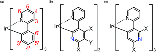 | ||
| Fig. 1 Geometrical structures of substituted fac-Ir(ppy)3, fac-Ir(2,3′-bpy)3, and fac-Ir(2,5′-bpy)3 (see Table S1†). X = H, F, NH2, or OH. Y = H, CN, or NO2. Note that the atom numbering for the ppy ligands is maintained after the replacement of a methane group by a nitrogen atom for simplicity. | ||
| Complex | DFT | MCSCF | +SOCIb | +SOCc | Ref. |
|---|---|---|---|---|---|
| a The positive values indicate that the fac isomer is lower than the corresponding mer isomer.b The MCSCF calculation followed by the SOCI calculation.c The MCSCF calculation followed by the SOCI and SOC calculations. | |||||
| Ir(ppy)3 | 6.4 | 6.1 | 6.0 | 5.7 | 58 |
| Ir(1,3-pdz)3 | 6.0 | 8.5 | 6.9 | 6.6 | |
| Ir(1,4-pdz)3 | 6.3 | 5.5 | 5.3 | 5.5 | |
| Ir(1,5-pdz)3 | 7.3 | 6.3 | 6.6 | 6.5 | |
| Ir(1,6-pdz)3 | 10.3 | 10.0 | 10.6 | 10.0 | |
| Ir(2,3′-bpy)3 | 3.6 | 2.3 | 1.3 | 1.4 | |
| Ir(2,4′-bpy)3 | 5.9 | 5.7 | 5.8 | 5.7 | |
| Ir(2,5′-bpy)3 | 7.1 | 6.6 | 6.4 | 6.5 | |
| Ir(2,6′-bpy)3 | 7.3 | 6.9 | 6.9 | 7.1 | |
Methods of calculation
Although geometrical structures of the ground state and the lowest triplet state in the target complexes were optimized by using one of the popular density functional theory (DFT) methods together with the B3LYP functionals,75,76 the multi-configuration self-consistent field (MCSCF) method77 was employed to optimize molecular orbitals since strong configuration mixture occurs among the low-lying triplet states in IrL3 as described in the next section. All of the calculations used one of relativistic effective core potentials, Stevens–Basch–Krauss–Jasien–Cundari (SBKJC) potentials,78–80 and their associated basis sets augmented by one set of f functions for the iridium atom and one set of polarization functions for the other atoms. This basis set is referred to as SBKJC+p in this series of our research projects. Second-order configuration interaction (SOCI) wavefunctions81 were constructed by using the MCSCF-optimized orbitals and were used to calculate the spectral peaks of phosphorescence and their intensities.55–60 SOCI is one of multi-reference singles and doubles configuration interaction (MR-CISD) approaches. All calculations were performed using the GAMESS suite of program codes.82,83Results and discussion
Brief review of the substituent effects
It is known that the transition from the lowest metal-ligand charge-transfer (MLCT) triplet state to the ground state provides effective phosphorescence in OLEDs because of the strong SOC effects originating from iridium atoms. Traditional molecular orbital theories suggest that the phosphorescent energy is roughly proportional to the energy difference between the highest occupied molecular orbital (HOMO) and the lowest unoccupied molecular orbital (LUMO). Since the HOMO and LUMO consist mainly of the iridium's d orbitals and the ligand's π* orbitals, respectively (Fig. 2),59 it can be said that if the energy of the LUMO is lifted by the introduction of substituents to the ligands or by the replacement of the ligands themselves, the phosphorescent spectra can be shifted to the blue region. However, since IrL3 has the identical three ligands, the three lowest unoccupied orbitals are energetically close to each other and, as a result, strong configuration mixture occurs among these triplet states, as well as in the low-lying singlet states. This is the main reason that the MCSCF method, instead of DFT method, is used in the processes of orbital optimization in the series of our research projects.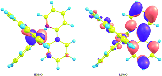 | ||
| Fig. 2 The highest occupied molecular orbital and the lowest unoccupied molecular orbital of fac-Ir(ppy)3. This figure is the same as Fig. 3 in ref. 59, but the value for the isosurface of electron density is 0.03 [e bohr−3]. | ||
Nevertheless, it is true that the energy difference between the HOMO and LUMO is related to that between the lowest triplet state and the ground state and can be used as one of criterions for estimating the spectral shift of phosphorescence, as well as fluorescence. For example, since the fac isomer of Ir(ppy)3 has a geometrical structure largely displaced from C3 symmetry, the degeneracy of the LUMO is broken by the geometrical deformation and the LUMO is energetically somewhat far from the other unoccupied orbitals.58 As a result, the electronic wave function of the lowest triplet state is described mainly by the singly excited configuration from the HOMO to the LUMO. This indicates that the electronic transition between the ground state and the lowest excited triplet state can be approximately described by the single excitation from the HOMO to the LUMO. In fact, as described in our previous paper,59 the spectral shifts calculated by the MCSCF+SOCI+SOC method were explained by the energetic shifts of the HOMO and LUMO when appropriate substituents were introduced into each ppy ligand (Fig. 3). It can be summarized briefly as follows: when a substituent has lone-pair electrons such as fluorine, amino, and hydroxy substituents, the introduction of these substituents to the 4′ and/or 6′ sites in the benzene ring of the ppy ligands (Fig. 1(a)) induces a large blue shift of phosphorescence because of energetic lifting of the LUMO by the substituents (Fig. 3(a)). When a substituent has low-lying π* orbitals such as cyano and nitro substituents, the introduction of these substituents to the 5′ site induces a strong blue shift of phosphorescence because of energetic lowering of the HOMO by the substituents (Fig. 3(b)). Note that the most important point is the fact that the orbital coefficients in the LUMO at the 5′ site of the complex are very small as shown in Fig. 2;59 otherwise the strong π conjugation between the ligands and substituents makes the LUMO lower in energy. In the following sections, the effects of replacement of a methine group by a nitrogen atom on the phosphorescent peaks in Ir(ppy)3 are discussed on the basis of the above considerations by using such sophisticated theoretical methods.
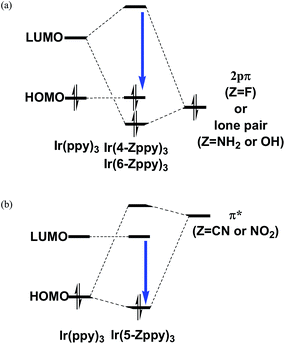 | ||
| Fig. 3 Schematic diagrams of the orbital interaction between a ppy ligand and a substituent in the facial (fac) isomer of IrL3 (L = ligand). Also see Fig. 4 in ref. 59. | ||
Another important factor for estimating the spectral peaks and their intensities of phosphorescence is the magnitude of the geometrical displacement between the lowest triplet state and the ground state. As discussed in our previous paper,59 a large displacement (ΔQS0−T1 = 0.1611 Å; see Table 2) in the mer isomer of Ir(ppy)3 should be one of the reasons why dark phosphorescence has been obtained for this isomer. The displacements in other complexes investigated in our previous study were smaller and were expected to have negligible effects on their phosphorescence. Fortunately, small geometrical displacements have also been obtained between the lowest triplet states and the ground states in the present complexes, where the amino substituents are somewhat largely rotated in Ir(4′,6′-dNH2-2,3′-bpy)3 and Ir(4′,6′-dNH2-5′-CN-2,3′-bpy)3 (Table 2 and S1; see the following discussion†), and therefore no discussion of the geometrical displacements will appear in the following sections.
| Complexa | ΔQS0−T1b (Å) | λc (nm) | Principal contributiond | Wavelengthc (nm) | TDM (e bohr) | T1 (%) | Singlets (%) | HOMOe | LUMOe | λTDDFTf (nm) | Expt.g (nm) | Ref. |
|---|---|---|---|---|---|---|---|---|---|---|---|---|
| a The facial isomers were used except for Ir(ppy)3.b Averaged displacement of all atoms. See ref. 58.c Spectral peaks were calculated with the assumption of Lorentzian widths for all electronic transitions between the spin-mixed (SM) states. The values in parentheses are magnitudes of the spectral shifts when the peak wavelength in the parent complex 1 is taken as the origin. The negative and positive values indicate spectral shifts to blue and red regions, respectively.d Transition from this state to the ground state SM0. “SM3” and “SM4” indicate the third and fourth excited SM states.e The eigenvalues (hartree) obtained by the diagonalization of standard MCSCF Fock matrices. Although the words, HOMO and LUMO, are not appropriate in MCSCF calculations, those are used for simplicity of understanding (see ref. 59).f Time-dependent (TD) DFT calculations using the B3LYP functionals and the SBKJC+p basis sets at the geometries optimized for the lowest triplet state.g Temperature is shown in parenthesis. RT, DFT, and Dev indicate room temperature, the B3LYP/CEP-31G results (ref. 84), and the value measured as a device (ref. 84), respectively.h The DFT calculation was performed for dimethyl-amino substituents (ref. 84).i The DFT calculation was performed for methoxy substituents (ref. 84).j Only (π,π*) excited states are obtained as low-lying excited states. | ||||||||||||
| fac-Ir(ppy)3 | 0.0557 | 491 (0) | SM3 | 501 | 0.299 | 13 | 43 | −0.3409 | 0.0246 | 615 | 58 | |
| SM4 | 491 | 0.890 | 55 | 17 | 510 (298 K) | 6 | ||||||
| 517 (298 K) | 7 | |||||||||||
| 509 (RT) | 9 | |||||||||||
| 515 (RT) | 15 | |||||||||||
| 494 (77 K) | 42 | |||||||||||
| mer-Ir(ppy)3 | 0.1611 | 530 (+39) | SM3 | 530 | 0.255 | 75 | 14 | −0.3080 | 0.0243 | 698 | 58 | |
| 511 (+20) | SM4 | 512 | 1.156 | 9 | 66 | 512 (298 K) | 6 | |||||
| Ir(1,3-pdz)3 | 0.0837 | 522 (+31) | SM3 | 522 | 0.369 | 19 | 41 | −0.3538 | 0.0181 | 599 | ||
| 509 (+18) | SM4 | 509 | 0.708 | 43 | 20 | |||||||
| Ir(1,4-pdz)3 | 0.0778 | 506 (+15) | SM4 | 506 | 1.039 | 57 | 16 | −0.3603 | −0.0008 | 657 | ||
| Ir(1,5-pdz)3 | 0.0669 | 508 (+17) | SM3 | 509 | 0.273 | 30 | 36 | −0.3597 | 0.0069 | 588 | ||
| 494 (+3) | SM4 | 493 | 0.970 | 34 | 24 | |||||||
| Ir(1,6-pdz)3 | 0.0877 | 564 (+73) | SM3 | 564 | 0.115 | 55 | 25 | −0.3349 | 0.0206 | 648 | ||
| 529 (+38) | SM4 | 529 | 1.363 | 19 | 35 | |||||||
| Ir(2,3′-bpy)3 | 0.0719 | 475 (−16) | SM4 | 474 | 0.802 | 52 | 19 | −0.3490 | 0.0256 | 505 | 495 (DFT) | 84 |
| Ir(2,4′-bpy)3 | 0.0774 | 537 (+46) | SM3 | 537 | 0.334 | 37 | 33 | −0.3504 | 0.0041 | 511 | ||
| Ir(2,5′-bpy)3 | 0.0375 | 518 (+27) | SM4 | 518 | 0.940 | 31 | 25 | −0.3709 | 0.0089 | 466 | 462 (DFT) | 84 |
| 448 (−43) | SM4 | 448 | 0.857 | 64 | 13 | 496 (Dev) | 84 | |||||
| Ir(2,6′-bpy)3 | 0.0430 | 511 (+20) | SM3 | 512 | 0.340 | 27 | 36 | −0.3529 | 0.0113 | 493 | ||
| 499 (+8) | SM4 | 498 | 0.846 | 39 | 22 | |||||||
| Ir(4′,6′-dF-2,5′-bpy)3 | 0.0333 | 396 (−95) | SM4 | 395 | 0.805 | 63 | 13 | −0.4021 | −0.0070 | 447 | 438 (RT) | 16 |
| 430 (77 K) | 84 | |||||||||||
| 437 (RT) | 84 | |||||||||||
| Ir(4′,6′-dNH2-2,5′-bpy)3 | 0.0883 | 399 (−92) | SM4 | 398 | 0.944 | 43 | 20 | −0.3581 | 0.0407 | 491 | 511 (DFT)h | 84 |
| Ir(4′,6′-dOH-2,5′-bpy)3 | 0.0338 | 390 (−101) | SM4 | 389 | 0.881 | 52 | 18 | −0.3696 | 0.0294 | 458 | 464 (DFT)i | 84 |
| Ir(4′,6′-dF-2,3′-bpy)3 | 0.0675 | 404 (−87) | SM4 | 403 | 0.778 | 61 | 14 | −0.3807 | 0.0105 | 588 | ||
| Ir(4′,6′-dNH2-2,3′-bpy)3 | 0.1134 | 415 (−76) | SM4 | 415 | 0.982 | 56 | 17 | −0.3430 | 0.0493 | 592 | ||
| Ir(4′,6′-dOH-2,3′-bpy)3 | 0.0535 | 395 (−96) | SM4 | 395 | 0.821 | 65 | 12 | −0.3599 | 0.0357 | 566 | ||
| Ir(5′-CN-2,3′-bpy)3 | 0.0658 | 446 (−45) | SM4 | 445 | 0.738 | 46 | 22 | −0.3879 | −0.0064 | 637 | ||
| Ir(5′-NO2-2,3′-bpy)3 | 0.0665 | 418 (−73) | SM4 | 416 | 0.728 | 41 | 24 | −0.3967 | −0.0110 | 622 | ||
| Ir(4′,6′-dF-5′-CN-2,3′-bpy)3 | 0.0737 | 374 (−117) | SM4 | 373 | 0.728 | 54 | 17 | −0.4154 | −0.0176 | 584 | ||
| Ir(4′,6′-dF-5′-NO2-2,3′-bpy)3 | 0.0568 | 412 (−79) | SM4 | 412 | 0.234 | 10 | 49 | −0.4326 | −0.0143 | j | ||
| Ir(4′,6′-dNH2-5′-CN-2,3′-bpy)3 | 0.1195 | 390 (−101) | SM4 | 389 | 0.926 | 56 | 17 | −0.3776 | 0.0248 | 576 | ||
| Ir(4′,6′-dOH-5′-CN-2,3′-bpy)3 | 0.0506 | 371 (−120) | SM4 | 370 | 0.746 | 64 | 12 | −0.3951 | 0.0080 | 557 | ||
Introduction of a nitrogen atom into the ppy ligands
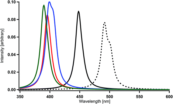
When one of the methine groups in the pyridine ring of each ppy ligand (3, 4, 5, or 6 site shown in the top part of Fig. 1(a)) is replaced by a nitrogen atom [Ir(1,3-pdz)3, Ir(1,4-pdz)3, Ir(1,5-pdz)3, and Ir(1,6-pdz)3 in Table 2 and S1†], the spectral shifts that occur in these four geometrical isomers are discussed in this section. This replacement is equivalent to that of the three ppy ligands by pdz ligands. The most stable isomer among the four isomers is Ir(1,5-pdz)3, while Ir(1,6-pdz)3 is considerably unstable because of N–N bonds in the diazine rings (Table 3). As shown in Table 2 and Fig. 4(a), the spectral peaks λ of phosphorescence in these complexes are shifted to the red region by 3–73 nm. These spectral shifts can be explained by the fact that the replacement results in the energetic lowering of the ligands' orbitals because of the introduction of an electronegative atom “nitrogen” into each ligand. Accordingly, since the LUMO mainly possessing the ligands' π* components is energetically lowered by the replacement and the HOMO mainly possessing the iridium's d components is almost unchanged energetically by the replacement (Fig. 2),59 the energy difference between the HOMO and LUMO becomes smaller and, as a result, the spectral peaks are shifted to the red region as shown in Table 2.| Complexa | DFT | MCSCF | +SOCIb | +SOCc |
|---|---|---|---|---|
| a The facial isomers were used.b The MCSCF calculation followed by the SOCI calculation.c The MCSCF calculation followed by the SOCI and SOC calculations. | ||||
| Ir(1,3-pdz)3 | 10.9 | 9.3 | 9.0 | 9.3 |
| Ir(1,4-pdz)3 | 26.6 | 28.1 | 32.8 | 32.5 |
| Ir(1,5-pdz)3 | 8.0 | 4.9 | 4.4 | 4.9 |
| Ir(1,6-pdz)3 | 74.7 | 82.4 | 87.5 | 88.1 |
| Ir(2,3′-bpy)3 | 18.6 | 21.0 | 20.9 | 21.7 |
| Ir(2,4′-bpy)3 | 14.6 | 15.4 | 16.8 | 16.9 |
| Ir(2,5′-bpy)3 | 6.7 | 3.3 | 4.2 | 4.4 |
| Ir(2,6′-bpy)3 | 0.0 | 0.0 | 0.0 | 0.0 |
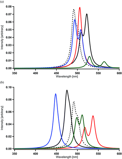 | ||
| Fig. 4 Spectra calculated for Ir complexes at the MCSCF+SOCI+SOC/SBKJC+p level of theory (see Table 2 and S1†). (a) Spectral shifts by the replacement of a methine group of each pyridine ring by a nitrogen atom in Ir(ppy)3. Black (broken) = Ir(ppy)3, black = Ir(1,3-pdz)3, red = Ir(1,4-pdz)3, blue = Ir(1,5-pdz)3, and green = Ir(1,6-pdz)3. (b) Spectral shifts by the replacement of a methine group of each benzene ring by a nitrogen atom in Ir(ppy)3. Black (broken) = Ir(ppy)3, black = Ir(2,3′-bpy)3, red = Ir(2,4′-bpy)3, blue = Ir(2,5′-bpy)3, and green = Ir(2,6′-bpy)3. | ||
On the other hand, when a methine group in the benzene ring of each ppy ligand is replaced by a nitrogen atom or when the ppy ligands are replaced by bpy ligands, a red shift is not always induced as shown in Table 2 and Fig. 4(b) [Ir(2,3′-bpy)3, Ir(2,4′-bpy)3, Ir(2,5′-bpy)3, and Ir(2,6′-bpy)3; also see Table 3]. An explicit blue shift of a spectral peak is induced in Ir(2,3′-bpy)3 (X = H, Y = H in Fig. 1(b)) and Ir(2,5′-bpy)3 (X = H in Fig. 1(c)), Ir(2,3′-bpy)3 being the most stable (Table 3). These results are consistent with the DFT calculations and experimental evidences reported previously.84 These suggest that other factors are more effective than energetic lowering of the ligands' orbitals.
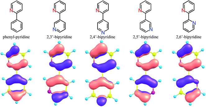
For the purpose of analyzing these results, DFT geometrical optimizations were performed for the four geometrical isomers of bi-pyridine (a hydrogen-terminated ligand; bpy-H), the geometries of which were assumed to be planar. These isomers correspond to four kinds of replacements of a methine group at the 3′, 4′, 5′, and 6′ sites of a benzene ring in phenyl-pyridine (a hydrogen- terminated ligand; ppy-H), respectively (See the sites shown in the bottom part of Fig. 1(a)). In Fig. 5, it is assumed that the top pyridine ring corresponds to that of the ppy ligand and the bottom ring is provided by the replacement of a methine group in a benzene ring of the ppy ligand by a nitrogen atom. The HOMO in ppy-H is also shown in this figure for comparison. In Ir(2,3′-bpy)3, Ir(2,4′-bpy)3, Ir(2,5′-bpy)3, and Ir(2,6′-bpy)3, since a covalent bond is formed between the iridium atom and the 2′ site of the bottom pyridine ring (a benzene ring in Ir(ppy)3), the electron densities at the 2′ site must provide stronger effects when a complex is formed. As shown in Fig. 5, it is natural that the π density distribution is almost the same in the top pyridine rings of the four isomers as that in ppy-H, but a different distribution was obtained in the bottom rings of the four isomers, since a different methine group is replaced by a nitrogen atom. In the following discussion, the atom numbering for the ppy ligand is maintained after the replacement of a methane group by a nitrogen atom for simplicity. Then, it is easily found that the density at the 2′ site in 2,5′-bipyridine is less than half of those in the others and even smaller than that in ppy-H. This result indicates that when a complex is formed, the π-electron donation from ligands to the iridium atom in Ir(2,5′-bpy)3 should be explicitly weaker than that in the other isomers and even weaker than that in the parent complex Ir(ppy)3. As a result, the iridium's d orbitals are rarely pushed up energetically by ligands' π orbitals in Ir(2,5′-bpy)3, and the HOMO of Ir(2,5′-bpy)3 shown in Fig. 6(b) is thus lower in energy than those in the others shown in Fig. 6(c) and even lower than that in ppy-H shown in Fig. 6(a). This must be the reason why an energetically higher (d−π*) triplet state is obtained and a relatively large spectral shift of phosphorescence to the blue region is obtained in Ir(2,5′-bpy)3 in comparison with that in the parent complex Ir(ppy)3.
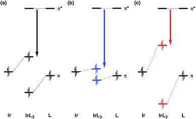 | ||
| Fig. 6 Schematic diagram of the orbital interaction between an iridium atom and the four isomers of bipyridine shown in Fig. 5. (a) Forming a covalent bond between the iridium atom and the 2′ carbon atom of the ligand in fac-Ir(ppy)3. (b) Forming a bond weaker than (a). (c) Forming a bond stronger than (a). | ||
As shown in Fig. 5, although the π electron density of the HOMO is relatively large at the 2′ site in 2,3′-bipyridine, a spectral shift to the blue region was also obtained in Ir(2,3′-bpy)3 as shown in Table 2 and Fig. 4(b). This result can be explained by the fact that a stronger electronegative atom “nitrogen” is introduced to the next site of the C–Ir covalent bond. In other words, the ligands' π electrons are withdrawn by not only the iridium atom but also the neighboring nitrogen atom. As a result, it can be said that the same effects appear in Ir(2,3′-bpy)3 as described in the previous paragraph and shown in Fig. 6(b).
In order to confirm the above discussion, the components of the low-lying excited states in Ir(2,3′-bpy)3, Ir(2,4′-bpy)3, Ir(2,5′-bpy)3, and Ir(2,6′-bpy)3 were calculated and analyzed, and the results are shown in the columns “T1” and “singlets” in Table 2, where the values in the column “T1” are the percent weights of the lowest triplet state “T1” in the third or fourth excited spin-mixed state, denoted by SM3 or SM4, obtained after inclusion of the SOC effects, and the values in the column “singlets” are the percent weights of all singlet states in the SM3 or SM4 state. The largest contribution to the emission in these complexes is the transition from the SM3 or SM4 state to the SM0 state. The largest component in the SM3 and SM4 states is always T1, and the main electron configuration of T1 is given by the single excitation from the HOMO to LUMO, which must be the reason why the discussion based on one-electron approximation is reasonable as stated above. However, the weight of T1 is not always explicitly large as shown in the column “T1” of Table 2. This is caused by strong SOC mixing among the low-lying triplet states and excited singlet states in these complexes. Even though one-electron approximation is applicable to such considerations, these results suggest that the discussion based on one-electron approximation sometimes needs to be examined by using some advanced theoretical methods.
Substituent effects in Ir(2,3′-bpy)3 and Ir(2,5′-bpy)3
In our recent investigations,55–60 the difference between calculated and observed peaks of phosphorescence was found to be 24–29 nm [14 nm in Ir(ppy)3]. When the available experimental data for Ir(ppy)3,9 Ir(4′,6′-dF-ppy)3,9 and Ir(5′-CN-4′,6′-dF-ppy)3![[thin space (1/6-em)]](https://www.rsc.org/images/entities/char_2009.gif) 13 (see Table S1†) are compared with our calculated results, a more reliable estimated value λest (nm) for such kinds of iridium complexes can be proposed for the spectral peaks by using the following equation:
13 (see Table S1†) are compared with our calculated results, a more reliable estimated value λest (nm) for such kinds of iridium complexes can be proposed for the spectral peaks by using the following equation:| λest = 0.785 × λ + 120, | (1) |
where λ (nm) in the right-hand side is the calculated spectral peak shown in Table 2. When this equation is applied to the calculated results, Ir(2,5′-bpy)3 (X = H in Fig. 1(c)) is estimated to have a phosphorescent peak at the wavelength of 472 nm and its phosphorescence is not deep blue. In fact, the spectral peak at the wavelength of 496 nm was observed when Ir(2,5′-bpy)3 was doped into the emissive layer of OLEDs.84 Therefore, it is necessary to combine the effects caused by the replacement of a methine group by a nitrogen atom with the substituent effects in order to design materials for deep blue phosphorescence. Since these induce spectral shifts to the blue region in comparison with the parent complex Ir(ppy)3 as discussed above, the discussion in this section is focused on the substituent effects in Ir(2,3′-bpy)3 (X = H and Y = H in Fig. 1(b)) and Ir(2,5′-bpy)3 (X = H in Fig. 1(c)).
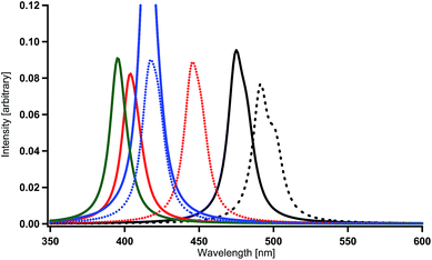
The LUMO in Ir(2,5′-bpy)3 is very similar to that in the parent complex Ir(ppy)3 (Fig. 2). Namely, the coefficients at the 4′ and 6′ sites are relatively large, so that the introduction of fluorine, amino, or hydroxy substituents to these sites is expected to induce a large shift of the phosphorescent peak to the blue region, on the basis of the discussion in our previous investigations.59 In fact, the present calculations provide spectral shifts of 92–101 nm to the blue region in Ir(4′,6′-dF-2,5′-bpy)3 (X = F in Fig. 1(c)), Ir(4′,6′-dNH2-2,5′-bpy)3 (X = NH2 in Fig. 1(c)), and Ir(4′,6′-dOH-2,5′-bpy)3 (X = OH in Fig. 1(c)) as shown in Table 2 and Fig. 7. By using eqn. (1), the phosphorescent peaks are estimated to appear at the wavelengths of 431 nm in Ir(4′,6′-dF-2,5′-bpy)3, 433 nm in Ir(4′,6′-dNH2-2,5′-bpy)3, and 426 nm in Ir(4′,6′-dOH-2,5′-bpy)3. These results are supported by the experimental observations that the emission maximum of Ir(4′,6′-dF-2,5′-bpy)3 appears at the wavelength of 438 nm (room temperature),16 430 nm (77 K),84 and 437 nm (room temperature).84
Now, it is experimentally suggested that the amino and hydroxy substituents are inappropriate in functional materials because of easy donation or acceptance of a hydrogen atom or ion.85 In the present investigation, the differences between the effects of the amino and dimethyl-amino substituents and between hydroxy and methoxy substituents were investigated first (Table 4). The spectral shift to the blue region by the introduction of a dimethyl-amino substituent to the 4′ or 6′ site of Ir(ppy)3 (Fig. 1(a)) is calculated to be only 2-nm or 10-nm smaller than that by the introduction of an amino substituent. Similarly, the spectral shift to the blue region by the introduction of a methoxy substituent to the 4′ or 6′ site of Ir(ppy)3 (Fig. 1(a)) is calculated to be only 4-nm or 3-nm smaller than that by the introduction of a hydroxy substituent. Since the largest change (10 nm) can be caused by the steric effect at the crowded 6′ site, it can be understood that almost no difference appears between the complexes possessing amino and hydroxy substituents and those possessing dimethylamino and methoxy substituents. If a broad interpretation is applied to the present discussion, it can be said that a dialkyl-amino (NR2) or alchoxy (OR) substituent (R = alkyl group) can be used for obtaining spectral shifts to the blue region, even though the magnitude of spectral shifts might become slightly smaller. Therefore, the complexes of X = F, NR2, and OR in Fig. 1(c) should be good candidates for blue phosphorescent materials.
| Complex | ΔQS0−T1a (Å) | λ (nm) | Principal contribution | Wavelength (nm) | TDM (e bohr) |
|---|---|---|---|---|---|
| a See the footnote in Table 2.b The terminal methyl groups of dimethyl amino groups are rotated by the steric effect at the crowded 6′ site (see the text). | |||||
| Ir(4′-NH2-ppy)3 | 0.0318 | 442 | SM4 | 442 | 0.934 |
| Ir(4′-NMe2-ppy)3 | 0.0517 | 444 (+2) | SM4 | 444 | 0.979 |
| Ir(6′-NH2-ppy)3 | 0.0618 | 482 | SM4 | 482 | 0.974 |
| SM2 | 497 | 0.120 | |||
| Ir(6′-NMe2-ppy)3 | 0.2445b | 492 (+10) | SM4 | 492 | 0.951 |
| SM2 | 506 | 0.168 | |||
| Ir(4′-OH-ppy)3 | 0.0289 | 438 | SM4 | 438 | 0.899 |
| SM3 | 444 | 0.171 | |||
| Ir(4′-OMe-ppy)3 | 0.0425 | 443 (+5) | SM4 | 442 | 0.902 |
| SM3 | 449 | 0.220 | |||
| Ir(6′-OH-ppy)3 | 0.0687 | 469 | SM4 | 469 | 0.900 |
| SM3 | 477 | 0.247 | |||
| Ir(6′-OMe-ppy)3 | 0.0711 | 472 (+3) | SM4 | 472 | 0.903 |
| SM3 | 480 | 0.251 | |||
Likewise, the LUMO in Ir(2,3′-bpy)3 (X = H and Y = H in Fig. 1(b)) is very similar to that in the parent complex Ir(ppy)3 (Fig. 2). Namely, a large spectral shift to the blue region can be obtained when X = F, NH2, or OH and Y = H in Fig. 1(b). The wavelengths of the spectral peaks calculated for Ir(4′,6′-dF-2,3′-bpy)3 (X = F and Y = H), Ir(4′,6′-dNH2-2,3′-bpy)3 (X = NH2 and Y = H), and Ir(4′,6′-dOH-2,3′-bpy)3 (X = OH and Y = H) are shown in Table 2 and Fig. 8, and they need to be corrected to 437 nm in Ir(4′,6′-dF-2,3′-bpy)3, 446 nm in Ir(4′,6′-dNH2-2,3′-bpy)3, and 430 nm in Ir(4′,6′-dOH-2,3′-bpy)3 by using eqn. (1). As described in the previous paragraph, since negligible changes are expected to be obtained by using dialkyl-amino or alchoxy substituents instead of amino or hydroxy substituents, it can be said that the complexes of X = F, NR2, and OR, together with Y = H, in Fig. 1(b) are also good candidates for blue phosphorescent materials.
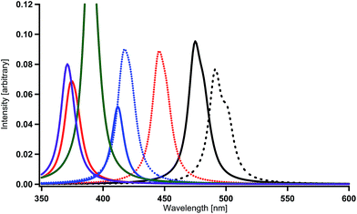
A substituent cannot be introduced to the 5′ sites in Ir(2,5′-bpy)3 (Fig. 1(c)), but it can be introduced to the 5′ sites in Ir(2,3′-bpy)3 (Fig. 1(b)). Even though the magnitude of spectral shift in Ir(2,3′-bpy)3 is smaller than that in Ir(2,5′-bpy)3 in comparison with Ir(ppy)3, remarkable shifts to the blue region are expected when appropriate substituents are introduced into appropriate sites of the ligands. According to the discussion in our previous paper,59 spectral shifts to the blue region can be obtained by the introduction of an electron-donating substituent, such as a cyano or nitro substituent, into the 5′ site in each bpy ligand (Fig. 1(b)). The calculated results shown in Table 2 and Fig. 8 are consistent with our discussion. By using eqn. (1), the peaks are estimated to appear at the wavelengths of 470 nm in Ir(5′-CN-2,3′-bpy)3 (X = H and Y = CN) and 448 nm in Ir(5′-NO2-2,3′-bpy)3 (X = H and Y = NO2). As discussed in our previous paper,59 the reason why such results are obtained is that the low-lying π* orbitals of the substituents effectively interact with the iridium's d orbitals and make the HOMO lower in energy in the complexes. Although the magnitudes of these spectral shifts are not so large as those of Ir(2,5′-bpy)3, the present discussion and consideration are proved to be reasonable.
Finally, as performed in our previous study, the combination effects of the substituents in Ir(2,3′-bpy)3 were examined in order to obtain deep blue-color phosphorescence. The present calculations for Ir(4′,6′-dF-5′-CN-2,3′-bpy)3 (X = F and Y = CN) and Ir(4′,6′-dF-5′-NO2-2,3′-bpy)3 (X = F and Y = NO2) provide spectral shifts of 117 nm and 79 nm to the blue region when the spectral peaks are compared with that in Ir(ppy)3 (Table 2 and Fig. 9). The sum of the magnitudes of spectral shifts to the blue region induced by the introductions of fluorine substituents (87 nm for Ir(4′,6′-dF-2,3′-bpy)3) and a cyano substituent (45 nm for Ir(5′-CN-2,3′-bpy)3) is comparable with that for obtained for Ir(4′,6′-dF-5′-CN-2,3′-bpy)3 (see Table 2). This seems to be simply caused by the linear structure of the cyano substituent and by the weak interaction among the substituents. Similarly, large spectral shifts of 101 nm and 120 nm to the blue region obtained for Ir(4′,6′-dNH2-5′-CN-2,3′-bpy)3 (X = NH2 and Y = CN) and Ir(4′,6′-dOH-5′-CN-2,3′-bpy)3 (X = OH and Y = CN) as shown in Table 2 and Fig. 9 are comparable with the sums of the magnitudes of spectral shifts obtained for Ir(4′,6′-dNH2-2,3′-bpy)3 and Ir(5′-CN-2,3′-bpy)3 (76 + 45 = 121 nm) and for Ir(4′,6′-dOH-2,3′-bpy)3 and Ir(5′-CN-2,3′-bpy)3 (96 + 45 = 141 nm). Accordingly, it can be concluded that the complexes of X = F, NR2, or OR, together with Y = CN, are good candidates for blue phosphorescent materials.
The spectral shifts (79 nm) obtained for Ir(4′,6′-dF-5′-NO2-2,3′-bpy)3 is remarkably smaller than the sum of the magnitudes of spectral shifts obtained for Ir(4′,6′-dF-2,3′-bpy)3 and Ir(5′-NO2-2,3′-bpy)3 (87 + 83 = 160 nm). This is consistent with the results reported in our previous investigation;59 the combination of the nitro substituent with electron-donating substituents makes the spectral shifts smaller because of strong electrostatic and steric interactions among neighboring substituents. Such strong interaction sometimes derives strange geometrical structures for the lowest triplet states. In fact, when the combination of X = NH2 or OH and Y = NO2 was used, the geometry optimizations for the lowest triplet states derive a new bond between a terminal oxygen atom of the nitro substituents and the closest hydrogen atom of the amino or hydroxy substituents. These results suggest that such complexes could be broken when they are promoted to the lowest triplet state by the electric field and should not be used as functional materials. As described above, if X = NR2 or X = OR instead of X = NH2 or X = OH, such new bonds may not be created in the lowest triplet states and effective spectral shifts to the blue region could be obtained even though the magnitudes of spectral shifts may be small. Since the nitro substituent could get hydrogen atoms or ions from host molecules in the emissive layers of OLEDs, the OLEDs created by such materials may have very short lifetime.
Summary
In the present investigation, MCSCF+SOCI+SOC/SBKJC+p calculations were performed in order to examine the effects of replacement of a methine group in each ppy ligand of fac-Ir(ppy)3 by a nitrogen atom for the purpose of obtaining deep blue phosphorescence. Only the replacements of methine groups at the 3′ and 5′ sites of each ppy ligand by nitrogen atoms were calculated to induce a spectral shift to the blue region. These results can be explained by the strong electronegativity of nitrogen atoms and by the magnitude of the electron density at the 2′ carbon atom of the ppy or bpy ligands. Subsequently, the substituent effects in fac-Ir(bpy)3 were investigated and found to be similar to those in fac-Ir(ppy)3 reported in our previous paper.59 Based on systematic calculations and theoretical consideration, the most effective modification for deep blue phosphorescence should be the introduction of a nitrogen atom into the 3′ or/and 5′ site of benzene rings of the ppy ligands in fac-Ir(ppy)3 together with the combination of the substituents X = F, NR2, or OR (R = alkyl group) and Y = CN or NO2 (see Fig. 1). The same investigations when an ancillary ligand such as a picolinate (pic) or acetylacetonate (acac) ligand is introduced into fac-Ir(ppy)3 are in progress.References
- C. W. Tang, S. W. Van Slyke and C. H. Chen, J. Appl. Phys., 1989, 65, 3610–3616 CrossRef CAS.
- M. A. Baldo, S. Lamansky, P. E. Burrows, M. E. Thompson and S. R. Forrest, Appl. Phys. Lett., 1999, 75, 4–6 CrossRef CAS.
- C. Adachi, M. A. Baldo and S. R. Forrest, Appl. Phys. Lett., 2000, 77, 904–906 CrossRef CAS.
- K. Pierloot, A. Ceulemans, M. Merchán and L. Serrano-Andrés, J. Phys. Chem. A, 2000, 104, 4374–4382 CrossRef CAS.
- J. Brooks, Y. Babayan, S. Lamansky, P. I. Djurovich, I. Tsybam, R. Bau and M. E. Thompson, Inorg. Chem., 2002, 41, 3055–3066 CrossRef CAS PubMed.
- A. B. Tamayo, B. D. Alleyne, P. I. Djurovich, S. Lamansky, I. Tsyba, N. N. Ho, R. Bau and M. E. Thompson, J. Am. Chem. Soc., 2003, 125, 7377–7387 CrossRef CAS PubMed.
- A. Beeby, S. Bettington, I. D. Samuel and Z. Wang, J. Mater. Chem., 2003, 13, 80–83 RSC.
- Y. Kawamura, K. Goushi, J. Brooks, J. J. Brown, H. Sasabe and C. Adachi, Appl. Phys. Lett., 2005, 86, 071104 CrossRef.
- K. Dedeian, J. Shi, N. Shepherd, E. Forsythe and D. C. Morton, Inorg. Chem., 2005, 44, 4445–4447 CrossRef CAS PubMed.
- R. Ragni, E. A. Plummer, K. Brunner, J. W. Hofstraat, F. Babudri, G. M. Farinola, F. Naso and L. de Cola, J. Mater. Chem., 2006, 16, 1161–1170 RSC.
- X. Y. Cai, A. B. Padmaperuma, L. S. Sapochak, P. A. Vecchi and P. E. Burrows, Appl. Phys. Lett., 2008, 92, 083308 CrossRef.
- X. Gu, T. Fei, H. Zhang, H. Xu, B. Yang, Y. Ma and X. Liu, J. Phys. Chem., 2008, 112, 8387–8393 CrossRef CAS PubMed.
- S. H. Kim, J. Jang, S. J. Lee and J. Y. Lee, Thin Solid Films, 2008, 517, 722–726 CrossRef CAS.
- S. Reineke, F. Lindner, G. Schwartz, N. Seidler, K. Walzer, B. Lüssem and K. Leo, Nature, 2009, 459, 234–238 CrossRef CAS PubMed.
- H. Wang, Q. Liao, H. Fu, Y. Zeng, Z. Jiang, J. Ma and J. Yao, J. Mater. Chem., 2009, 19, 89–96 RSC.
- S. J. Lee, K.-M. Park, K. Yang and Y. Kang, Inorg. Chem., 2009, 48, 1030–1037 CrossRef CAS PubMed.
- X. Li, Z. Wu, X. Li, H. Zhang and X. Liu, J. Comput. Chem., 2011, 32, 1033–1042 CrossRef CAS PubMed.
- J. Wang, B. Xia, F. Bai, L. Sun and H. Zhang, Int. J. Quantum Chem., 2011, 111, 4080–4090 CrossRef CAS.
- A. Kadari, A. Moncomble, I. Ciofini, M. Brahimi and C. Adamo, J. Phys. Chem. A, 2011, 115, 11861–11865 CrossRef CAS PubMed.
- Y. Hisamatsu and S. Aoki, Eur. J. Inorg. Chem., 2011, 5360–5369 CrossRef CAS.
- E. Baranoff, B. F. E. Curchod, J. Frey, R. Scopelliti, F. Kessler, I. Tavernelli, U. Rothlisberger, M. Grätzel and M. K. Nazeeruddin, Inorg. Chem., 2012, 51, 215–224 CrossRef CAS PubMed.
- Y. Su and L. Kang, Int. J. Quantum Chem., 2012, 112, 2422–2428 CrossRef CAS.
- J. Su, X. Sun, G. Gahungu, X. Qu, Y. Liu and Z. Wu, Synth. Met., 2012, 162, 1392–1399 CrossRef CAS.
- Q. Cao, J. Wang, Z. Tian, Z. Wie and F. Bai, J. Comput. Chem., 2012, 33, 1038–1046 CrossRef CAS PubMed.
- H. Li, P. Winget, C. Risko, J. S. Sears and J. Bredas, Phys. Chem. Chem. Phys., 2013, 15, 6293–6302 RSC.
- D. Han, G. Zhang, H. Cai, X. Zhang and L. Zhao, J. Lumin., 2013, 138, 223–228 CrossRef CAS.
- X. Shang, D. Han, D. Li and Z. Wu, Chem. Phys. Lett., 2013, 565, 12–17 CrossRef CAS.
- X. Shang, Y. Liu, X. Qui and Z. Wu, J. Lumin., 2013, 143, 402–408 CrossRef CAS.
- X. Shang, D. Han, D. Li, S. Guan and Z. Wu, Chem. Phys. Lett., 2013, 588, 68–75 CrossRef CAS.
- Y. Si, Y. Liu, X. Qu, Y. Wang and Z. Wu, Dalton Trans., 2013, 42, 14149–14157 RSC.
- J. M. Younker and K. D. Dobbs, J. Phys. Chem. C, 2013, 117, 25714–25723 CAS.
- R. Srivastava, Y. Kada and B. Kotamarthi, Comput. Theor. Chem., 2013, 1009, 35–42 CrossRef CAS.
- X. Qu, Y. Liu, G. Godefroid, Y. Si, X. Shang, X. Wu and Z. Wu, Eur. J. Inorg. Chem., 2013, 3370–3383 CrossRef CAS.
- M. Song, Z. Hao, Z. Wu, S. Song, I. Zhou, R. Deng and H. Zhang, J. Phys. Org. Chem., 2013, 26, 840–848 CrossRef CAS.
- X. Shang, Y. Liu, J. Su, G. Gahungu, X. Qu and Z. Wu, Int. J. Quantum Chem., 2014, 114, 183–191 CrossRef CAS.
- Y. Si, X. Sun, Y. Liu, X. Qu, Y. Wang and Z. Wu, Dalton Trans., 2014, 43, 714–721 RSC.
- X. Qu, Y. Liu, Y. Si, X. Wu and Z. Wu, Dalton Trans., 2014, 43, 1246–1260 RSC.
- Y. Li, L.-Y. Zou, A.-M. Ren, M.-S. Ma and J.-X. Fan, Chem.– Eur. J., 2014, 20, 4671–4680 CrossRef CAS PubMed.
- D. Han, C. Li, L. Zhao, X. Sun and G. Zhang, Chem. Phys. Lett., 2014, 595–596, 260–265 CrossRef CAS.
- K. Mori, T. P. M. Goumans, E. Lenthe and F. Wang, Phys. Chem. Chem. Phys., 2014, 16, 14523–14530 RSC.
- L. Wang, Y. Wu, G. Shan, Y. Geng, J. Zhang, D. Wang, G. Yang and Z. Su, J. Mater. Chem. C, 2014, 2, 2859–2868 RSC.
- J. Frey, B. F. E. Curchod, R. Scopelliti, I. Tavernelli, U. Rothlisberger, M. K. Nazeeruddin and E. Baranoff, Dalton Trans., 2014, 43, 5667–5679 RSC.
- B. F. Minaev, S. Knuts, H. Agren and O. Vahtras, Chem. Phys., 1993, 175, 245–254 CrossRef CAS.
- H. Agren, O. Vahtras and B. F. Minaev, Adv. Quantum Chem., 1996, 27, 71–162 CrossRef.
- B. F. Minaev, Opt. Spectrosc., 2005, 98(3), 336–340 CrossRef CAS.
- B. F. Minaev, E. Jansson, H. Ågrena and S. Schrader, J. Chem. Phys., 2006, 125, 234704 CrossRef PubMed.
- E. Jansson, B. Minaev, S. Schrader and H. Ågren, Chem. Phys., 2007, 333, 157–167 CrossRef CAS.
- B. Minaev, V. Minaeva and H. Ågren, J. Phys. Chem. A, 2009, 113, 726–735 CrossRef CAS PubMed.
- B. Minaev, H. Ågren and F. de Angelis, Chem. Phys., 2009, 358, 245–257 CrossRef CAS.
- X. Li, B. Minaev, H. Ågren and H. Tian, J. Phys. Chem. C, 2011, 115, 20724–20731 CAS.
- X. Li, B. Minaev, H. Ågren and H. Tian, Eur. J. Inorg. Chem., 2011, 2517–2524 CrossRef CAS.
- D. Volyniuk, V. Cherpak, P. Stakhira, B. F. Minaev, G. V. Baryshnikov, M. Chapran, A. Tomkeviciene, J. Keruckas and J. V. Grazulevicius, J. Phys. Chem. C, 2013, 117, 22538–22544 CAS.
- B. F. Minaev, G. Baryshnikov and H. Agren, Phys. Chem. Chem. Phys., 2013, 16, 1719–1758 RSC.
- V. Cherpak, P. Stakhira, B. Minaev, G. Baryshnikov, E. Stromylo, I. Helzhynskyy, M. Chapran, D. Volyniuk, D. Tomkuté-Lukšiené, T. Malinauskas, V. Getautis, A. Tomkeviciene, J. Simokaitiene and J. V. Grazulevicius, J. Phys. Chem. C, 2014, 118, 11271–11278 CAS.
- T. Matsushita, T. Asada and S. Koseki, J. Phys. Chem. A, 2006, 110, 13295–13302 CrossRef CAS PubMed.
- S. Koseki, Y. Kagita, S. Matsumoto, T. Asada, S. Yagi, H. Nakazumi and T. Matsushita, J. Phys. Chem. C, 2014, 118, 15412–15421 CAS.
- T. Matsushita, T. Asada and S. Koseki, J. Phys. Chem. C, 2007, 111, 6897–6903 CAS.
- S. Koseki, N. Kamata, T. Asada, S. Yagi, H. Nakazumi and T. Matsushita, J. Phys. Chem. C, 2013, 117, 5314–5327 CAS.
- S. Koseki, H. Yoshinaga, T. Asada and T. Matsushita, RSC Adv., 2015, 5, 35760–35772 RSC.
- S. Ikawa, S. Yagi, T. Maeda, H. Nakazumi, H. Fujiwara, S. Koseki and Y. Sakurai, Inorg. Chem. Commun., 2013, 38, 14–19 CrossRef CAS.
- S. Koseki, M. S. Gordon, M. W. Schmidt and N. Matsunaga, J. Phys. Chem., 1995, 99, 12764–12772 CrossRef CAS.
- S. Koseki, M. W. Schmidt and M. S. Gordon, J. Phys. Chem. A, 1998, 102, 10430–10435 CrossRef CAS.
- S. Koseki, D. G. Fedorov, M. W. Schmidt and M. S. Gordon, J. Phys. Chem. A, 2001, 105, 8262–8268 CrossRef CAS.
- S. Koseki, M. W. Schmidt and M. S. Gordon, J. Phys. Chem., 1992, 96, 10768–10772 CrossRef CAS.
- N. Matsunaga, S. Koseki and M. S. Gordon, J. Chem. Phys., 1996, 104, 7988–7996 CrossRef CAS.
- S. Koseki, Y. Ishihara, U. Umeda, D. G. Fedorov and M. S. Gordon, J. Phys. Chem. A, 2002, 106, 785–794 CrossRef CAS.
- S. Koseki, Y. Ishihara, H. Umeda, D. G. Fedorov, M. W. Schmidt and M. S. Gordon, J. Phys. Chem. A, 2004, 108, 4707–4719 CrossRef CAS.
- S. Koseki, T. Matsushita and M. S. Gordon, J. Phys. Chem. A, 2006, 110, 2560–2570 CrossRef CAS PubMed.
- S. Koseki, Computational Methods in Sciences and Engineering, Theory and Computation: Old Problems and New Challenges, ed. G. Maroulis and T. Simos, AIP, New York, 2008, CP963, Vol. 1, pp. 257–267 Search PubMed.
- S. Koseki, N. Shimakura, Y. Fujimura, T. Asada and H. Kono, J. Chem. Phys., 2009, 131, 044122 CrossRef PubMed.
- T. Hisashima, T. Matsushita, T. Asada and S. Koseki, Theor. Chem. Acc., 2008, 120, 85–94 CrossRef CAS.
- S. Koseki, T. Hisashima, T. Asada, A. Toyota and N. Matsunaga, J. Chem. Phys., 2010, 133, 174112 CrossRef PubMed.
- D. G. Fedorov, S. Koseki, M. W. Schmidt and M. S. Gordon, Int. Rev. Phys. Chem., 2003, 22, 551–592 CrossRef CAS.
- D. G. Fedorov, M. W. Schmidt, S. Koseki, and M. S. Gordon, Recent Advances in Relativistic Molecular Theory, World Scientific, Singapore, 2004, Vol. 5, pp. 107–136 Search PubMed.
- R. G. Parr and W. Yang, Density-Functional Theory of Atoms and Molecules, Oxford, 1989, pp. 1–333 and references therein Search PubMed.
- A. D. Becke, J. Chem. Phys., 1993, 98, 5648–5652 CrossRef CAS.
- M. W. Schmidt and M. S. Gordon, Annu. Rev. Phys. Chem., 1998, 49, 233–266 CrossRef CAS PubMed.
- W. J. Stevens, H. Basch, M. Krauss and P. Jasien, Can. J. Chem., 1992, 70, 612–630 CrossRef CAS.
- T. R. Cundari and W. J. Stevens, J. Chem. Phys., 1993, 98, 5555–5565 CrossRef CAS.
- Exponents of 0.938 are used for f functions on Ir. The d exponents are 0.800 (C and N). The p exponents are 1.100 (H). This basis set is referred to as SBKJC+p.
- B. H. Lengsfield III, J. A. Jafri, D. H. Phillips and C. W. Bauschlicher Jr, J. Chem. Phys., 1981, 74, 6849–6856 CrossRef.
- M. W. Schmidt, K. K. Baldridge, J. A. Boatz, S. T. Elbert, M. S. Gordon, J. H. Jensen, S. Koseki, N. Matsunaga, K. A. Nguyen, S. Su, T. L. Windus, M. Dupuis and J. A. Montgomery, J. Comput. Chem., 1993, 14, 1347–1363 CrossRef CAS.
- M. S. Gordon and M. W. Schmidt, Advances in electronic structure theory: Gamess a decade later in Theory and Applications of Computational Chemistry: The First Forty Years, ed. C. E. Dykstra, G. Frenking, K. S. Kim and G. E. Scuseria, Elsevier, Amsterdam, 2005 Search PubMed.
- J.-Y. Tsai, G. Kottas, W. Yeager, Z. Elshenawy, C. Xia, G. Szigethy and J. Brooks. Organic electroluminescent materials and devices. U. S. Patent 0 194 612 A1, Jul. 9, 2015.
- For example, R. R. Morrison and R. N. Boyd, Organic Chemistry, Prentice-Hall Inc, 6th edn, 1992 Search PubMed.
Footnote |
| † Electronic supplementary information (ESI) available. See DOI: 10.1039/c6ra07778a |
| This journal is © The Royal Society of Chemistry 2016 |

