A pure organic heterostructure of μ-oxo dimeric iron(III) porphyrin and graphitic-C3N4 for solar H2 roduction from water†
D. H.
Wang
ab,
J. N.
Pan
ab,
H. H.
Li
ab,
J. J.
Liu
ab,
Y. B.
Wang
ab,
L. T.
Kang
*ab and
J. N.
Yao
*c
aKey Laboratory of Design and Assembly of Functional Nanostructures, Chinese Academy of Sciences, Fuzhou, 350002, P.R. China. E-mail: longtiank@fjirsm.ac.cn
bFujian Provincial Key Laboratory of Nanomaterials, Fujian Institute of Research on the Structure of Matter, Chinese Academy of Sciences, Fuzhou, Fujian 350002, P.R. China
cBeijing National Laboratory for Molecular Sciences (BNLMS), Institute of Chemistry, Chinese Academy of Sciences, Beijing 100190, P. R. China. E-mail: jnyao@iccas.ac.cn
First published on 18th November 2015
Abstract
Due to the two-dimensional flexible structure and abundant pendant amine, graphitic-C3N4 (g-C3N4) may be easily modified by organic molecules as a promising photocatalyst for solar H2 production from water. Here, through a simple liquid chemical reaction between g-C3N4 and the precursor of μ-oxo dimeric iron(III) porphyrin [(FeTPP)2O], we provide a novel route to construct a pure organic heterostructure of g-C3N4/(FeTPP)2O on the basis of the π–π and the Fe–amine interactions. The experimental results demonstrated that (FeTPP)2O acted not just as a photosensitizer, but also played the role of a charge promotor to prohibit the recombination of the excited electrons and holes of g-C3N4. As compared to pure or mixed g-C3N4 and/or (FeTPP)2O, the obtained pure organic g-C3N4/(FeTPP)2O heterostructure exhibited dramatic photocatalytic H2 production under solar light without any cocatalysts.
Introduction
The increasing worldwide energy shortage and environmental issues have stimulated intensive research on searching for green technologies as sustainable ways to address these concerns. Among various potential solutions, solar H2 production from water splitting offers an environmentally clean energy for the future and exhibits a method for solar energy storage and chemical energy conversion.1–3 One ideal route for H2 evolution is semiconductor-based water splitting under solar light irradiation.4–7 The most challenging task in photocatalytic water splitting is to develop efficient and stable photocatalysts, which are capable of sufficiently absorbing solar light for splitting water. At present, many semiconductors have been widely studied, mainly including inorganic materials such as metal oxides, metal sulfides and metal nitrides.7–10g-C3N4, a new metal-free polymeric semiconductor,11,12 stands out from a mass of photocatalysts as a shining star due to its appealing electronic structure with a medium band gap for both water reduction and oxidation, and good chemical and physical stability.13 Especially, the polymeric semiconductor is only composed of C and N elements, and can be easily prepared from low-cost and environmentally friendly precursors,14–17 such as urea,15 thiourea16 and melamine.17,18 The adjustable photocatalytic activity in visible light combining with its low cost make it potentially useful in a variety of applications.19 The utilization of g-C3N4 as a photocatalyst for hydrogen evolution has been intensively studied in recent years, nevertheless, the photocatalytic efficiency of pristine g-C3N4 is still not satisfactory due to the rapid recombination of photo-excited electron–hole pairs, low visible utilization efficiency and small surface area.20 To break these limitations, many strategies such as textural managing,22–24 doping,25,26 heterostructure construction,20,27 dye sensitization,28,29etc., have been developed.21–29 Among them, the formation of heterostructures holds great potential to separate the electron–hole pairs because it is helpful for the charge transfer across the interface of the heterostructure and restrains the recombination of electrons and holes.20,30 Now, semiconductor heterostructures are commonly applied in inorganic/inorganic and inorganic/organic semiconductors, but seldom observed in an organic/organic system.20,30,31 For organic semiconductors, Coulomb binding energies are observed in the range of several hundred meV for the Frenkel exciton, which is higher as compared to that for the Wannier exciton in inorganic semiconductors.32,33 Thus, the fabrication and study of pure organic semiconductor heterostructures as photocatalysts, for example the g-C3N4–P3HT polymer composite34,35 and CNS–CN heterojunction,36 is very important in order to more efficiently avoid the rapid recombination of photo-generated holes and electrons.
In fact, g-C3N4 may be easily modified with organic small molecules as a promising photocatalyst due to its two-dimensional flexible structure and abundant pendant amine. Here, (FeTPP)2O was chosen to construct a pure organic heterostructure with g-C3N4 due to its strong absorption bands in the visible region, large π-conjugated aromatic system and outstanding chemical and thermal stability.37 Furthermore, the (FeTPP)2O is found to be an active centre in many enzymes, which has proven to be the versatile, potential catalyst for the oxidation of hydrocarbons in air in the absence of co-reductants or solvents.38 Here, through a simple liquid chemical reaction between g-C3N4 and a precursor of (FeTPP)2O, we provide a novel route to construct the heterostructure between g-C3N4 and organic small molecules on the basis of the π–π and the Fe–amine interactions. Unlike the similar reported several organic dye-sensitized C3N4 systems,39–41 in which they do not efficiently work without cocatalysts, (FeTPP)2O in our composite is not only a photosensitizer for wider photon absorption, but also obviously promoted the separation of the photo-induced electrons and holes and the production of photocatalytic H2 in the absence of a cocatalyst.
Results and discussions
The composite of g-C3N4/(FeTPP)2O was synthesized on the basis of the reduction of tetraphenyl iron(III) porphyrin perchlorate with g-C3N4 dispersion (see Experimental section). In order to prove the existence of (FeTPP)2O in as-obtained samples, firstly, a sample was dissolved in dichloromethane (CH2Cl2) to obtain a yellow-green solution via filtration. Then, the UV-vis absorption spectrum and MALDI-TOF Mass Spectrometry (MS) were used to measure the solution, and the results are shown in Fig. S1.† The UV-vis absorption spectrum in Fig. S1a† shows three major absorption bands with λmax values at 407 nm (the Soret band), 570 nm (Q-band) and 611 nm (Q-band), which belong to typical μ-oxo dimeric iron(III) porphyrin [(FeTPP)2O].38 The MS of the solution in Fig. S1B† exhibits the existence of the ion of (FeTPP)+, which is from the ionic fragment of (FeTPP)2O. In addition, pure (FeTPP)2O was also prepared by replacing C3N4 dispersion with pure water. The presence of the typical stretching mode of Fe–O–Fe at 870 and 895 cm−1 further proves the dimeric μ-oxo iron(III) porphyrin structure,38 as shown in Fig. S2.†The Fourier transform infrared spectroscopy (FTIR) spectra of pristine g-C3N4, pure (FeTPP)2O and a series of g-C3N4/(FeTPP)2O composites are obtained and shown in Fig. S3.† For the pristine g-C3N4, the intense band at 812.1 cm−1 represents the out-of-plane bending vibration characteristic of heptazine rings. The bands from 1000–1750 cm−1 are from the stretching and bending modes of nitrogen containing heterocycles. The broad feature at 3250 cm−1 is usually assigned to the stretching modes of –NH– groups.42,43 Unfortunately, FTIR spectra in Fig. S3† exhibits the typical bands of g-C3N4, however no noticeable trace of (FeTPP)2O can be found on account of the low loading amount of (FeTPP)2O (lower than 10 wt%). Based on the above experimental results and analysis, the existence of (FeTPP)2O and g-C3N4 in as-obtained samples were proved, which indicates the successful synthesis of the composite of g-C3N4/(FeTPP)2O in this work.
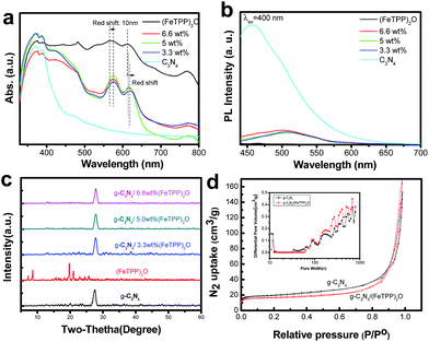
To clarify whether the heterostructure is successfully formed in the composite of g-C3N4/(FeTPP)2O, the optical properties of the above-mentioned materials were studied. Fig. 1a shows the UV-vis diffuse reflectance spectroscopy (DRS) of g-C3N4/(FeTPP)2O composites, pure g-C3N4 and (FeTPP)2O. The absorption peak of sole g-C3N4 is up to ∼450 nm, and has a small absorption tail which is probably due to n–π* transitions.44 The (FeTPP)2O has strong absorption in the visible region from 400 to 700 nm, mainly including two Q bands around 567 nm and 613 nm, which are similar to that of the (FeTPP)2O solution (Fig. S1†). The g-C3N4/(FeTPP)2O composites show the absorption features combining g-C3N4 and (FeTPP)2O, and exhibit wider absorption of solar light. As the content of g-C3N4 increased, the obvious red-shift of the Q band of (FeTPP)2O in composites can be found, which suggests π–π stacking interactions between g-C3N4 and (FeTPP)2O.45,46
Photoluminescence (PL) is an effective and commonly used method to investigate the electron transfer property of semiconductor materials.45,46Fig. 1b displays the PL spectra of g-C3N4, pure (FeTPP)2O and g-C3N4/(FeTPP)2O nanocomposites. Obviously, g-C3N4 has a strong and wide emission, in contrast, (FeTPP)2O has negligible PL signal response when the excited wavelength is 400 nm. The emission intensity of g-C3N4 remarkably decreased after it was combined with (FeTPP)2O. It means that the recombination of photo-excited holes and electrons of g-C3N4 is largely prohibited by (FeTPP)2O and that the charge transfer occurs in the composites. The big red shift of PL spectra of g-C3N4 in these composites also demonstrates the existence of interaction between g-C3N4 and (FeTPP)2O. On the basis of the above optical properties, it was guessed that their heterojunctions have been successfully prepared and the charge transfer may occur between them.
Wide-angle X-ray diffraction (XRD) patterns also confirm the presence of g-C3N4 in as-prepared samples. As shown in Fig. 1c, XRD patterns of g-C3N4 with different (FeTPP)2O contents exhibit a typical diffraction peak at 27.41°, which corresponds to the interlayer stacking of aromatic segments and indexed as (002). As compared to pure g-C3N4, no obvious (FeTPP)2O characteristic peaks can be found, indicating that g-C3N4/(FeTPP)2O retains the original crystal structure of g-C3N4. The same conclusion can also be made from BET experiments. The nitrogen adsorption–desorption isotherms of pure g-C3N4 and (FeTPP)2O-mediated g-C3N4 show type IV with hysteresis loops, indicating the presence of mesopores (Fig. 1d). The specific surface areas of pure g-C3N4 and g-C3N4/(FeTPP)2O (5.0 wt%) composites are 74 and 64 cm2 g−1, respectively. The inserted image in Fig. 1d indicates the similar mesopore structure between pure g-C3N4 and g-C3N4/(FeTPP)2O. These data suggest that the introduction of (FeTPP)2O into g-C3N4 lowers the specific surface areas of g-C3N4, however, it does not have any obvious effect on the mesopore structure of g-C3N4, which is closely related to its photocatalytic activity.
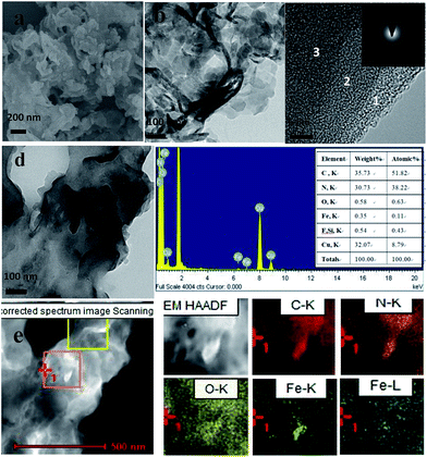
In order to further investigate the components and structure of g-C3N4/(FeTPP)2O composites, scanning electron microscopy (SEM, JSM-6700F, JEOL, Inc.) and transmission electron microscopy (TEM, F20, FEI) were used. The corresponding images are shown in Fig. 2. As compared to g-C3N4 shown in Fig. S4,† which has smooth folded nanosheets besides some fragments, (FeTPP)2O in Fig. S5† is composed of a lot of aggregations of amorphous nanoparticles (NPs) or naonoplates. After (FeTPP)2O was introduced into the as-obtained g-C3N4, many small NPs can be found on g-C3N4 sheets and quite a lot of aggregations are attached on g-C3N4, as shown in Fig. 2a and b. The TEM image in Fig. 2b exhibits that the g-C3N4/(FeTPP)2O heterostructure still retains the morphology of g-C3N4. Fig. 2c clearly displays a typical layer-by-layer structure of g-C3N4 according to the difference of image contrast, and the inserted selected area electron diffraction (SAED) image indicates a low crystallinity of g-C3N4 in the composite. A clue to the existence of (FeTPP)2O can be found in the TEM image shown in Fig. 2d. In order to further prove the existence of (FeTPP)2O, the corresponding energy dispersive X-ray spectroscopy (EDS) was also performed on the sample. The result in Fig. 2d shows that Fe–K peaks exist in the spectrum and their percent content is calculated to be ∼0.11 at%, which is close to the content in theory (5 wt%). At the same region of the sample, TEM-assisted elemental mappings were carried out and the results are shown in Fig. 2e. The Fe–K mapping in Fig. 2e further indicates that the NPs of (FeTPP)2O exist and they should be equably distributed on the surface of g-C3N4 nanosheets. The above results further demonstrate the successful formation of the g-C3N4/(FeTPP)2O heterostructure and the intimate contact between g-C3N4 and (FeTPP)2O. Interestingly, although at least two obvious NPs can be found in the orange square in Fig. 2e, as compared to Fig. 2d, only one (FeTPP)2O nanoparticle can be found in the Fe–K mapping. It means that most of the NPs or nanoplates should be fragments of g-C3N4 as a result of the reaction between g-C3N4 and the precursor of (FeTPP)2O.
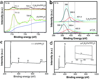
To further understand the interaction of the two components, X-ray photoelectron spectroscopy (XPS) was performed on these samples. The binding energies of Fe 2p3/2 of (FeTPP)2O and g-C3N4/(FeTPP)2O are 711.5 eV and 711.1 eV (Fig. 3a), respectively, the decrease of 0.4 eV in the binding energy of Fe 2p3/2 might be caused by the interaction between (FeTPP)2O and g-C3N4, which indicates the formation of an Fe–N bond because the N element has lower electron affinity than O.47 The binding energy of Fe 2p1/2 also has the same tendency. To prove the interaction, N 1s XPS spectra of pure g-C3N4 and g-C3N4/(FeTPP)2O were also measured and compared, and the results are exhibited in Fig. 3b. Three peaks at ca. 398.3, 399.4 and 400.9 eV are observed for single g-C3N4. The main N 1s peak at 398.3 eV corresponds to the sp2 hybridized aromatic N bonded to carbon atoms (C–N–C). The peak at 399.4 eV is assigned to the tertiary N bonded to carbon atoms in the form of N–(C)3 or H–N–(C)2. And the weak peak with a high binding energy at 400.9 eV is attributed to the quaternary N bonded to three carbon atoms in the aromatic cycles.15,42,43 After forming the heterostructure with (FeTPP)2O, all the N 1s peaks of g-C3N4 shift to a higher binding energy, corresponding to the decrease of the Fe 2p binding energy. Apparently, a strong interaction between (FeTPP)2O and g-C3N4 is built through the formation of the Fe–N bond.48 As compared to the relative atomic concentration of Fe (1.29 at%) in the pure (FeTPP)2O composite shown in Fig. 3c, that of the g-C3N4/(FeTPP)2O composite is 0.21 atom% estimated from the XPS data. The result is higher than that from the EDS and our theoretical data because the XPS data are usually collected from the sample surface. The above XPS data indicate that in the as-obtained samples, (FeTPP)2O is on the surface of g-C3N4 and they form the heterostructure through π–π and the Fe–amine interactions.
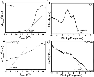
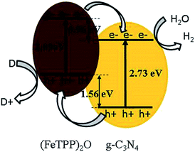
Between g-C3N4 and (FeTPP)2O, the charge transfer has been revealed in the PL spectra, the SEM, TEM and XPS data have also demonstrated the formation of the heterostructure. However, only the relative band positions of the two components can tell us the direction of charge transfer and the type of the heterojunction. Based on the UV-vis diffuse reflectance data, the band-gap energy was calculated according to Fig. 4a and c. The band gap of g-C3N4 and (FeTPP)2O are 2.73 eV and 2.09 eV, respectively. The valence band XPS (VB XPS) spectra of g-C3N4 and (FeTPP)2O were measured, as shown in Fig. 4b and d, the valence band (VB) of (FeTPP)2O is more negative about 1.56 eV than that of g-C3N4. Together with their band gaps we can deduce that the conduction band (CB) of (FeTPP)2O is more negative about 0.96 eV than that of g-C3N4. As illustrated in Scheme 1, the band alignment of g-C3N4 and (FeTPP)2O forms the typical type II heterojunction.49,50 The large CB and VB offsets between g-C3N4 and (FeTPP)2O make the photo-generated electrons transfer from (FeTPP)2O to g-C3N4, while the photo-generated holes migrate from g-C3N4 to (FeTPP)2O in a thermodynamically favorable manner, which leads to an efficient charge separation and significant enhancement in photocatalytic activity.36,50
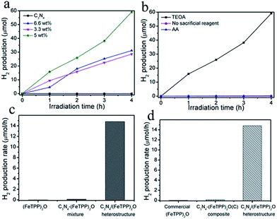
Solar-light-induced H2 production was investigated to examine the photocatalytic activity of the as-prepared samples. Fig. 5a shows the varied amount of H2 evolution under solar light for various photocatalysts. Almost no H2 can be detected when only g-C3N4 was used as the photocatalyst. It may be due to the detrimental electron-hole recombination and the Frenkel exciton effect. In contrast, the g-C3N4/(FeTPP)2O composite exhibited dramatic photocatalytic H2 production. Here, the loading amount of (FeTPP)2O plays an important role in tailoring the photocatalytic activity of the heterostructures. With the content of (FeTPP)2O increased, the amount of H2 first increases and then decreases. The experiments in Fig. 5 show that the optimal amount of (FeTPP)2O is about 5.0 wt%, and the best sample produces 59.2 μmol H2 under solar light irradiation for 4 h. As we know, for the photocatalytic activity of the heterostructure nanocomposites, two factors have a serious effect on the hydrogen evolution. One is the capability of light absorption, the other is the amount of activity sites on the surface of the composite. In our system, the (FeTPP)2O plays a dual role of dye-sensitization and charge transfer for g-C3N4. In some ranges, more doping of the guest means the formation of more heterojunctions (activity sites) and stronger absorption in visible-light. With the further increase of doping beyond some amount, however, surface activity sites and/or absorption actually decrease. Therefore, there is always an optimal doping ratio. As far as the g-C3N4/(FeTPP)2O composite is concerned, the decrease of its specific surface areas with the increase of the amount of (FeTPP)2O (see Fig. 1d) means that the optimal ratio of (FeTPP)2O in the heterostructure is determined by its visible-light absorption. UV-vis DRS in Fig. 1a clearly shows that the ratio should be ∼5.0 wt%, which is consistent with our experimental results in Fig. 5.
Furthermore, it was found that sacrificial electron donors are also essential for the consumption of photo-generated holes and the regeneration of (FeTPP)2O. As shown in Fig. 5b, without any electron donors, no H2 is produced. The presence of ascorbic acid (AA) also has little effect on promoting the activity of g-C3N4/(FeTPP)2O heterostructures, while the addition of triethanolamine (TEOA) significantly enhances the photocatalytic H2 production. The reason must be ascribed to the highest redox potential and the created basic circumstance of TEOA.51 Apparently, sole (FeTPP)2O shows no activity toward water splitting, as shown in Fig. 5c. It must be noted that the physical mixture of g-C3N4 and (FeTPP)2O failed to produce the heterostructure, thus the mixture also shows negligible photocatalytic activity.52 In addition, commercial (FeTPP)2O was also thought to combine with g-C3N4 in a physical manner. Through impregnation of g-C3N4 with a dichloromethane solution of commercial (FeTPP)2O overnight, the composite of g-C3N4/(FeTPP)2O was prepared. However, Fig. 5d shows that the corresponding composite also exhibits negligible H2 production. Therefore, the formation the Fe–N bond between g-C3N4 and (FeTPP)2O should play a key role in the solar H2 production from water splitting.
Hydrogen evolution measurement under UV-vis light irradiation with a 300 W Xenon lamp was also investigated. The durability of g-C3N4/(FeTPP)2O (5.0 wt%) acting as the photocatalyst for H2 evolution was evaluated by three consecutive operations. As shown in Fig. S6,† UV-vis-light can stimulate the photocatalyst to produce H2 at a rate of ∼40 μmol h−1 and the amount of H2 increases with irradiation time. Followed by the first run, some deactivation was observed in the second run. Interestingly, after the second cycle and lighting off for several hours, some photocatalytic activity was recovered in the third cycle. The deactivation should have occurred due to the non-renewable consumption of the (FeTPP)2O in the photocatalytic process,47 while the recovery is ascribed to the partial regeneration of (FeTPP)2O with TEOA in the dark. In addition, under visible light (λ > 420 nm) generated by using an Xenon lamp with a UV-cutoff filter, H2 evolution is 11 μmol h−1 (see Fig. S7†). At 420 nm, a quantum efficiency (QE) of 0.0415% was obtained.53
Conclusions
In conclusion, through a simple liquid chemical reaction between g-C3N4 and the precursor of (FeTPP)2O, we presented a novel route to construct a pure organic heterostructure of g-C3N4/(FeTPP)2O as a photocatalyst for solar H2 production from water splitting. The (FeTPP)2O was found attached to g-C3N4 through the π–π interaction and Fe–N bond. The composite exhibited a significant enhancement in photocatalytic activity due to efficient light utilization and the charge separation which arises from the band offsets. Besides the loading amount of (FeTPP)2O and the type of sacrificial electron donors, it was found that the formation of Fe–amine interactions between g-C3N4 and (FeTPP)2O should play a key role in the solar H2 production from water splitting. A further study on the effect of the Fe–N bond between g-C3N4 and (FeTPP)2O on photocatalytic activity is in progress. In a word, an efficient chemical path to significantly promote light harvesting and the charge transfer of g-C3N4 was achieved through the construction of a heterostructure between organic small molecules and g-C3N4. This work is expected to promote the research and application of g-C3N4 for solar H2 production in the absence of cocatalysts.Experimental
Materials
Silver perchlorate, tetraphenyl iron(III) porphyrin chloride (FeTPPCl), anhydrous dichloromethane and acetonitrile (water < 30 ppm) were purchased from J&K Chemicals Co. Ultrapure water with a resistivity of 18.2 MΩ cm was produced using a Water Purifier apparatus (WP-UP-IV-20). Urea (10 g, AR) was obtained from Sinopharm Chemical Reagent Co., China.Synthesis of g-C3N4
Graphitic carbon nitride (g-C3N4) was synthesized by thermal treatment of urea (10 g, AR) in a lidded high quality alumina crucible covered with aluminium foil under ambient pressure in air. The crucible was placed in a high temperature box furnace (KSL-1100X-S) and heated to 600 °C for 3.0 h, and then raised to 650 °C for 0.5 h to complete the reaction. The synthesized yellow mass was crushed to powder (330 mg) for further experiments.Synthesis of tetraphenyl iron(III) porphyrin perchlorate
A precursor of tetraphenyl iron(III) porphyrin perchlorate was produced via reaction (1):| FeTPPCl + AgClO4 = AgCl + FeTPP+·ClO4+ | (1) |
In a typical synthesis, a solution of dry silver perchlorate in a minimum amount of anhydrous acetonitrile (0.6 mL, 0.30 mM) was added into a 16 mL solution of 0.27 mM FeTPPCl in anhydrous dichloromethane with stirring. After stirring for about 3 h, the mixture was separated by centrifuging at 10![[thin space (1/6-em)]](https://www.rsc.org/images/entities/char_2009.gif) 000 rpm for 10 min. Relying on the difference in solubility between silver chloride and FeTPPClO4 in acetonitrile, a brown FeTPPClO4 solution is separated from the admixture. The solution was poured into 50 mL n-hexane and placed in a fridge at −22 °C for 24 h. Then the precipitation was obtained through centrifuging at 10
000 rpm for 10 min. Relying on the difference in solubility between silver chloride and FeTPPClO4 in acetonitrile, a brown FeTPPClO4 solution is separated from the admixture. The solution was poured into 50 mL n-hexane and placed in a fridge at −22 °C for 24 h. Then the precipitation was obtained through centrifuging at 10![[thin space (1/6-em)]](https://www.rsc.org/images/entities/char_2009.gif) 000 rpm for 2 min and further washed with n-hexane two times. The as-obtained product was dried for further use.
000 rpm for 2 min and further washed with n-hexane two times. The as-obtained product was dried for further use.
Synthesis of C3N4/(FeTPP)2O (5 wt%) nanocomposites
Typically, g-C3N4 (80 mg) powder was added into 100 mL of ultrapure water and sonicated at 800 W for 2 h. 4 mg of FeTPPClO4 was dissolved in 8 mL of anhydrous acetonitrile. Under stirring, the solution of FeTPPClO4 was added dropwise into the C3N4 dispersion, and kept stirring for 1.5 h. The composite was obtained through vacuum filtration and washed twice with ultrapure water.Characterization
FESEM images were recorded with a Hitachi SU8010 instrument. Samples casted on a copper grid were observed via a transmission electron microscope (TEM, F20). The UV-vis absorption spectra were obtained on a Perkin Elmer Lambda 950 UV-vis spectrophotometer equipped with an integrating sphere. BaSO4 was used as a reflectance standard in the diffuse reflectance experiments. FT-IR spectra were recorded on a VERTEX70 FTIR spectrometer when samples were embedded in KBr pellets. Photoluminescence (PL) spectra were recorded with a Hitachi F-4600 fluorescence spectrophotometer. X-Ray photoelectron spectroscopy (XPS) was performed with a Thermo Scientific ESCALAB 250Xi system. X-ray powder diffraction patterns were recorded with a Rigaku MiniFlex II diffractometer with a Cu sealed tube. N2 physisorption isotherms of g-C3N4 and g-C3N4/(FeTPP)2O were measured using a Micromeritics ASAP 2020 surface area and porosimetry analyser.Photocatalytic activity measurements
Photocatalytic water splitting reactions were carried out in a Pyrex top-irradiation reaction vessel connected to a closed glass gas circulation system (Labsolar III AG, Beijing Perfectlight Technology Co. Ltd). 80 mg of C3N4, C3N4/(FeTPP)2O composites or 4 mg of (FeTPP)2O was dispersed in 90 mL of ultrapure water by sonication, and then 10 mL of TEOA was added into it. The reaction system was evacuated for 30 min to remove the dissolved gases in water prior to irradiation under a 300 W Xe lamp (PLS-SXE 300). A continuous magnetic stirrer was applied at the bottom of the reactor in order to keep the photocatalytic particles suspended in water during the whole experiment. The wavelength of the incident light was controlled by using a solar simulator filter for solar light irradiation. The temperature of the reactant solution was maintained at room temperature by a flow of cooling water during the reaction. The evolved gases were analyzed by gas chromatography (GC 7900, Shanghai Techcomp Instrument Ltd.). H2 evolution under visible light (λ > 420 nm) was measured by using a 300 W Xe lamp combined with a UV-cutoff filter. The quantum efficiency (QE) was obtained by applying a Xe lamp (300 W) with a 420 nm bandpass filter. The number of incident photons was measured using a radiant power energy meter (MC UV-A). The QE was calculated using the following equation:Acknowledgements
The authors gratefully acknowledge the financial support from the National Natural Science Foundation of China (No. 21252001, 21473204), the Special Project of National Major Scientific Equipment Development of China (No. 2012YQ120060), the Natural Science Foundation of Fujian Province (2015J01070), and the Science and Technology Planning Project of Fujian Province, Grant No. 2014H2008.Notes and references
- A. J. Bard and M. A. Fox, Acc. Chem. Res., 1995, 28, 141 CrossRef CAS.
- S. S. Penner, Energy, 2006, 31, 33 CrossRef CAS; A. J. Esswein and D. G. Nocera, Chem. Rev., 2007, 107, 4022 CrossRef PubMed.
- K. Maeda and K. Domen, J. Phys. Chem. Lett., 2010, 1, 2655 CrossRef CAS.
- R. F. Service, Science, 2007, 315, 789 CrossRef CAS PubMed.
- H. G. Kim, D. W. Hwang and J. S. Lee, J. Am. Chem. Soc., 2004, 126, 8912 CrossRef CAS PubMed.
- K. Maeda and K. Domen, J. Phys. Chem. C, 2007, 111, 7851 CAS.
- X. B. Chen, S. H. Shen, L. J. Guo and S. S. Mao, Chem. Rev., 2010, 110, 6503 CrossRef CAS PubMed.
- F. E. Osterloh, Chem. Mater., 2008, 20, 35 CrossRef CAS.
- K. Maeda and K. Domen, Chem. Mater., 2010, 22, 612 CrossRef CAS.
- F. E. Osterloh, Chem. Soc. Rev., 2013, 42, 2294 RSC.
- X. C. Wang, K. Maeda, A. Thomas, K. Takanabe, G. Xin, J. M. Carlsson, K. Domen and M. Antonietti, Nat. Mater., 2009, 8, 76 CrossRef CAS PubMed.
- S. W. Cao, J. X. Low, J. G. Yu and M. Jaroniec, Adv. Mater., 2015, 27, 2150 CrossRef CAS PubMed.
- Y. Zheng, J. Liu, J. Liang, M. Jaroniec and S. Z. Qiao, Energy Environ. Sci., 2012, 5, 6717 CAS.
- A. Thomas, A. Fischer, F. Goettmann, M. Antonietti, J. O. Müller, R. Schlögl and J. M. Carlsson, J. Mater. Chem., 2008, 18, 4893 RSC.
- F. Dong, L. W. Wu, Y. J. Sun, M. Fu, Z. B. Wu and S. C. Lee, J. Mater. Chem., 2011, 21, 15171 RSC.
- Y. W. Zhang, J. H. Liu, G. Wu and W. Chen, Nanoscale, 2012, 4, 5300 RSC.
- H. J. Yan, Y. Chen and S. M. Xu, Int. J. Hydrogen Energy, 2012, 37, 125 CrossRef CAS.
- Y. J. Zhong, Z. Q. Wang, J. Y. Feng, S. C. Yan, H. T. Zhang, Z. S. Li and Z. G. Zou, Appl. Surf. Sci., 2014, 295, 253 CrossRef CAS.
- Y. Wang, X. C. Wang and M. Antonietti, Angew. Chem., Int. Ed., 2012, 51, 68 CrossRef CAS PubMed.
- Z. W. Zhao, Y. J. Sun and F. Dong, Nanoscale, 2015, 7, 15 RSC.
- S. Cao and J. Yu, J. Phys. Chem. Lett., 2014, 5, 2101 CrossRef CAS PubMed.
- X. C. Wang, K. Maeda, X. F. Chen, K. Takanabe, K. Domen, Y. D. Hou, X. Z. Fu and M. Antonietti, J. Am. Chem. Soc., 2009, 131, 1680 CrossRef CAS PubMed.
- J. S. Zhang, M. W. Zhang, C. Yang and X. C. Wang, Adv. Mater., 2014, 26, 4121 CrossRef CAS PubMed.
- J. H. Sun, J. S. Zhang, M. W. Zhang, M. Antonietti, X. Z. Fu and X. C. Wang, Nat. Commun., 2012, 3, 1139 CrossRef.
- Z. Z. Lin and X. C. Wang, Angew. Chem., Int. Ed., 2013, 52, 1735 CrossRef CAS PubMed.
- G. G. Zhang, M. W. Zhang, X. X. Ye, X. Q. Qiu, S. Lin and X. C. Wang, Adv. Mater., 2014, 26, 805 CrossRef CAS PubMed.
- L. Ge, F. Zuo, J. K. Liu, Q. Ma, C. Wang, D. Z. Sun, L. Bartels and P. Y. Feng, J. Phys. Chem. C, 2012, 116, 13708 CAS.
- Y. F. Zhang, F. Mao, H. J. Yan, K. W. Liu, H. M. Cao, J. G. Wu and D. Q. Xiao, J. Mater. Chem. A, 2015, 3, 109 CAS.
- X. H. Zhang, T. Y. Peng, L. J. Yu, R. J. Li, Q. Q. Li and Z. Li, ACS Catal., 2015, 5, 504 CrossRef CAS.
- H. L. Wang, L. S. Zhang, Z. G. Chen, J. Q. Hu, S. J. Li, Z. H. Wang, J. S. Liu and X. C. Wang, Chem. Soc. Rev., 2014, 43, 5234 RSC.
- S. J. A. Moniz, S. A. Shevlin, D. J. Martin, Z. X. Guo and J. W. Tang, Energy Environ. Sci., 2015, 8, 731 CAS.
- M. Muntwiler, Q. Yang and X. Zhu, J. Electron Spectrosc. Relat. Phenom., 2009, 174, 116 CrossRef CAS.
- C. Piliego and M. A. Loi, J. Mater. Chem., 2012, 22, 4141 RSC.
- H. J. Yan and Y. Huang, Chem. Commun., 2011, 47, 4168 RSC.
- X. J. Bai, C. P. Sun, S. L. Wu and Y. F. Zhu, J. Mater. Chem. A, 2015, 3, 2741 CAS.
- J. S. Zhang, M. W. Zhang, R. Q. Sun and X. C. Wang, Angew. Chem., 2012, 124, 10292 CrossRef.
- T. Higashino and H. Imahori, Dalton Trans., 2015, 44, 448 RSC.
- Q. Liu, Y. Z. Gong, C. J. Gong, Q. H. Li and C. C. Guo, J. Porphyrins Phthalocyanines, 2009, 13, 854 CrossRef CAS.
- K. Takanabe, K. Kamata, X. C. Wang, M. Antonietti, J. Kubota and K. Domen, Phys. Chem. Chem. Phys., 2010, 12, 13020 RSC.
- J. Y. Xu, Y. X. Li, S. Q. Peng, G. X. Lu and S. B. Li, Phys. Chem. Chem. Phys., 2013, 15, 7657 RSC.
- L. J. Yu, X. H. Zhang, C. S. Zhuang, L. Lin, R. J. Li and T. Y. Peng, Phys. Chem. Chem. Phys., 2014, 16, 4106 RSC.
- J. H. Liu, T. K. Zhang, Z. C. Wang, G. Dawson and W. Chen, J. Mater. Chem., 2011, 21, 14398 RSC.
- D. J. Martin, K. P. Qiu, S. A. Shevlin, A. D. Handoko, X. W. Chen, Z. X. Guo and J. W. Tang, Angew. Chem., Int. Ed., 2014, 53, 9240 CrossRef CAS PubMed.
- A. B. Jorge, D. J. Martin, M. T. S. Dhanoa, A. S. Rahman, N. Makwana, J. W. Tang, A. Sella, F. Corà, S. Firth, J. A. Darr and P. F. McMillan, J. Phys. Chem. C, 2013, 117, 7178 CAS.
- D. M. Chen, K. W. Wang, W. Z. Hong, R. L. Zong, W. Q. Yao and Y. F. Zhu, Appl. Catal., B, 2015, 166, 366 CrossRef.
- M. S. Zhu, Z. Li, B. Xiao, Y. T. Lu, Y. K. Du, P. Yang and X. M. Wang, ACS Appl. Mater. Interfaces, 2013, 5, 1732 CAS.
- D. D. Wang, J. Huang, X. Li, P. Yang, Y. K. Du, C. M. Goh and C. Lu, J. Mater. Chem. A, 2015, 3, 4195 CAS.
- D. H. Wang, L. Jia, X. L. Wu, L. Q. Lu and A. W. Xu, Nanoscale, 2012, 4, 576 RSC.
- S. S. Chen, Y. Qi, T. Hisatomi, Q. Ding, T. Asai, Z. Li, S. S. K. Ma, F. X. Zhang, K. Domen and C. Li, Angew. Chem., Int. Ed., 2015, 29, 8498–8501 CrossRef PubMed.
- M. R. Gholipour, C. T. Dinh, F. Bélandb and T. O. Do, Nanoscale, 2015, 7, 8187 RSC.
- X. H. Zhang, L. J. Yu, C. S. Zhuang, T. Y. Peng, R. J. Li and X. G. Li, ACS Catal., 2014, 4, 162 CrossRef CAS.
- S. W. Cao, Y. P. Yuan, J. Barber, S. C. J. Loo and C. Xue, Appl. Surf. Sci., 2014, 319, 344 CrossRef CAS.
- The measurement of quantum efficiency at 420 nm: k = 1.01 × 10⁻⁹ mol s−1, k is numbers of H2 evolution per second. qp = p × λ/(h × c), in which qp is the number of photons per second, P is illumination intensity (1.387 J s−1), λ is incident wavelength of 420 nm, c is the speed of light (3 × 10⁸ m s−1), h is Planck’s constant (6.626 × 10⁻³⁴ J s−1). Thus, QE = 2k/qp = (2 × 1.01 × 10−9 mol s−1)/(4.87 × 10−6 mol s−1) = 0.0415%.
Footnote |
| † Electronic supplementary information (ESI) available. See DOI: 10.1039/c5ta07278f |
| This journal is © The Royal Society of Chemistry 2016 |

