Self-activated continuous pulverization film: an insight into the mechanism of the extraordinary long-life cyclability of hexagonal H4.5Mo5.25O18·(H2O)1.36 microrods†
Zihua
Li
ab,
Hai
Wang
*ab,
Zhuangzhi
Sun
ab,
Jian
Su
ab,
Zuyun
Wang
c and
Linjiang
Wang
ab
aCollege of Materials Science and Engineering, Guilin University of Technology, Guilin 541004, China. E-mail: hbwanghai@gmail.com; Fax: +86-773-5896-671; Tel: +86-773-5896-672
bKey Laboratory of New Processing Technology for Nonferrous Metals and Materials, Ministry of Education, Guilin University of Technology, Guilin 541004, China
cCollege of Civil Engineering and Architecture, Guilin University of Technology, Guilin 541004, China
First published on 16th November 2015
Abstract
For large amounts of transition metal oxides, sulfides and carbon groups (IVA), the pulverization of electrode materials in lithium-ion batteries (LIBs) is always a serious and common problem due to volume expansion and stress accumulation resulting from phase transformation or alloying during the charge–discharge process, which leads to capacity fading and thus limits the cycling performance of LIBs. To solve these problems, conventionally, the rational design of electrode materials is needed. Here in this work, we report the synthesis of a novel anode material, hexagonal H4.5Mo5.25O18·(H2O)1.36 microrods (HMs) via a simple hydrothermal method. During the lithium-ion insertion/desertion process of the HMs, it was found that the HMs are first drastically transformed into Li2MoO4 nanotubes and then Li2MoO4 nanowire clusters embedded in amorphous sphere cages with a Li2O matrix, Mo metal and SEI thin film. Surprisingly, we discovered that the HMs exhibited extraordinary long-life cyclability with an unusual phenomenon: the specific capacity first decreased and then increased. The outstanding electrochemical performance could be explained by the formation of intermediate phase Li2MoO4 nanowires and amorphous sphere cages, which can maintain the lithium-ion paths and electronic transport, and prohibit the mechanical and chemical degradation of the electrode materials. The results show that the pulverization of the HM anode materials induced by lithium-ion insertion–extraction played a trigger role in the formation of a continuous pulverization film. Accordingly, a “damage-reconstruction” model based on ex situ XRD and FESEM analyses combined with ex situ XPS, FTIR and TEM characterizations of the charge–discharge process was proposed to explain such an unusual and intriguing finding. Compared with the conventional method for protecting electrode materials from pulverization, the robust continuous gel-like pulverization film containing a unique combination of intermediate phase and amorphous sphere cages provides a new insight into the mechanism for the extraordinary long-term cyclability of electrode materials.
Introduction
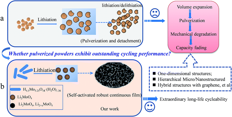
It is well known that the pulverization of electrode materials in lithium-ion batteries (LIBs) is a serious and common problem for the future commercial application of LIBs, especially for most transition metal oxides, sulphides and carbon groups (IVA), e.g., MoO3,1–5 SnO2,6–8 NiCo2O4,9–11 Sn,12–15 Ge,16–18 Si19–21 and so on. Generally speaking, the reason for the pulverization involves two main factors, which are volume expansion and phase transformation during the charge–discharge process. Especially in transition metal oxide electrode materials, the formation of amorphous metal nanoclusters, Li2O and SEI layers is unavoidable during the lithium-ion insertion/desertion process.5,7,10,17 Usually, these pulverized powders will detach and drop off, and are not connected to each other after long cycling (Scheme 1a). To prevent electrode materials from pulverizing, based on the analysis of a large amount of previous literature and the basic principle of the pulverization of electrode materials, it can be concluded that exploring novel electrode materials is needed. For example, the structural design of novel electrode materials has included one-dimensional and mesoporous structures of active materials, hybrid composites, such as carbon materials and graphene, other novel structures, and so on.1,5,7–9,20,22–24An accepted fact is that almost all of the electrochemical reactions for electrode materials mentioned above involve a great volume change. In this regard, therefore, the ability to connect different particles and make them stable will be crucial for maximizing the performance of a material with a long cycle life. In our study, Scheme 1b proposes a new concept for interconnecting pulverization particles. In this proof of concept, the pulverized powders were held together closely. Moreover, the pulverized powders can be self-activated by lithium-ion insertion/desertion, and can finally form a continuous robust film. This pulverization film has at least three advantages for long-life LIB application: (1) the film is robust without any detachment occurring with long-life cycles; (2) the lithium-ion insertion and desertion are confined to within the continuous film without large lithium-ion loss; (3) the enhanced large surface area of the electrode materials driven by the pulverization method will further provide more active sites for the lithium-ion insertion/desertion.
MoO3, as a promising electrode material, has been extensively investigated by many groups due to its unique layer structure and high theoretical capacity in LIB application.1–4 However, its relatively low specific capacity still holds back its practical application. Very recently, we demonstrated that HxMoO3, belonging to MxMoO3·nH2O, is a superior electrode material compared with MoO3, due to its metallic and layer structure features.25 Over the past two decades, hexagonal molybdates with the general formula, My·zH2O, Mo6−xO18−xH4x−y have been reported.26 From the perspective of crystal structure, the most distinguishing structural feature of the hexagonal molybdates is a wide one-dimensional tunnel (3.2–3.5 Å in diameter), which should allow lithium-ions free intercalation.26 However, their LIB performance and corresponding electrochemical mechanism are still uncertain. Actually, large amounts of space in the above mentioned materials for lithium ion insertion and desertion is ideal for the design of electrode materials. The unique and wide one-dimensional tunnel motivated us to explore the synthesis and energy storage performance of new molybdenum-related materials. Some similar molybdate materials have already been reported, such as (NH4)Mo5.3O17.3H1.7·0.4H2O, Na1.0Mo5.35O17.35H1.6·1.7H2O and so on, and their corresponding electrochemical properties have been preliminarily investigated.26 Although some similar materials, such as (H3O)yMoO3·zH2O, were obtained typically in two steps, which include the formation of a sodium form and multiple acid treatment, to the best of our knowledge, H4.5Mo5.25O18·(H2O)1.36 has rarely been reported to date.26 Therefore, the facile synthesis of hexagonal H4.5Mo5.25O18·(H2O)1.36 is highly desirable.
Here, we have synthesized H4.5Mo5.25O18·(H2O)1.36 microrods (HMs) for the first time via a simple one-step hydrothermal method with the assistance of PVP and formic acid. In our work, we take HMs as a typical case, and address the concept of connecting pulverized particles for the first time. As a result, when tested as anode materials in LIBs, we found that this novel anode material was an ideal electrode material with a high capacity (initial capacity was 2072 mA h g−1), fantastic long life span (without fade, even up to 1000 cycles) and superior rate performance. To reveal the relationship between the microstructure and electrochemical performance, especially cycle performance, we use ex situ XRD and FESEM combined with other characterization, such as XPS, TEM, FTIR and so on, to investigate the electrochemical mechanism. Astonishingly, we discovered that the extraordinary long-term cyclability of HMs may be attributed to the formation of robust continuous pulverization gel-like films. The damage to the HMs and the reconstruction of intermediate Li2MoO4 nanowires within spheres of amorphous Mo metal, Li2O matrix and SEI thin film may be critical factors in this unusual phenomenon.
Experimental section
Material synthesis
All reagents were analytical grade and used without any further purification. In a typical synthesis, 30 mL of formic acid was slowly added to an aqueous solution of PVP (1 g of PVP dissolved in 30 mL of deionized water) in a flask under vigorous stirring. After being continuously stirred for 30 min in the flask, 1 g of ammonium molybdate (NH4)6Mo7O24·4H2O powder was added to the above mixture solution and continuously stirred for another 30 minutes. Finally, the resultant suspension was transferred to a Teflon-lined stainless steel autoclave (100 mL volume) for hydrothermal treatment at 180 °C for 6 h. The autoclave was cooled to room temperature; the blue precipitates were collected by means of centrifugation, washed several times with deionized water and ethanol, and then dried under vacuum at 70 °C for 24 h. To explore the role of formic acid, PVP and deionized water in the formation of the HMs, control experiments involving no water, no PVP and no formic acid were performed, respectively. Specifically, HMs with different volume ratios of formic acid and H2O are denoted as HM-10, HM-20, HM-30. 10, 20, and 30 are the different formic acid volumes, respectively. The total combined volume of formic acid and H2O remained as 60 mL.Material characterizations
The crystal structures were investigated using X-ray diffraction (XRD) analyses with a PANanalytic X'Pert spectrometer using Cu Kα radiation, λ = 0.15405 nm. The high-resolution transmission electron microscopy (HRTEM) images were obtained with a JEOL JEM-2010F microscope operating at 200 kV. X-ray photoelectron spectroscopy (XPS) spectra were performed to analyse the surface of the samples in different charge–discharge stages on an ESCALAB210 spectrometer using Al anode Kα (hν = 1486.61 eV) radiation as the excitation source of monochromatic X-rays under ultrahigh vacuum (UHV) with a base pressure of 10−10 mbar. Fourier transform infrared (FTIR) absorption spectra were recorded on a Nicolet 6700 spectrometer (Thermo Fisher Scientific Inc., USA) from 4000 to 500 cm−1 using KBr pellets as the dispersant. The specific surface area was measured by the Brunauer–Emmett–Teller (BET) approach using adsorption data over a relative pressure range, while the pore size and its distribution were calculated by the Barrett–Joyner–Halenda (BJH) method based on the obtained desorption curves.Electrochemical measurements
The electrochemical measurements were carried out using CR2025-type coin cells with pure lithium metal for both the counter electrode and the reference electrode at room temperature. The working electrode consisted of active material, a conductive agent (carbon black, Super-P-Li), and a polymer binder (poly(vinylidene difluoride), PVDF, Aldrich) in a 70![[thin space (1/6-em)]](https://www.rsc.org/images/entities/char_2009.gif) :
:![[thin space (1/6-em)]](https://www.rsc.org/images/entities/char_2009.gif) 20
20![[thin space (1/6-em)]](https://www.rsc.org/images/entities/char_2009.gif) :
:![[thin space (1/6-em)]](https://www.rsc.org/images/entities/char_2009.gif) 10 weight ratio. A Celgard 3400 membrane was used as a separator and 1.0 M LiPF6 in a mixture of ethylene carbonate–diethyl carbonate (1
10 weight ratio. A Celgard 3400 membrane was used as a separator and 1.0 M LiPF6 in a mixture of ethylene carbonate–diethyl carbonate (1![[thin space (1/6-em)]](https://www.rsc.org/images/entities/char_2009.gif) :
:![[thin space (1/6-em)]](https://www.rsc.org/images/entities/char_2009.gif) 1 volume, Novolyte Technologies, USA) was used as the electrolyte. The cell assembly was carried out in an Ar-filled glovebox with the concentration of moisture and oxygen below 1.0 ppm. The charge/discharge cycling and cyclic voltammetry (CV) (0.01–3 V, 0.2 mV s−1) measurements were performed at room temperature with an electrochemical workstation (CHI 860 D, Beijing) using a battery testing system (NEWARE) at different current rates with a voltage window of 0.01–3 V. Electrochemical impedance spectroscopy (EIS) measurements were performed at frequencies ranging from 10−2 to 105 Hz.
1 volume, Novolyte Technologies, USA) was used as the electrolyte. The cell assembly was carried out in an Ar-filled glovebox with the concentration of moisture and oxygen below 1.0 ppm. The charge/discharge cycling and cyclic voltammetry (CV) (0.01–3 V, 0.2 mV s−1) measurements were performed at room temperature with an electrochemical workstation (CHI 860 D, Beijing) using a battery testing system (NEWARE) at different current rates with a voltage window of 0.01–3 V. Electrochemical impedance spectroscopy (EIS) measurements were performed at frequencies ranging from 10−2 to 105 Hz.
Results and discussion
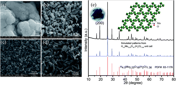
From the control experiments, it is observed that the PVP, formic acid and H2O obviously play a critical role in synthesizing the one-dimensional HMs, as shown in Fig. 1a–d. Interestingly, we also found that the volume ratio of the formic acid and H2O had an obvious effect on the aspect ratio of the HMs, as shown in Scheme S1.† Considering the importance of the unique structural features of one-dimensional architecture for LIB application, e.g. ZnFe2O4 microrods,27,28 we have taken hexagonal microrods for our investigation samples. For proof of concept, HM-30 was taken as the anode material case in our work.The corresponding XRD pattern for HM-30 is shown in Fig. 1e. This result agrees with the PDF: 83-1176. An obvious feature of the crystal structure is the one-dimensional tunnel (Fig. 1e inset). MoO6 is the basic building unit. In our previous reports, we found that HxMoO3 is a metal semiconductor with a blue color due to the co-existence of a mixture of Mo5+ and Mo6+ (Fig. 1e inset). PVP may play the role of a weak reduction agent during the reaction process, which has been reported in previous literature.29–33 The mixture of the valence of the transitional metals has been demonstrated to have a positive effect on the electrochemical performance, e.g. V, Ti.34–38 The objective of our work is to investigate the electrochemical properties of HM-30 which has both a one-dimensional microstructure and a tunnel structure. Therefore, we expected that the lithium-ions should insert into and desert the tunnel freely like a shuttle bus. Moreover, the crystal structure should be well retained. More lithium-ions would be easily intercalated into the HM-30, and provide a higher specific capacity. The expected good results are mainly based on the consideration of the following three factors: (1) the HM-30 structure has a wide one-dimensional pathway for lithium-ion diffusion; (2) the mixture of valence states Mo5+ and Mo6+ will provide good conductivity; (3) the one-dimensional microstructure will provide fast electron transfer. First, we tested the cycling performance of HM-30 at 1 A g−1. As shown in Fig. S1b,† we found that the initial specific capacity is high, up to 1637 mA h g−1. Surprisingly, we found that the specific capacity of the HM-30 sharply decreased to 152 mA h g−1 after 100 cycles, and then continuously increased. Furthermore, we evaluated the reproducibility of the electrochemical performance of the HM-30 by testing another batch of the sample, which was tested at different current densities, 0.5, 1 and 2 A g−1 under the same conditions as described above (Fig. S1†). The trend of specific capacity changes is similar: first quick fading, then continuous increasing. The unusual finding for HM-30 motivated us to explore the cycling performances of HM-10 and HM-20, as shown in Fig. S2 and S3,† respectively. The cycling performance results show that the phenomenon for these samples is similar to that for HM-30. The performance results of the three samples, HM-10, HM-20 and HM-30 are compared in Table S2.† We noted that there is also a similar phenomenon in previous literature. A possible explanation is a reactivation process for the active materials themselves during the charge–discharge process.39,40 Very recently, a high-rate lithiation-induced reactivation of mesoporous hollow spheres for long-lived lithium-ion batteries was reported by the Lian group. Lian et al. found that the capacity first faded and then increased by finely tuning the mesoporous structure of the metal oxide sphere and optimizing the stable solid–electrolyte interface (SEI) using high-rate lithiation-induced reactivation.41 In our case for HM-30, after such an unusual and intriguing finding, we decided to further focus on its microstructure and phase transformation as a function of different stages of cycles so as to obtain valuable information to better reveal its origin.
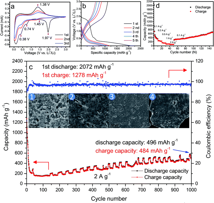
We first investigated the morphologies of the HM-30 after 1000 cycles. Surprisingly, we found that the one-dimensional microrods were damaged completely (Fig. 4c inset). Strikingly, the result is beyond our initial expectation. Hu et al. reported that the MoO3 hydrate is a metastable phase and can be stabilized by the presence of vanadium in view of the crystal structure perspective. Therefore, it is understandable that the HM-30 is completely damaged. This also motivated us to explore how the phase and the morphology of the HM-30 change at different stages of the charge–discharge process.
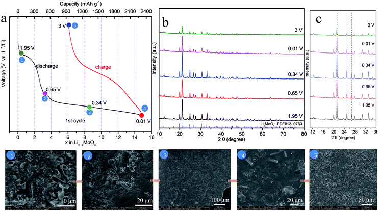
It is well-known that ex situ XRD and other advanced techniques are important tools to characterize the process of charge–discharge. We can monitor the phase transition process of HM-30 with the charge–discharge cycles. As shown in Fig. 2a, we chose five points to illustrate the whole change process of both the phase and morphology changes during the 1st charge–discharge process. The XRD results show that the main crystals are Li2MoO4 at 1.95 V, almost without any of the hexagonal H4.5Mo5.25O18·(H2O)1.36 crystal phase remaining, indicating that the phase change is complete (Fig. 2b). The transformation rate is also quite fast, ca. 18 min. This is the first report of how the Li2MoO4 nanotubes formed though the electrochemical reaction of a metastable phase H4.5Mo5.25O18·(H2O)1.36. Very recently, we also noticed that the Zhao group reported nanotubes of Li2MoO4.42 In the continuous lithium-ion insertion process, e.g. at 0.65, 0.34 and 0.01 V, we found that almost all of the (211) peak positions shifted slightly towards the left at 1.95, 0.65 and 3 V (Fig. 2c). Furthermore, we also found that some minor new phases were produced, e.g., LiMoO3, Li3MoO2.25, LiMo8O10 (denoted as LixMoyOz). These new minor phases may have an effect on the position of the (211) peak for Li2MoO4. Generally, the peak position should shift towards the left upon lithium-ion insertion due to the expansion of the crystalline lattice.
Furthermore, we also carried out corresponding ex situ FESEM images of HM-30, as shown in the inset of Fig. 2. The results show that the HM-30 first transformed into nanotubes after lithium-ion insertion. Moreover, the nanotubes finally disappeared after discharge at 0.34 V. Very interestingly, the powder began to transform into a robust continuous film. The surface feature of the thin film looks like a slurry and gel-like material, indicating that the pulverization particles were held together closely, which is obviously different from the previously reported literature. Actually, from the view of crystal structure, the HM-30 was changed into Li2MoO4 nanotubes, and some large volume changes had occurred. It has been addressed that the crystal structure change led to a great pulverization of HM-30, as shown in more detail in Table S1.†
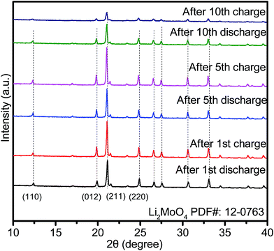
To reveal the phase composition changes, we compared the phase composition results for HM-30 after 1, 5 and 10 cycles. The results show that the main crystalline phase is still Li2MoO4, except for some minor phases, such as Li4MoO5, Li4Mo5O17, et al. (denoted as LixMoyOz) (Fig. 3). Surprisingly, there are some obvious peak shifts toward lower angles, indicating continuous lithium-ion intercalation, which is different from the 1st discharge. Additionally, the relative intensity of the peaks for Li2MoO4 became weak from the 5th discharge, indicating that the nanocrystalline size of Li2MoO4 gradually decreased. The smaller nanocrystalline size is beneficial for enhanced LIB performance.
Based on the relative intensities of the Li2MoO4 peaks, we also noticed that the intensity of the Li2MoO4 peak after the 5th discharge was stronger than that for the Li2MoO4 peak after the first cycle. The reason for this phenomenon may be the high conversion reaction speed (ca. 18 min) from HM-30 to Li2MoO4. At this moment, freshly as-formed Li2MoO4 may exhibit some defects. While as the charge–discharge process continues, the crystallinity of the Li2MoO4 began to increase until the beginning of the 5th cycle, therefore, there appears to be a smaller peak intensity after the first cycle compared to that after the 5th cycle.
Moreover, for each cycle, the peak position is almost unchanged at the discharge and charge, indicating that the lithium-ion insertion into Li2MoO4 is highly reversible, which is also further confirmed by the CV curves. This is obviously different from the lithium-ion insertion (1st discharge) at 1.95 V. It is a completely irreversible reaction when lithium is inserted into HM-30. In other words, the lithium-ion insertion into the HM-30 is like a trigger for the damaging of the HM-30, which gave the appropriate response of the fast fading of the HM-30. Based on this analysis, we may conclude that the HM-30 is a metastable anode and Li2MoO4 is a stable intermediate phase. We can reasonably infer that the high-performance LIBs may be mainly attributed to the presence of the intermediate phase of Li2MoO4. To further reveal the superior electrochemical behaviour of HM-30 and the reason for its unusual and extraordinary long-life cycles, we carried out other electrochemical characterizations.
CV is a powerful tool to characterize the electrochemical behavior of HM-30. As shown in Fig. 4a, there are five obvious reduction peaks, which are at 1.97, 1.45, 0.74, 0.38 and 1.38 V, respectively for the 1st cycle. A sharp peak at ca. 1.97 V and a broad shoulder peak at ca. 0.74 V disappeared after the first cycle, which may be due to the irreversible formation of a solid electrolyte interphase (SEI) layer, decomposition of the electrolyte and lithium-ion insertion into the [MoO6] octahedron interlayer in the HMs. This irreversible reaction has also often appeared in other MoO3 anode systems. For the intensity of 1.97 V, it exhibits a large irreversible process, indicating that the chemical reaction of the HM-30 electrode material is fast (ca. 18 min) for the transformation into Li2MoO4 nanotubes and the SEI layer (eqn (1)). This also agreed with the gel-like thin film containing Li2MoO4 nanotubes (Fig. 2 inset). It should be noted that 10.5 mol of lithium were irreversibly inserted into the HM per molybdenum atom, which is far higher than other anode materials.2,17,36 Subsequently, the Li2MoO4 nanotubes, as intermediates, are subject to the following electrochemical reaction (eqn (2) and (3)). The reversible peaks at 1.45 and 0.38 V show that Li2MoO4 should be reduced and then be further oxidised at 1.38 V. Based on the ex situ XRD (Fig. 2 and 3) analysis, the Li2MoO4 is from a partial reversion reaction. A partial conversion also occurred at 0.74 V (eqn (3)). No obvious Mo and Li2O were observed from the ex situ XRD (Fig. 2 and 3) and HRTEM (Fig. 5) measurements, however, the XPS results show the presence of Mo and Li2O (Fig. S4†). The subsequent new phase of Li2+xMoyO4 may generate an amorphous mixture phase of the metal phase Mo and Li2O (eqn (4)). Based on the above analysis; the electrochemical behaviour should include the following process:
| H4.5Mo5.25O18·(H2O)1.36 + 10.5Li+ + 10.5e− → 5.25Li2MoO4 + SEI | (1) |
| Li2MoO4 + xLi+ + xe− ↔ Li2+xMoO4 | (2) |
| Li2+xMoO4 + yLi+ + ye− → Li2+x+yMoO4 | (3) |
| Li2+xMoyOz + 2zLi+ + ze− ↔ yMo + zLi2O | (4) |
Fig. 4b shows a typical charge–discharge profile for the HM-30 at a high current density of 2 A g−1. The initial discharge specific capacity for the HM-30 delivers an overall capacity of 2072 mA h g−1, which is equivalent to an insertion of ca. 13.1 Li atoms per formula unit according to the Faraday equation. This value is significantly higher than for other oxides, e.g. 6.0 Li atoms for Fe2O3, 4.4 Li atoms for SnO2 and 2.0 Li atoms for CoO. Although it has a high discharge specific capacity, its charge specific capacity is only 1278 mA h g−1 which is a little lower than that achieved in the first discharge state. From the cycle performance of the HM-30 before ca. 75 cycles, as shown in Fig. 4c, we also found that the fading rate is quick. Generally speaking, the large irreversible action is due to the SEI thin film, undesired electrode reaction and decomposition of the electrolyte. Surprisingly, we found that the specific capacity began to increase continuously after 75 cycles. This motivated us to explore the process of how the microstructure shown in the ex situ FESEM images changed for the HM-30 with the charge–discharge cycles. Based on our ex situ XRD analysis after the first cycle, we found that the HM-30 can be transformed into Li2MoO4 very quickly. A different crystal structure and 373% volume expansion led to the complete pulverization of the HM-30. However, it still delivered a discharge capacity of 496 mA h g−1 and a charge capacity of 484 mA h g−1 at a high current density of 2 A g−1, even up to the 1000th cycle. The results are quite impressive and fascinating. The results are even much higher than those of other Mo-based electrode materials.1,2,5,43–45 To the best of our knowledge, this is the highest capacity among the reported Mo-based electrode materials to date. It is also competitive compared to other anode materials, e.g. Fe2O3, SnO2, TiO2.46–48
Additionally, the material also exhibits an impressive rate capacity in addition to its superior cycling performance. Fig. 4d shows the rate behaviour of the HM-30 when the current increases from 0.1 to 2 A g−1. The HM-30 delivers a reversible capacity of 635, 372, 241, 154, 118 mA h g−1 at a current density of 0.1, 0.2, 0.5, 1, 2 A g−1, respectively. Surprisingly, when the current density is finally returned to its initial value of 0.1 A g−1, the initial capacity is also completely recovered and increases continuously, implying an excellent tolerance for the rapid lithium-ion insertion–extraction cycles. The high capacities with long life cycles and high rate properties implied that the HM-30 is a promising anode material for LIB application.
As shown in the inset of Fig. 4c, the evolution of the Li2MoO4 composite film was recorded using ex situ FESEM. We found that the composite film looks like a gel-like thin film, differing from the pulverization previously reported in the literature, which is similar to that of the 1st charge–discharge (Fig. 2).
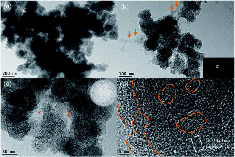
To obtain more microstructure and crystal structure information for the HM-30 powder after 1000 cycles, we obtained a detailed TEM analysis for the powder after 1000 cycles (Fig. 5). The results show that the whole electrode material is composed of uniform spheres, and a magnified TEM of the spheres reveals that some nanowire clusters were encapsulated within the spheres. The ultrathin nanowire was further verified to be Li2MoO4 from the HRTEM result, which agreed with the XRD results, as shown in Fig. 2 and 3. Interestingly, the possible mixed phase containing amorphous Mo and Li2O was not observed, which is similar to the results obtained in previous literature,39 while a SEI thin film and other amorphous parts were observed, which acted as a cage with the role of protecting the Li2MoO4 nanowires. The individual spheres show typical amorphous structural features, as confirmed by SAED, as shown in the inset of Fig. 5b. From the composition and structure analysis, it is similar to other materials. For another batch of the HM-30 sample, we also discovered the same structural feature in the HM-30 after 1000 cycles (Fig. S5†). A question arises from the robust gel-like thin film, how is it formed? Based on the unusual finding, we assumed that it may be the main reason for the increased capacity. This will be discussed further in Scheme 2.
When the HM-30 electrode materials were fully pulverized, questions arose as to whether the lithium-ion diffusion pathways and electronic conductive pathways were maintained and how the pulverized thin film increasingly boosted the LIB performance. To answer these questions, we carried out EIS measurements with different cycles at 500 mA g−1 and 2 A g−1 to provide more information. As shown in Fig. 6, the electrode indicates a lower resistance after the 10th and 100th cycles when compared with the new cell and the 1st cycle cell at 2 A g−1 (Fig. 6a). At the low current density of 500 mA g−1, the resistance decreases in a gradual way with the increasing number of cycles (Fig. 6b). Surprisingly, the resistance of the HM-30 electrode at 2 A g−1 is lower than that at 500 mA g−1. Furthermore, we also found that the wave shape cycling curves appeared after ca. 150 cycles (Fig. 4c). The results show that the robust film implied that it could maintain superior electric contact and lithium-ion transport characteristics during the long charge–discharge process, indicating its unique advantages for use as an anode material, especially in high-rate LIBs. In other words, the pulverized powder did not lead to an electronic contact loss of the intermediate phase of Li2MoO4. Instead, the thin film is very helpful in the increase of the capacity from the lithium insertion/desertion process. For the HM-30, the EIS results agree with the 1st discharge and charge capacity (Fig. S1†). The order of 1st capacity value for the HM-30 is 2 A g−1 > 1 A g−1 > 500 mA g−1. The 1st capacity value is higher than for other Mo-based anode materials, indicating that the HMs are a potential electrode candidate material for LIBs.
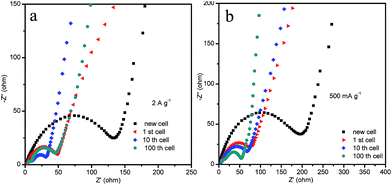 | ||
| Fig. 6 The Nyquist plots of EIS for the HM-30 electrodes for different cycles at 2 A g−1 and 500 mA g−1. | ||
The extraordinary long-life cycle stability may be attributed to the self-activated behaviour of the robust continuous pulverization film. Undoubtedly, the gel-like and slurry thin films played a critical role in enhancing the electrochemical properties of the HM-30. The ex situ FESEM and TEM of the pulverized powders upon lithium-ion insertion and extraction show that it eventually was closely linked. This also gave strong evidence for the continuous conductive pathways for lithium ion diffusion and electron transportation with long cycles. When the HM-30 was charged and discharged, the HM-30 was spontaneously transformed into a new phase, Li2MoO4 (Fig. 2b). From Fig. 2, it is obviously observed that those hollow Li2MoO4 nanotubes are interconnected with each other. This interconnected structure is very beneficial for the stability of LIBs. Surprisingly, this thin film structure is robust and stable even up to 1000 cycles. The powders are often pulverized and detached from the substrate due to great volume changes, however, in our case, the film is strongly attached onto the Cu substrate (Fig. S6†). Moreover, we also found that the original HM-30 powder itself is also readily shaped (Fig. S7†).
It is well-known that FTIR spectra have the ability to track molecular structure and composition changes, to gain some extra information from the powder composition, we carried out an ex situ FTIR analysis for the five points presented in Fig. S8.† The present work involves a lithium-ion battery electrolyte composition, which contains: (1) low-viscosity solvents like ethylene carbonate (EC); (2) LiPF6; (3) binder, semi-crystalline polymer, poly vinylidene fluoride (PVDF) and (4) organic solvent, 1-methyl-2-pyrrolidone (NMP). Therefore, the chemical reaction would be very complex and unknown between the electrode materials and electrolyte. It is extremely difficult to be certain how the reaction took place in more detail. For the HM-30 powders, the results show that the surface of the HM-30 still has three obvious OH, NH and C![[double bond, length as m-dash]](https://www.rsc.org/images/entities/char_e001.gif) C groups after hydrothermal treatment, corresponding to 3500,49 3200,50 and 1610 cm−1,51 respectively. It indicates that some remnants of PVP and formic acid are still adsorbed onto the surface of the HM-30. When discharged at 0.34 V, two new peaks of an unknown organic group occur at about 3420 and 1170 cm−1. Asymmetric and symmetric CH3 bending occurs at 1430 cm−1. This peak is present in all of the samples, indicating that the powder is surrounded by organic linker-like agents. Some remnants after the lithium-ion insertion and extraction also stayed on the surface of the pulverized powder even when the powder was washed by DMC. It is reasonably inferred that the robust film is mainly attributed to the following factors: (1) the existence of the PVP and formic acid on the HM-30 plays an important role during the chemical reaction between the HM-30 and electrolytes; (2) both the HM-30 and Li2MoO4 have a wide one-dimensional tunnel for insertion and extraction of the solvated lithium-ions (Scheme S2†). The robust film-like slurry was formed by a “vibration” effect of insertion–extraction in the lithium-ion batteries. It is hard to identify which functional group is from what matter, however, the remains of the organic matter still provide us with some key information to address how to interconnect each of the other pulverization particles.
C groups after hydrothermal treatment, corresponding to 3500,49 3200,50 and 1610 cm−1,51 respectively. It indicates that some remnants of PVP and formic acid are still adsorbed onto the surface of the HM-30. When discharged at 0.34 V, two new peaks of an unknown organic group occur at about 3420 and 1170 cm−1. Asymmetric and symmetric CH3 bending occurs at 1430 cm−1. This peak is present in all of the samples, indicating that the powder is surrounded by organic linker-like agents. Some remnants after the lithium-ion insertion and extraction also stayed on the surface of the pulverized powder even when the powder was washed by DMC. It is reasonably inferred that the robust film is mainly attributed to the following factors: (1) the existence of the PVP and formic acid on the HM-30 plays an important role during the chemical reaction between the HM-30 and electrolytes; (2) both the HM-30 and Li2MoO4 have a wide one-dimensional tunnel for insertion and extraction of the solvated lithium-ions (Scheme S2†). The robust film-like slurry was formed by a “vibration” effect of insertion–extraction in the lithium-ion batteries. It is hard to identify which functional group is from what matter, however, the remains of the organic matter still provide us with some key information to address how to interconnect each of the other pulverization particles.
Based on the above experimental results, a possible electrochemical mechanism is proposed to address the unique electrochemical behavior of the HM-30 (Scheme 2). Firstly, the HM-30 is easily transformed into Li2MoO4 due to the lithium-ion intercalation (Step I). Generally speaking, the lithium ions would easily penetrate into the one-dimensional tunnel with the solvated molecules of the electrolyte due to the wide tunnel. More importantly, the surface of the HM-30 contained a large amount of OH and PVP groups. During the charge–discharge process, the side reaction between the electrolyte and electrode surface easily produced the SEI thin film and some unknown organic compositions. In the complex system, PVP may act as a cross linking agent. Therefore, this would lead to the formation of the gel-like thin film. As time progressed, the as-formed Li2MoO4 nanotubes were further intercalated and gradually transformed into Li2MoO4 nanowire clusters by the lithium ions due to it containing a larger ion tunnel than in the HMs. Finally, it was evolved into ultrathin Li2MoO4 nanowire clusters within the Li2O, amorphous Mo and other unknown organic films (Step II). Without doubt, the large exposed surface area will provide more active sites for lithium ion diffusion and electron transfer. Moreover, the amorphous spheres acted as a carpet which was 50 nm in size (Fig. 5c), yielding fast strain relaxation for effective electron and lithium ion diffusion, thus achieving both an increased specific capacity growth with subsequent charge–discharge processes and high rate properties.
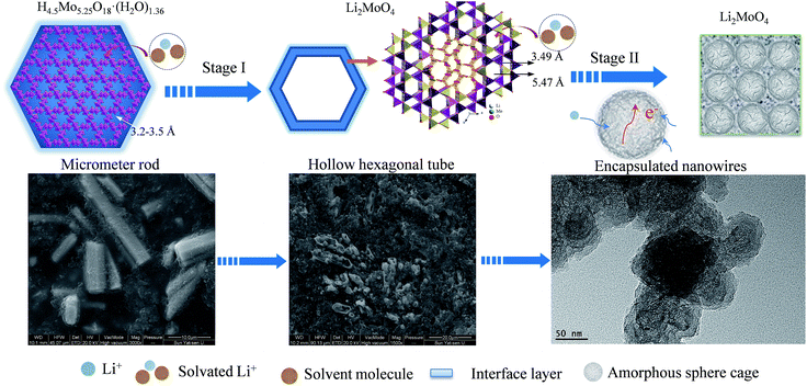 | ||
| Scheme 2 A schematic illustration of how the HM-30 was evolved into the Li2MoO4 nanowire clusters and amorphous spheres. The corresponding FESEM images are presented following Stage I and Stage II. | ||
Conclusions
In summary, a novel electrode material, HMs, has been synthesized for the first time using a simple one-pot hydrothermal method. When tested as an anode material for LIBs, the HMs indicate extraordinary long-life cyclability at a high current density of 2 A g−1. Moreover, the cycle stability performance of the HMs retains a specific capacity of 496 mA h g−1 even up to 1000 cycles without any capacity fading. The extraordinary long-life cyclability at high current densities should be attributed to the following points: (1) the pulverized powder generated a high specific surface area, which is favourable for lithium ion diffusion; (2) the robust gel-like thin film with amorphous sphere cages can effectively prohibit the aggregation of pulverization particles and reduces the strain due to the volume changes; (3) the ultrathin Li2MoO4 nanowire clusters formed by lithium ion insertion/desertion provide more active sites and reduce further pulverization upon lithium ion insertion–extraction. In contrast to the traditional method, the robust continuous gel-like pulverization film with a unique combination of amorphous sphere cages and an intermediate phase can effectively prohibit the mechanical and chemical pulverization of the LIB. One plausible “damage-reconstruction” model has been proposed to address the electrochemical behaviour of the HMs. The results reveal that the HMs are a great potential electrode material for LIBs in future applications. Importantly, the proposed model may also be extended to other anode materials for LIBs and provide a new strategy for high-performance LIBs from the perspective of pulverization.Acknowledgements
We gratefully acknowledge financial support from National Natural Science Foundation of China (No. 51462007, 41272064), and Guangxi Natural Science Foundation (No. 2014GXNSFAA118349, 2015GXNSFCA139018).References
- X. Yu, L. Wang, J. Liu and X. Sun, ChemElectroChem, 2014, 1, 1476–1479 CrossRef CAS.
- Y. Sun, J. Wang, B. Zhao, R. Cai, R. Ran and Z. Shao, J. Mater. Chem. A, 2013, 1, 4736–4746 CAS.
- J. Zhou, N. Lin, L. Wang, K. Zhang, Y. Zhu and Y. Qian, J. Mater. Chem. A, 2015, 3, 7463–7468 CAS.
- L. Zhou, L. Yang, P. Yuan, J. Zou, Y. Wu and C. Yu, J. Phys. Chem. C, 2010, 114, 21868–21872 CAS.
- P. Meduri, E. Clark, J. H. Kim, E. Dayalan, G. U. Sumanasekera and M. K. Sunkara, Nano Lett., 2012, 12, 1784–1788 CrossRef CAS PubMed.
- W. Shi and B. A. Lu, Electrochim. Acta, 2014, 133, 247–253 CrossRef CAS.
- R. Liu, D. Li, C. Wang, N. Li, Q. Li, X. Lu, J. S. Spendelow and G. Wu, Nano Energy, 2014, 6, 73–81 CrossRef CAS.
- H. Song, N. Li, H. Cui and C. Wang, Electrochim. Acta, 2014, 120, 46–51 CrossRef CAS.
- L. Shen, L. Yu, X. Y. Yu, X. Zhang and X. W. Lou, Angew. Chem., Int. Ed., 2015, 54, 1868–1872 CrossRef CAS PubMed.
- T. Li, X. Li, Z. Wang, H. Guo and Y. Li, J. Mater. Chem. A, 2015, 3, 11970–11975 CAS.
- Y. Chen, M. Zhuo, J. Deng, Z. Xu, Q. Li and T. Wang, J. Mater. Chem. A, 2014, 2, 4449–4456 CAS.
- J. Hwang, S. H. Woo, J. Shim, C. Jo, K. T. Lee and J. Lee, ACS Nano, 2013, 7, 1036–1044 CrossRef CAS PubMed.
- H. S. Im, Y. J. Cho, Y. R. Lim, C. S. Jung, D. M. Jang, J. Park, F. Shojaei and H. S. Kang, ACS Nano, 2013, 7, 11103–11111 CrossRef CAS PubMed.
- Y. H. Xu, Y. J. Zhu, Y. H. Liu and C. S. Wang, Adv. Energy Mater., 2013, 3, 128–133 CrossRef CAS.
- Y. Zhao, X. Li, B. Yan, D. Li, S. Lawes and X. Sun, J. Power Sources, 2015, 274, 869–884 CrossRef CAS.
- Y. Xu, X. Zhu, X. Zhou, X. Liu, Y. Liu, Z. Dai and J. Bao, J. Phys. Chem. C, 2014, 118, 28502–28508 CAS.
- M. Liu, X. Ma, L. Gan, Z. Xu, D. Zhu and L. Chen, J. Mater. Chem. A, 2014, 2, 17107–17114 CAS.
- W. Li, J. Zheng, T. Chen, T. Wang, X. Wang and X. Li, Chem. Commun., 2014, 50, 2052–2054 RSC.
- D. Lin, Z. Lu, P. C. Hsu, H. R. Lee, N. Liu, J. Zhao, H. Wang, C. Liu and Y. Cui, Energy Environ. Sci., 2015, 8, 2371–2376 CAS.
- M. T. McDowell, S. W. Lee, W. D. Nix and Y. Cui, Adv. Mater., 2013, 25, 4966–4984 CrossRef CAS PubMed.
- J. Zhu, C. Gladden, N. Liu, Y. Cui and X. Zhang, Phys. Chem. Chem. Phys., 2013, 15, 440–443 RSC.
- H. Pang, Y. Z. Zhang, W.-Y. Lai, Z. Hu and W. Huang, Nano Energy, 2015, 15, 303–312 CrossRef CAS.
- H. Pang, Y. Z. Zhang, Z. Run, W.-Y. Lai and W. Huang, Nano Energy, 2015, 17, 339–347 CrossRef CAS.
- Y. Z. Zhang, Y. Wang, T. Cheng, W.-Y. Lai, H. Pang and W. Huang, Chem. Soc. Rev., 2015, 44, 5181–5199 RSC.
- Y. Song, H. Wang, Z. Li, N. Ye, L. Wang and Y. Liu, Int. J. Hydrogen Energy, 2015, 40, 3613–3623 CrossRef CAS.
- J. Guo, P. Zavalij and M. S. Whittingham, J. Solid State Chem., 1995, 117, 323–332 CrossRef CAS.
- J. Kong, X. Yao, Y. Wei, C. Zhao, J. M. Ang and X. Lu, RSC Adv., 2015, 5, 13315–13323 RSC.
- N. Wang, H. Xu, L. Chen, X. Gu, J. Yang and Y. Qian, J. Power Sources, 2014, 247, 163–169 CrossRef CAS.
- M. L. Pang, J. Y. Hu and H. C. Zeng, J. Am. Chem. Soc., 2010, 132, 10771–10785 CrossRef CAS PubMed.
- R. Sharma and K. K. Kar, Electrochim. Acta, 2015, 156, 199–206 CrossRef CAS.
- H. S. Toh, K. Jurkschat and R. G. Compton, Chem.–Eur. J., 2015, 21, 2998–3004 CrossRef CAS PubMed.
- J. J. Lv, J. N. Zheng, H. B. Zhang, M. Lin, A. J. Wang, J. R. Chen and J. J. Feng, J. Power Sources, 2014, 269, 136–143 CrossRef CAS.
- J. J. Lv, J. N. Zheng, L. L. Chen, M. Lin, A. J. Wang, J. R. Chen and J. J. Feng, Electrochim. Acta, 2014, 143, 36–43 CrossRef CAS.
- J. Yang, T. Lan, J. Liu, Y. Song and M. Wei, Electrochim. Acta, 2013, 105, 489–495 CrossRef CAS.
- J. Shao, X. Li, Z. Wan, L. Zhang, Y. Ding, L. Zhang, Q. Qu and H. Zheng, ACS Appl. Mater. Interfaces, 2013, 5, 7671–7675 CAS.
- S. R. Popuri, M. Miclau, A. Artemenko, C. Labrugere, A. Villesuzanne and M. Pollet, Inorg. Chem., 2013, 52, 4780–4785 CrossRef CAS PubMed.
- Y. L. Cheah, V. Aravindan and S. Madhavi, ACS Appl. Mater. Interfaces, 2013, 5, 3475–3480 CAS.
- H. Wang, H. Yang and L. Lu, RSC Adv., 2014, 4, 43346–43350 RSC.
- L. Li, K. H. Seng, Z. Chen, Z. Guo and H. K. Liu, Nanoscale, 2013, 5, 1922–1928 RSC.
- K. M. Shaju, F. Jiao, A. Debart and P. G. Bruce, Phys. Chem. Chem. Phys., 2007, 9, 1837–1842 RSC.
- H. Sun, G. Xin, T. Hu, M. Yu, D. Shao, X. Sun and J. Lian, Nat. Commun., 2014, 5, 4526 CAS.
- X. Liu, Y. Lyu, Z. Zhang, H. Li, Y. Hu, Z. Wang, Y. Zhao, Q. Kuang, Y. Dong, Z. Liang, Q. Fan and L. Chen, Nanoscale, 2014, 6, 13660–13667 RSC.
- W. X. Ji, D. Wu, R. Yang, W. P. Ding and L. M. Peng, Chin. J. Inorg. Chem., 2015, 31, 659–665 CAS.
- L. A. Riley, S. H. Lee, L. Gedvilias and A. C. Dillon, J. Power Sources, 2010, 195, 588–592 CrossRef CAS.
- D. Mariotti, H. Lindstrom, A. C. Bose and K. Ostrikov, Nanotechnology, 2008, 19, 495302 CrossRef PubMed.
- L. Xiao, M. Schroeder, S. Kluge, A. Balducci, U. Hagemann, C. Schulzad and H. Wiggers, J. Mater. Chem. A, 2015, 3, 11566–11574 CAS.
- X. Li, Y. Ma, L. Qin, Z. Zhang, Z. Zhang, Y. Zheng and Y. Qu, J. Mater. Chem. A, 2015, 3, 2158–2165 CAS.
- J. Shen, H. Wang, Y. Zhou, N. Ye, G. Li and L. Wang, RSC Adv., 2012, 2, 9173–9178 RSC.
- C. Le Losq, G. D. Cody and B. O. Mysen, Am. Mineral., 2015, 100, 945–950 CrossRef.
- Y. Yan, T. Kuila, N. H. Kim, S. H. Lee and J. H. Lee, Carbon, 2015, 85, 60–71 CrossRef CAS.
- Y. Sun, Z. Fang, C. Wang, K. R. R. M. Ariyawansha, A. Zhou and H. Duan, Nanoscale, 2015, 7, 7790–7801 RSC.
Footnote |
| † Electronic supplementary information (ESI) available. See DOI: 10.1039/c5ta07314f |
| This journal is © The Royal Society of Chemistry 2016 |

