Fluoranthene derivatives as blue fluorescent materials for non-doped organic light-emitting diodes†
Shiv
Kumar
a,
Deepak
Kumar
a,
Yogesh
Patil‡
b and
Satish
Patil
*a
aSolid State and Structural Chemistry Unit, Indian Institute of Science, Bangalore 560012, India. E-mail: satish@sscu.iisc.ernet.in
bInorganic and Physical Chemistry, Indian Institute of Science, Bangalore 560012, India
First published on 17th November 2015
Abstract
In this study, we report synthesis of symmetrically and non-symmetrically functionalized fluoranthene-based blue fluorescent molecular materials for non-doped electroluminescent devices. The solid state structure of these fluorophores has been established by single crystal X-ray diffraction analysis. Furthermore, a detailed experimental and theoretical study has been performed to understand the effect of substitution of symmetric and non-symmetric functional groups on optical, thermal and electrochemical properties of fluoranthene. These materials exhibit a deep blue emission and high PLQY in solution and solid state. The vacuum deposited, non-doped electroluminescent devices with the device structure ITO/NPD (15 nm)/CBP (15 nm)/EML (40 nm)/TPBI (30 nm)/LiF (1 nm)/Al were fabricated and characterized. A systematic shift in the peak position of EL emission was observed from sky blue to bluish-green with EL maxima from 477 nm to 490 nm due to different functional groups on the periphery of fluoranthene. In addition, a high luminance of ≥2000 cd m−2 and encouraging external quantum efficiency (EQE) of 1.1–1.4% were achieved. A correlation of the molecular structure with device performance has been established.
Introduction
In 1963, Pope and co-workers reported the first observation of electroluminescence in anthracene single crystals at an applied dc voltage of more than 400 V across the two electrodes.1 However, organic light-emitting diodes (OLEDs) operating at such a high driving voltage were of no commercial use, but this work has stimulated a very intense topic of research in the field of OLEDs. Much effort has been made to understand the electroluminescence phenomena in organic crystals and fabrication of OLEDs for practical applications.2,3 In 1987, Tang and Van Slyke at Eastman Kodak successfully demonstrated a highly efficient electroluminescent device using an organic material operating at a voltage below 10 V; since then OLEDs have attracted considerable scientific and industrial interest.4 At present, numerous research groups and display manufacturing companies are working closely to develop OLED materials and technology for commercial applications such as flat-panel displays and solid-state lighting.5–7 In order to achieve a full-color display, it requires three primary colors, viz. blue, green and red; of equal efficiency, stability, and color purity.8 However, the achievement of stable and efficient blue emission is still challenging compared to green and red emission due to the requirement of wide band gap materials and high operating voltages.9 To obtain highly efficient OLEDs with low operational voltages, devices usually require complex configurations with several additional layers sandwiched between two electrodes to ease the charge injection and transport along with effective exciton confinement.10,11 In this regard, the blue OLED device fabrication process is tedious, complicated and exorbitant to compete with other flat-display technologies. In order to simplify the device configuration, many multifunctional materials have been developed possessing the characteristics such as high luminescence and charge injection/transporting properties.12,13 The utilization of such multifunctional materials and simplified device configurations may reduce the overall cost of OLEDs significantly.14 In addition, it has been observed that most of the blue fluorescent materials such as anthracene,15 fluorene,16 spiro,17 truxene,18 and pyrene19 show very high photoluminescence quantum yield (PLQY) in dilute solution, while their fluorescence gets significantly quenched in solid state due to self-aggregation. In order to avoid the aggregation effect, these fluorophores were used as guests in host matrices with optimized charge transport and luminescence properties in OLEDs.20 Such guest–host emitter doped systems not only improve the efficiency and operational stability of the devices by confining and transferring the electrical excitons to highly emissive and stable dopants in host matrices, but also minimize the undesired processes such as non-radiative pathways.21–23 Although the guest–host systems can improve the device efficiency significantly, but the intrinsic phase separation could deteriorate the performance severely during the operation.24 Such guest–host systems require suitable hosts which could confine the dopants effectively. The aforementioned limitations of guest–host emitter systems led to tremendous effort to circumvent these issues by using non-doped emitters in OLEDs.16,25,26 Intrigued by the good photoluminescence properties of the blue fluorophores in dilute solution, substantial effort has been devoted to develop deep-blue emitters with reduced fluorescence quenching in solid state. In pursuance of non-planar molecular structures with reduced inter-molecular interactions in solid state, various research groups used the strategy of introduction of rigid and bulky substituents such as phenyl, naphthyl, and tert-butyl groups at the periphery of the fluorophores. For example, Kwon et al. successfully introduced a rigid and bulky substituent such as tetraphenylsilane at the 9 and 10-positions of anthracene,27 and the resulting non-planar anthracene derivative not only exhibited the photophysical properties similar to pristine 9,10-diphenylanthracene (DPA) due to suppression of the intermolecular interactions in thin films and a short π-conjugation length, but also exhibited a high glass transition temperature (Tg). Along with anthracene, fluorene derivatives have been widely investigated and explored as deep blue emitting materials for OLEDs due to their high PLQYs and thermal stability.16 However, the green emission band observed in fluorene based OLEDs originates from fluorenone defects due to oxidation at the methane bridge and results in poor color purity and fluorescence quenching.28 Nevertheless, Wong et al. suggested a method of stabilizing the blue emission of polyfluorenes by the rational design and synthesis of ter(9,9-diarylfluorene), in which the C9-position was substituted by aryl substituents to impede the oxidation process.29Similar to fluorene family, fluoranthene is a very attractive fluorophore. The rigid planarized biphenyl structure of the fluoranthene unit leads to a wide band-gap with blue emission and also provides thermal and electrochemical stability. These properties make fluoranthene an interesting material for optoelectronics devices.30–33 Besides theoretical studies, enormous effort has been made to develop the facile synthesis of fluoranthene derivatives.34 The interesting properties such as a wide band gap, high PLQY, thermal and electrochemical stability make fluoranthene derivatives potential candidates for blue organic light-emitting diodes.35–41 By considering these advantages of fluoranthene, this work reports the design and synthesis of highly arylated, symmetrically and non-symmetrically functionalized fluoranthene derivatives for non-doped electroluminescent devices. By substituting different functional groups on the periphery of fluoranthene, we investigated differences in their solid-state packing and photophysical properties. The fluorophores were found to give deep-blue emissions with high fluorescent quantum yield. OLEDs fabricated using these materials were observed to deliver moderate external quantum efficiency with sky blue to bluish-green emission.
Results and discussion
Synthesis
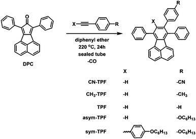
The general route for synthesis of fluoranthene derivatives is outlined in Scheme 1. The intermediate, 7,9-diphenyl-8H-cyclopenta[a]acenaphthylen-8-one (DPC), was synthesised by a double Knoevenagel condensation of 1,3-diphenylpropanone and acenaphthenequinone described by Walker et al. to form a dark-brown solid.42 Various symmetrically and non-symmetrically functionalized acetylene derivatives were synthesised by palladium-catalysed Sonogashira coupling reaction.43 The desired fluoranthene derivative was synthesized via the Diels–Alder cycloaddition reaction of acetylene derivatives with DPC in diphenyl ether as a solvent in sealed tubes. After removing diphenyl ether under reduced pressure, the resultant products were isolated by column chromatography in the quantitative yields of 60–70%. All the compounds were readily soluble in common organic solvents such as dichloromethane, chloroform, tetrahydrofuran, and toluene but sparingly soluble or insoluble in methanol and acetonitrile.Single crystal X-ray diffraction analysis
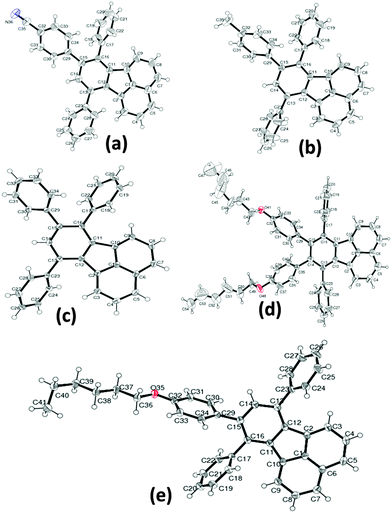
Several attempts were made to grow high quality crystals using various organic solvent mixtures for single crystal X-ray analysis. The single crystals for diffraction studies were obtained by the slow solvent evaporation method in dichloromethane/ethanol mixtures at ambient temperature. All the crystals were transparent in nature and bright greenish-yellow in color. The single crystal data were collected at room temperature unless mentioned otherwise. The crystal structures were established by subsequent refinement of the collected data and the crystal packing was analysed. All the compounds crystallized in the monoclinic space group P21/c, except for the compound asym-TPF which crystallized in the triclinic space group P1. The ORTEP diagrams of crystal structures are shown in Fig. 1. Since all the fluoranthene derivatives have a common fluoranthene core as the backbone with no conformational flexibility; the variations in structural arrangements observed in the solid state are purely governed by variations of the substituents on phenyl rings. Furthermore, the steric repulsion between aryl rings at the periphery of the fluoranthene unit prevented these compounds from adopting a planar structure. The degree of torsion angles between the fluoranthene unit and phenyl rings was influenced by the number of aryl substitutions. The crystal structure of non-symmetrically functionalized fluoranthene derivatives CN-TPF, TPF, and CH3-TPF were found to be isostructural but differ in molecular assembly and intermolecular interactions due to variations in functional groups on phenyl rings. The selective crystallographic details of all compounds are summarized in Table S1 (ESI†). The compound TPF without any functional group has been considered as the reference to compare the effect of functional groups on the molecular structure and the solid state packing of fluorophores. The presence of symmetric phenyl rings at C13 and C16 positions and an unsymmetrical phenyl ring at the C15 position of fluoranthene created large steric hindrance resulting in weak π–π interactions and variation in torsional angles.The structures vary in the torsional angles at C13, C16 and C15 positions (Table S2, ESI†). The supramolecular assembly was stabilized by C–H⋯π and C–H⋯N/O interactions as shown in Fig. S16 (ESI†). In addition, stacking has been observed in the case of CH3-TPF molecules. In the case of the sym-TPF structure, we observed the presence of diethyl ether and water in the crystal lattice. The structure was refined by squeezing these solvent molecules with PLATON squeeze. The refinement details are embedded in the CIF file.
Thermal properties
Thermal properties and stability of the compounds were investigated by differential scanning calorimetry (DSC) and thermogravimetric analysis (TGA). In DSC curves (Fig. 2), we observed that, these compounds exhibit an amorphous material behaviour except for CH3-TPF, which shows a crystalline nature. The thermal properties of these compounds can be corroborated with the molecular structure and various types of interactions in the solid state. For comparison, we considered TPF as the reference without any functional group at the periphery. In solid state, the molecules of the TPF compound were held together purely by C–H⋯π (2.685 Å) interactions, and therefore it exhibited an intermediate melting temperature (Tm) of 191 °C. In the case of the compound CN-TPF which showed a 44 °C higher Tm than the compound TPF, the molecules were stabilized by C–H⋯N interactions in addition to C–H⋯π interactions in solid state. The highest Tm of 260 °C and crystalline nature displayed by the compound CH3-TPF were attributed to the C–H⋯π and π⋯π stacking interactions among the neighbouring molecules. The compound asym-TPF showed a lower Tm than the compound TPF due to the presence of flexible hexylkoxy chains. The van der Waals interactions between hexylkoxy chains and C–H⋯O interactions held the molecules together in the solid state. The lowest Tm of 90 °C exhibited by the compound sym-TPF can be attributed to the presence of two flexible hexylkoxy chains. It was interesting to observe the splitting of the Tm peak in the DSC curves and this splitting may be due to first melting of the two flexible hexylkoxy chains followed by collapse of the self-assembly. From TGA curves (Fig. 2), all the compounds were found to be stable in the range 260–305 °C and the stability of the compounds strongly depended on the nature of the functional group at the periphery. The summary of the thermal properties is given in Table 2.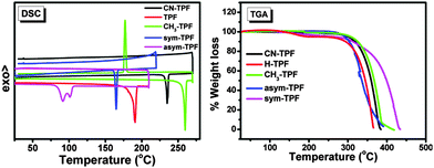 | ||
| Fig. 2 Thermal properties of fluoranthene derivatives. DSC trace (left), TGA thermogram (right) (scan rate 5 °C min−1). | ||
| Compound | E ox (V) | HOMO (eV) | E red (V) | LUMO (eV) | E g (eV) |
|---|---|---|---|---|---|
| CN-TPF | 1.48 | −6.03 | −1.78 | −2.77 | 3.26 |
| TPF | 1.40 | −5.95 | −1.77 | −2.78 | 3.17 |
| CH3-TPF | 1.40 | −5.95 | −1.67 | −2.88 | 3.07 |
| asym-TPF | 1.36 | −5.91 | −1.74 | −2.81 | 3.01 |
| sym-TPF | 1.22 | −5.77 | −1.78 | −2.77 | 3.00 |
| Compound | Solution | Neat film | E g (eV) | T m | T d | ||||||
|---|---|---|---|---|---|---|---|---|---|---|---|
| λ abs (nm) | λ em (nm) | τ (ns) | φ | λ abs (nm) | λ em (nm) | τ (ns) | φ | Film | (°C) | (°C) | |
| CN-TPF | 300, 329, 376 | 449 | 13 | 0.57 | 301, 329, 380 | 455 | 10 | 0.42 | 3.10 | 235 | 300 |
| TPF | 295, 329, 375 | 456 | 13 | 0.72 | 299, 329, 382 | 455 | 18 | 0.57 | 3.08 | 191 | 290 |
| CH3-TPF | 298, 329, 375 | 463 | 11 | 0.73 | 301, 329, 380 | 456 | 13 | 0.57 | 3.03 | 260 | 306 |
| asym-TPF | 300, 329, 377 | 464 | 9 | 0.80 | 304, 329, 382 | 467 | 12 | 0.65 | 3.01 | 165 | 290 |
| sym-TPF | 300, 329, 376 | 478 | 14 | 0.68 | 301, 329, 380 | 476 | 16 | 0.53 | 3.00 | 90 | 260 |
Electrochemical properties
The cyclic voltammograms of ferrocene and the studied compounds are shown in Fig. S17 (ESI†). The oxidation onsets of ferrocene, CN-TPF, TPF, CH3-TPF, asym-TPF, and sym-TPF were observed at 0.25 V, 1.48 V, 1.40 V, 1.40 V, 1.36 V, and 1.22 V, respectively, in their corresponding CV curves. A gradual decrease in the oxidation potential was observed from the compound CN-TPF to sym-TPF as the electron donating strength increased. All the compounds showed the irreversible oxidation cycle. In the case of the reduction cycle, compounds asym-TPF and sym-TPF showed a pseudo-reversible nature. The reduction onsets of CN-TPF, TPF, CH3-TPF, asym-TPF, and sym-TPF were observed at −1.78 V, −1.77 V, −1.67 V, −1.74 V, and 1.78 V, respectively. Hence, the calculated electrochemical band gap was found to be in the range 3.01–3.26 eV. The energy of HOMO and LUMO levels calculated with respect to the Fc/Fc+ couple is summarized in Table 1.Photophysical properties
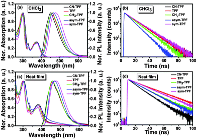
The photophysical properties of these compounds were studied using UV-visible absorption and fluorescence spectroscopy (Fig. 3(a) and (c)). In solution, the symmetrically and non-symmetrically functionalized compounds exhibited two well-resolved intense absorption bands at ∼300 ± 2 nm and ∼375 ± 2 nm and a well-resolved peak at 329 nm, as shown in Fig. 3(a), which is attributed to π→π* transitions. The weak absorption band at ∼375 nm exhibited a low oscillator strength with a broad shoulder at ∼425 nm. There was no significant shift observed in the position of absorption maxima for all the compounds, suggesting that phenyl rings substituted on the periphery of the fluoranthene core did not participate in the extension of the π-conjugation due to steric hindrance. This also implies that the influence of the functional group on ground state was negligible. However, a gradual red shift in emission peak was observed from 449 nm to 478 nm as the electron donating strength of the functional group increased from CN-TPF to sym-TPF. Further, this gradual shift was more pronounced in thin films. In neat films, a similar absorption pattern was observed with two well-resolved absorption bands at ∼300 ± 2 nm and ∼382 ± 2 nm along with broadening and a red shift of ∼5 nm of the absorption band at the longer wavelength as shown in Fig. 3(c). The appearance of a red shifted and broad absorption spectrum was due to strong intermolecular interactions and delocalization of π-electrons among the neighbouring molecules in the solid state. Like the emission in solution, the emission maxima varied from ∼455 nm to ∼475 nm for CN-TPF to sym-TPF. From the low energy onset of the absorption bands in neat films, the optical band gaps were calculated using the empirical equation (EOpticalg = 1240/λonset). The optical band gaps were found to be 3.0 eV and showed small variations, depending on the nature of substituents. The energy gap calculated from the absorption onset well corroborated with the experimental values estimated by CV, as discussed in the earlier section.The fluorescence quantum yields (Φs) of all the derivatives were in the ranges 0.57–0.80 and 0.42–0.65 in solution and neat films, respectively. High PLQY observed for all the derivatives in neat films can be attributed to their molecular structure and solid state packing. As shown in Fig. 1, the aryl rings at the periphery of the fluoranthene unit prevented these compounds from adopting a planar structure and underwent π–π stacking (Fig. S16, ESI†). Such a strategy has been utilized in an effective way to reduce concentration quenching in the fluorescent and phosphorescent dyes.44,45 The fluorescence lifetimes of these compounds in chloroform and neat films were measured by the time correlated single photon counting (TCSPC) method and were found to be in the ranges 9–14 ns and 10–18 ns, respectively (Fig. 3(b) and (d)). The longer fluorescence lifetime and decrease in PLQY in neat films are the evidence for aggregation quenching. The pertinent results of photophysical and fluorescence lifetime data on the effect of the functional group were analyzed and are summarized in Table 2.
Computational results
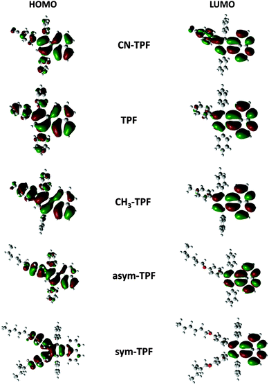
To analyze the electronic structures of fluoranthene derivatives, theoretical calculations were performed using density functional theory (DFT). It is well established that the energy levels of the frontier molecular orbitals, especially the HOMO and LUMO as well as their spatial distribution, play a very crucial role in determining the optical and electrochemical properties. In this regard, we employed DFT to optimize the ground state geometry using the M062X functional in conjunction with the 3-21G basis set. The extent of conjugation was assessed by electron density plots of the HOMO and LUMO of fluoranthene derivatives as shown in Fig. 4. The orbital diagrams are plotted with a contour value of 0.02 a.u. The plots of the HOMO and LUMO of the present molecule have the typical π molecular orbital characteristics. From the molecular orbital analysis, we infer that the lowest lying singlet–singlet absorption as well as emission corresponds to the π→π* transition. Fig. 4 illustrates that HOMO is delocalized while LUMO is localized on the fluoranthene core with a very significant electron density overlap. This electron density overlap explains the high PLQY of these compounds in solution and thin films. In the case of the sym-TPF compound, the HOMO is localized on the aryl substituents at 8,9-positions, whereas the LUMO is localized on the fluoranthene core similar to other compounds.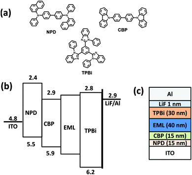 | ||
| Fig. 5 (a) Chemical structures of the materials used, (b) energy level diagrams, and (c) the device structure. | ||
Time-dependent DFT (TD-DFT) was employed to simulate the absorption spectra in gas phase and the excited state geometry was optimized at the M062X/3-21G level of theory. The simulated UV-visible spectra were found to be in very good agreement with the experimentally observed absorption spectra (Fig. S18, ESI†). The selected key electronic transitions are summarized in Table S3, ESI†.
Electroluminescence characteristics
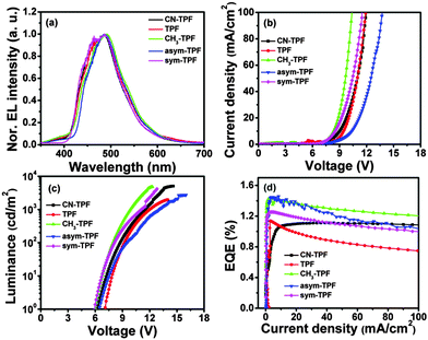
Electroluminescence characteristics were investigated by fabrication of a non-doped multilayer layer device comparing these compounds as the light emitting layer with the following device configuration: ITO/NPD (15 nm)/CBP (25 nm)/EML (40 nm)/TPBi (30 nm)/LiF (1 nm)/Al, where NPD is N,N′-di(1-naphthyl)-N,N′-diphenyl-(1,1′-biphenyl)-4,4′-diamine, CBP is 4,4′-bis(N-carbazolyl)-1,1′-biphenyl, and TPBi is 2,2′,2′′-(1,3,5-benzinetriyl)-tris(1-phenyl-1-H-benzimidazole), used as hole-injecting, hole-transporting and electron transporting layers, respectively. The chemical structure, energy level diagram and device architecture are shown in Fig. 5.Typical light emitting diode current density–voltage (J–V) and luminance–voltage (L–V) characteristics of fluoranthene based derivatives with the above-mentioned device structure are shown in Fig. 6(b) and (c), respectively. The turn-on voltage of the OLED was found to be 6.5 V, 7.3 V, 6.3 V, 6.8 V and 6.2 V with the maximum luminance of 5083 cd m−2, 1067 cd m−2, 4825 cd m−2, 2723 cd m−2, and 4148 cd m−2 for CN-TPF, TPF, CH3-TPF, asym-TPF, and sym-TPF, respectively. The plot of external quantum efficiency–current density (EQE–J) is shown in Fig. 6(d). All the devices showed the moderate EL performance with EQE in the range 1.1–1.4%. The CIE coordinates corresponding to EL spectra plotted in the chromaticity diagram and luminance efficiency–luminance (LE–L) plot are shown in Fig. S19 and S20 (ESI†), respectively. A red shift was observed in EL spectra when compared with PL spectra, suggesting that the emission takes place from the interface of hole transport layer and the emitting layer due to charge imbalance (Fig. 6(a)). The EL properties are summarized in Table 3.
| EML | EL (nm) | V on (V) | L max (cd m−2) | LE (cd A−1) | EQE (%) | CIE (x, y) |
|---|---|---|---|---|---|---|
| CN-TPF | 477 | 6.2 | 5083 | 1.31 | 1.10 | (0.13, 0.21) |
| TPF | 487 | 7.1 | 1967 | 1.39 | 1.15 | (0.13, 0.22) |
| CH3-TPF | 490 | 6.0 | 4825 | 1.79 | 1.45 | (0.13, 0.25) |
| asym-TPF | 487 | 6.2 | 2723 | 1.98 | 1.45 | (0.13, 0.26) |
| sym-TPF | 487 | 6.0 | 4148 | 1.59 | 1.25 | (0.13, 0.27) |
The device performance of fluorophores is strongly influenced by different functional groups. Compounds TPF, asym-TPF and sym-TPF show high efficiency roll-off, attributed to their low Tm and thermal stability. On the other hand, compounds CH3-TPF and CN-TPF do not exhibit efficiency roll-off of the EL device. The low EQE of compounds CN-TPF and TPF is attributed to their higher band gap (3.17 and 3.26 eV) and in particular CN-TPF also exhibits a low PLQY compared to other four compounds.
The performance of the devices is attributed to the improved photophysical properties in neat films due to functionalization of the fluoranthene core. The reduction in molecular aggregation and tuning of the molecular energy level have been achieved by substituents on the periphery on the fluoranthene core. The color purity and performance of the devices may be further improved by optimization of the device structure.
Experimental
Materials
1,3-Diphenyl-2-propanone, acenaphthenequinone, phenylacetylene, 4-iodobenzonitrile, 4-iodotoluene, 4-iodophenol, ethynyltrimethylsilane, and bis(triphenylphosphine)palladium(II) dichloride were purchased from Sigma-Aldrich Co. LLC and used as received without any further purification. Triethylamine was dried over sodium hydroxide prior to use. High pressure Teflon-coated sealed tubes were used for synthesis. Diphenyl ether was purchased from SD Fine-Chemicals Limited.Synthesis
All the fluoranthene derivatives were synthesized according to the scheme outlined in Scheme 1. The synthesis of different substituted diphenylacetylene derivatives and the desired fluoranthene derivatives is described in the ESI.†Characterization
The reaction products and their purity were confirmed using NMR spectroscopy, mass spectrometry and elemental analysis. 1H and 13C NMR spectra were recorded on Bruker 400 MHz and 100 MHz spectrometers, respectively, and calibrated using TMS as an internal reference. Chemical shifts were reported in parts per million (ppm). Mass spectra were recorded on a Thermo LCQ Deca XP Max by the electrospray ionization (ESI) technique. Elemental analysis was carried out on a Thermo Scientific Flash 2000 organic elemental analyzer. The UV-visible absorption spectra were obtained using a Perkin-Elmer (Lambda 35) UV-visible spectrometer. All the absorption spectra in the solution state were recorded in optical grade chloroform (conc. 1 × 10⁻⁵ M), and the spectra in solid state were recorded from films of compounds spin coated on quartz substrates. Steady-state fluorescence emission spectra were recorded on a Horiba Jobin-YvonFluoroLog-3 spectrometer. The transient PL decay characteristics were recorded using the time correlated single photon counting (TCSPC) method using a 365 nm LED on a Quantaurus-Tau fluorescence lifetime measurement system (C11367-03, Hamamatsu Photonics Co.). The fluorescence emission decay was well fitted by a single exponential decay profile. Absolute photoluminescence quantum yields (PLQY) were obtained using a Quantaurus-QY measurement system (C11347-11, Hamamatsu Photonics Co.). Single crystal X-ray diffraction data sets were collected on an Oxford Xcalibur (Mova) diffractometer equipped with an EOS CCD detector and Bruker D8Quest with a CMOS detector using Mo Kα radiation (λ = 0.71073 Å). The single crystal was maintained at the desired temperature during data collection using the Oxford instruments Cryojet-HT controller. All structures were solved by direct methods and refined using SHELXL-97.46 H-atoms were fixed geometrically and refined isotropically. The WinGX package was used for refinement and production of data tables along with ORTEP diagrams for structure visualization and molecular representation.47 Analysis of the H-bonding and π–π interactions were carried out using PLATON and packing diagrams were generated by using MERCURY.48 All quantum chemical calculations were carried out using Gaussian 09 Program by using the hybrid function M062X with the 3-21G basis set.49 Differential scanning calorimetry (DSC) analysis was carried out on a Mettler Toledo DSC1 STARe system (chiller cooled) with N2 flow of 40 mL min−1 with an empty Al pan taken as the standard. All samples were heated up at a heating rate of 5 °C min−1. Redox potentials were determined by the cyclic voltammetry (CV) experiment using a CH electrochemical analyser at a scanning rate of 50 mV s−1. Synthesized materials (0.2 mg/0.1 mL DCM) were drop cast on the working Pt disc electrode. Ag/AgCl was used as the reference electrode, whereas a Pt wire was employed as the counter electrode. Dry chloroform and 0.1 M tetrabutylammonium hexafluorophosphate were used as the solvent and supporting electrolyte, respectively. The ferrocene/ferrocenium (Fc/Fc+) (HOMO = −4.80 eV) couple was used as the standard electrochemical reference.50Conclusion
In summary, we have synthesized fluoranthene derivatives with various donor and acceptor substituents via the Diels–Alder reaction of 7,9-diphenyl-8H-cyclopenta[a]acenaphthylen-8-one with appropriate acetylene derivatives. The single crystal studies show various intermolecular interactions between the molecules and improved the understanding of the optical and thermal properties of this class of molecules. Computational studies further supported the experimental findings. Finally, the multilayer non-doped OLED devices were fabricated and sky blue to bluish-green color was observed. Our study presents a systematic approach for the molecular design to tune the color of fluoranthene-based derivatives.Conflict of interest
The authors declare no competing financial interest.Acknowledgements
We acknowledge Science and Engineering Research Board, Department of Science and Technology, for supporting this work through the project EMR/2015/000969. The authors thank Prof. Chihaya Adachi and Dr Qisheng Zhang for useful discussions and providing facility for OLED device fabrication and characterization. The authors also thank NMR Research Centre, IISc, for NMR facility. Shiv Kumar acknowledges Dr Sathya Perumal for useful discussions on the theoretical study and University Grant Commission (UGC) for a junior research fellowship (JRF).Notes and references
- M. Pope, H. Kallmann and P. Magnante, J. Chem. Phys., 1963, 38, 2042–2043 CrossRef CAS.
- W. Helfrich and W. Schneider, Phys. Rev. Lett., 1965, 14, 229 CrossRef CAS.
- W. Helfrich and W. Schneider, J. Chem. Phys., 1966, 44, 2902–2909 CrossRef CAS.
- C. W. Tang and S. Van Slyke, Appl. Phys. Lett., 1987, 51, 913–915 CrossRef CAS.
- K. T. Kamtekar, A. P. Monkman and M. R. Bryce, Adv. Mater., 2010, 22, 572–582 CrossRef CAS PubMed.
- G. M. Farinola and R. Ragni, Chem. Soc. Rev., 2011, 40, 3467–3482 RSC.
- H. Sasabe and J. Kido, J. Mater. Chem. C, 2013, 1, 1699–1707 RSC.
- P. E. Burrows, G. Gu, V. Bulovic, Z. Shen, S. R. Forrest and M. E. Thompson, IEEE Trans. Electron Devices, 1997, 44, 1188–1203 CrossRef CAS.
- Y.-H. Chung, L. Sheng, X. Xing, L. Zheng, M. Bian, Z. Chen, L. Xiao and Q. Gong, J. Mater. Chem. C, 2015, 3, 1794–1798 RSC.
- Y. J. Pu, G. Nakata, F. Satoh, H. Sasabe, D. Yokoyama and J. Kido, Adv. Mater., 2012, 24, 1765–1770 CrossRef CAS PubMed.
- S. Zhang, L. Yao, Q. Peng, W. Li, Y. Pan, R. Xiao, Y. Gao, C. Gu, Z. Wang, P. Lu, F. Li, S. Su, B. Yang and Y. Ma, Adv. Funct. Mater., 2015, 25, 1755–1762 CrossRef CAS.
- H. Xiao, L. Ding, D. Ruan, B. Li, N. Ding and D. Ma, Dyes Pigm., 2015, 121, 7–12 CrossRef CAS.
- C.-L. Liu, C.-J. Zheng, X.-K. Liu, Z. Chen, J.-P. Yang, F. Li, X.-M. Ou and X.-H. Zhang, J. Mater. Chem. C, 2015, 3, 1068–1076 RSC.
- G. Mallesham, C. Swetha, S. Niveditha, M. E. Mohanty, N. J. Babu, A. Kumar, K. Bhanuprakash and V. J. Rao, J. Mater. Chem. C, 2015, 3, 1208–1224 RSC.
- C. Adachi, T. Tsutsui and S. Saito, Appl. Phys. Lett., 1990, 56, 799–801 CrossRef CAS.
- S. Tao, Z. Peng, X. Zhang, P. Wang, C. S. Lee and S. T. Lee, Adv. Funct. Mater., 2005, 15, 1716–1721 CrossRef CAS.
- K. S. Kim, Y. M. Jeon, J. W. Kim, C. W. Lee and M. S. Gong, Org. Electron., 2008, 9, 797–804 CrossRef CAS.
- A. L. Kanibolotsky, R. Berridge, P. J. Skabara, I. F. Perepichka, D. D. Bradley and M. Koeberg, J. Am. Chem. Soc., 2004, 126, 13695–13702 CrossRef CAS PubMed.
- C. C. Yeh, M. T. Lee, H. H. Chen and C. H. Chen, in SID Symposium, 2004, p. 788.
- X. K. Liu, Z. Chen, C. J. Zheng, M. Chen, W. Liu, X. H. Zhang and C. S. Lee, Adv. Mater., 2015, 27, 2025–2030 CrossRef CAS PubMed.
- R. Holmes, B. D’Andrade, S. Forrest, X. Ren, J. Li and M. Thompson, Appl. Phys. Lett., 2003, 83, 3818–3820 CrossRef CAS.
- S. Tao, S. Xu and X. Zhang, Chem. Phys. Lett., 2006, 429, 622–627 CrossRef CAS.
- C. Adachi, M. A. Baldo, M. E. Thompson and S. R. Forrest, J. Appl. Phys., 2001, 90, 5048–5051 CrossRef CAS.
- Y.-C. Tsai and J.-H. Jou, Appl. Phys. Lett., 2006, 89, 243521 CrossRef.
- P. I. Shih, C. Y. Chuang, C. H. Chien, E. G. Diau and C. F. Shu, Adv. Funct. Mater., 2007, 17, 3141–3146 CrossRef CAS.
- J. Huang, N. Sun, J. Yang, R. Tang, Q. Li, D. Ma, J. Qin and Z. Li, J. Mater. Chem., 2012, 22, 12001–12007 RSC.
- Y. H. Kim, H. C. Jeong, S. H. Kim, K. Yang and S. K. Kwon, Adv. Funct. Mater., 2005, 15, 1799–1805 CrossRef CAS.
- E. J. List, R. Guentner, P. Scanducci de Freitas and U. Scherf, Adv. Mater., 2002, 14, 374–378 CrossRef CAS.
- K.-T. Wong, Y.-Y. Chien, R.-T. Chen, C.-F. Wang, Y.-T. Lin, H.-H. Chiang, P.-Y. Hsieh, C.-C. Wu, C. H. Chou and Y. O. Su, J. Am. Chem. Soc., 2002, 124, 11576–11577 CrossRef CAS PubMed.
- E. W. Thulstrup and J. Eggers, Chem. Phys. Lett., 1968, 1, 690–692 CrossRef CAS.
- I. B. Berlman, H. O. Wirth and O. Steingraber, J. Am. Chem. Soc., 1968, 90, 566–569 CrossRef CAS.
- B. Nickel, Chem. Phys. Lett., 1974, 27, 84–90 CrossRef CAS.
- X.-J. Li, M. Li, W. Yao, H.-Y. Lu, Y. Zhao and C.-F. Chen, RSC Adv., 2015, 5, 18609–18614 RSC.
- A. Goel, V. Kumar, S. Chaurasia, M. Rawat, R. Prasad and R. Anand, J. Org. Chem., 2010, 75, 3656–3662 CrossRef CAS PubMed.
- R. C. Chiechi, R. J. Tseng, F. Marchioni, Y. Yang and F. Wudl, Adv. Mater., 2006, 18, 325–328 CrossRef CAS.
- S. K. Kim, J. Y. Jaung and J. W. Park, Mol. Cryst. Liq. Cryst., 2008, 491, 122–132 CrossRef CAS.
- S. K. Kim and J. W. Park, J. Nanosci. Nanotechnol., 2008, 8, 4787–4792 CrossRef CAS PubMed.
- N. Kapoor and K. J. Thomas, New J. Chem., 2010, 34, 2739–2748 RSC.
- Y. H. Lee, T. C. Wu, C. W. Liaw, T. C. Wen, T. F. Guo and Y. T. Wu, J. Mater. Chem., 2012, 22, 11032–11038 RSC.
- Y. H. Lee, T. C. Wu, C. W. Liaw, T. C. Wen, S. W. Feng, J. J. Lee, Y. T. Wu and T. F. Guo, Org. Electron., 2013, 14, 1064–1072 CrossRef CAS.
- Y. Yuan, J.-X. Chen, F. Lu, Q.-X. Tong, Q.-D. Yang, H.-W. Mo, T.-W. Ng, F.-L. Wong, Z.-Q. Guo and J. Ye, Chem. Mater., 2013, 25, 4957–4965 CrossRef CAS.
- W. Walker, B. Veldman, R. Chiechi, S. Patil, M. Bendikov and F. Wudl, Macromolecules, 2008, 41, 7278–7280 CrossRef CAS.
- K. Sonogashira, Y. Tohda and N. Hagihara, Tetrahedron Lett., 1975, 16, 4467–4470 CrossRef.
- J. Shi and C. W. Tang, Appl. Phys. Lett., 2002, 80, 3201–3203 CrossRef CAS.
- H. Z. Xie, M. W. Liu, O. Y. Wang, X. H. Zhang, C. S. Lee, L. S. Hung, S. T. Lee, P. F. Teng, H. L. Kwong, H. Zheng and C. M. Che, Adv. Mater., 2001, 13, 1245–1248 CrossRef CAS.
- G. M. Sheldrick, Acta Crystallogr., Sect. A: Found. Crystallogr., 2007, 64, 112–122 CrossRef PubMed.
- L. J. Farrugia, J. Appl. Crystallogr., 1997, 30, 565 CrossRef CAS.
- L. J. Farrugia, J. Appl. Crystallogr., 1999, 32, 837–838 CrossRef CAS.
- M. J. Frisch, G. W. Trucks, H. B. Schlegel, G. E. Scuseria, M. A. Robb, J. R. Cheeseman, J. A. Montgomery, Jr., T. Vreven, K. N. Kudin, J. C. Burant, J. M. Millam, S. S. Iyengar, J. Tomasi, V. Barone, B. Mennucci, M. Cossi, G. Scalmani, N. Rega, G. A. Petersson, H. Nakatsuji, M. Hada, M. Ehara, K. Toyota, R. Fukuda, J. Hasegawa, M. Ishida, T. Nakajima, Y. Honda, O. Kitao, H. Nakai, M. Klene, X. Li, J. E. Knox, H. P. Hratchian, J. B. Cross, V. Bakken, C. Adamo, J. Jaramillo, R. Gomperts, R. E. Stratmann, O. Yazyev, A. J. Austin, R. Cammi, C. Pomelli, J. W. Ochterski, P. Y. Ayala, K. Morokuma, G. A. Voth, P. Salvador, J. J. Dannenberg, V. G. Zakrzewski, S. Dapprich, A. D. Daniels, M. C. Strain, O. Farkas, D. K. Malick, A. D. Rabuck, K. Raghavachari, J. B. Foresman, J. V. Ortiz, Q. Cui, A. G. Baboul, S. Clifford, J. Cioslowski, B. B. Stefanov, G. Liu, A. Liashenko, P. Piskorz, I. Komaromi, R. L. Martin, D. J. Fox, T. Keith, M. A. Al-Laham, C. Y. Peng, A. Nanayakkara, M. Challacombe, P. M. W. Gill, B. Johnson, W. Chen, M. W. Wong, C. Gonzalez and J. A. Pople, Gaussian 03, Revision C.02, Gaussian, Inc., Wallingford CT, 2008 Search PubMed.
- C. M. Cardona, W. Li, A. E. Kaifer, D. Stockdale and G. C. Bazan, Adv. Mater., 2011, 23, 2367–2371 CrossRef CAS PubMed.
Footnotes |
| † Electronic supplementary information (ESI) available: details of the synthetic procedures, 1H and 13C NMR, mass spectra, ORTEP diagrams, cyclic voltammograms and the summary of torsion angles. CCDC 965006, 965009, 965010, 1402234 and 1402235. For ESI and crystallographic data in CIF or other electronic format see DOI: 10.1039/c5tc02926k |
| ‡ Present address: Department of Chemistry, Central University of Karnataka, Kalaburagi 585367, Karnataka, India. |
| This journal is © The Royal Society of Chemistry 2016 |

