Improving the charge carrier transport of organic solar cells by incorporating a deep energy level molecule
Chunyu
Liu
a,
Zhiqi
Li
a,
Zhihui
Zhang
a,
Xinyuan
Zhang
a,
Liang
Shen
a,
Wenbin
Guo
*a,
Liu
Zhang
b,
Yongbing
Long
c and
Shengping
Ruan
*a
aState Key Laboratory on Integrated Optoelectronics, College of Electronic Science and Engineering, Jilin University, 2699 Qianjin Street, Changchun 130012, People's Republic of China. E-mail: guowb@jlu.edu.cn; ruansp@jlu.edu.cn
bCollege of Instrumentation & Electrical Engineering, Jilin University, 938 Ximinzhu Street, Changchun 130061, People's Republic of China
cSchool of Electronic Engineering, South China Agricultural University, Guangzhou, 510642, China
First published on 22nd November 2016
Abstract
Tetrafluoro-tetracyanoquinodimethane (F4-TCNQ), a strong molecular acceptor, has been proved to be an excellent candidate to achieve the p-type doping effect. When F4-TCNQ is incorporated into a poly(3-hexylthiophene) (P3HT): indene-C60 bisadduct (ICBA) active layer, superior behavior upon inducing polymer donor excited electron transport is demonstrated due to the addition of a deep-lying lowest unoccupied molecular orbital (LUMO) from F4-TCNQ, leading to the realization of organic solar cells (OSCs) with an improved power conversion efficiency (PCE) of 5.83%, accounting for 29.6% enhancement. In the system of active layer, the low LUMO of F4-TCNQ can easily accept electrons, remarkably reducing electron/hole recombination, which contributes to the enhancement of the photoconductivity and charge carrier mobility, resulting in higher short-circuit current density (Jsc), and achieving a more balanced charge carrier transport, as well as an ideal fill factor (FF).
1. Introduction
Currently, environmental pollution and energy shortage are the most severe challenges for human existence. The study of solar cells could solve these two problems effectively, and in the past few years, impressive progress has been made in solar energy, both in experimental research and market activity.1–4 Among the solar cells, organic solar cells (OSCs) have received much attention,5–7 although their power conversion energy (PCE) is still low for large-scale application. In the research of OSCs, poly(3-hexylthiophene) (P3HT) and indene-C60 bisadduct (ICBA) are excellent photovoltaic materials with the potential to obtain high open-circuit voltage (Voc) and fill factor (FF) when they are used to fabricate devices.8–11 ICBA is selected as the acceptor material by matching up P3HT electron donor instead of the typical fullerene acceptor (6,6)-phenyl C61 butyric acid methyl ester (PCBM); the main reason for this is that the deep-lying lowest unoccupied molecular orbital (LUMO) of ICBA (−3.7 eV) is much higher than that of PCBM (−4.3 eV), which will faithfully result in a higher Voc (exceeding 0.80 V).12–14 However, the devices with P3HT:ICBA generally demonstrate lower short-circuit current density (Jsc). Some methods should be put forward and applied to solve this problem from the aspects of optical properties and electronic characteristics.Intentional doping of the materials is necessary for improving performance of the organic photovoltaic devices,15–17e.g., for tunnelling contacts with efficient carrier injection and for the generation of space charge layers in p–n junctions.18,19 Studies on ternary solar cells have made a great deal of achievements with improved efficiency and they have been repeatedly reported on.20–23 Doping could also increase the quantity of charge carriers (electron or hole or both), leading to higher conductivity, which is important in many devices to lower the contact losses.24–28 Organic molecular materials (n-type and p-type) are promising for cell devices due to their adjustable and high absorption as well as electrical behaviour comparable to crystalline semiconductors in many respects. For instance, to achieve some improvement of holes, the p-type doping in organic layers with strong molecular acceptors like tetracyanoquinodimethane (TCNQ) or dicyano-dichloroquinone (DDQ) is necessary and has been proved to be a good idea to improve the performance of OSCs previously.29 In this work, we doped the tetrafluoro-tetracyanoquinodimethane (F4-TCNQ, C12N4F4, fluorinated form of TCNQ) into active layer fabricating devices with the structure of the ITO/polyethylenimine (PEI)/P3HT:ICBA:F4-TCNQ/WO3/Ag. F4-TCNQ is a strong molecular acceptor that possesses high electron affinity. Meanwhile, there are no molecular dopant clustering because charged F4-TCNQ anions will generate repulsion between each other at high coverage. Thus, efficient and stable p-doping will be achieved. Previously, F4-TCNQ has been also doped into carbon nanotube field-effect transistors leading to decrease in both the channel resistance and contact resistance by layer deposition of F4-TCNQ molecules.30 Meanwhile, Wee et al. has proved that F4-TCNQ is an excellent candidate for functionalizing graphene.31 In our study, the main purpose is to improve the lower Jsc of pristine P3HT:ICBA device, matching with its high Voc and FF to obtain the desired performance. We show that the incorporation of F4-TCNQ exhibits the following advantages: (1) increased photoconductivity and charge carrier mobilities due to the electrons from P3HT trapped by deep-lying LUMO of F4-TCNQ, reducing the electron/hole recombination, which contributes to the boost of Jsc, and (2) a more balanced charge carrier transport because of the apparent improvement of hole mobility, which benefits the enhanced FF. As a result, higher Jsc of 9.85 mA cm−2 and FF of 68.0% were achieved, resulting in an optimal PCE of 5.83% for the doped device with 0.10 wt% F4-TCNQ.
2. Experimental section
2.1. Device fabrication
F4-TCNQ was doped into an active layer and three different doping concentrations of 0.07 wt%, 0.10 wt% and 0.13 wt% (the weight ratio of F4-TCNQ to the total weights of P3HT and ICBA) were selected to improve the performance of the OSCs. The control device without F4-TCNQ was also fabricated using the same experimental parameters. Firstly, PEI solution with the concentration of 2 mg mL−1 was spin-coated onto the pre-cleaned ITO glasses, postannealing at 100 °C for 10 min. Then active layer solution including 15 mg P3HT and 15 mg ICBA in 1 mL 1,2-dichlorobenzene (DCB) was prepared. Different weights of F4-TCNQ were added to obtain doped active layer solutions. Well-blended active layer solutions were spin-coated onto the PEI layer at 1500 rpm for 30 s, annealing at 150 °C for 25 min in a glove box. Finally, WO3 (10 nm) and Ag (100 nm) were thermally evaporated as a hole transport layer and anode, respectively. Every active area of the OSC devices was about 0.064 cm2.2.2. Measurements and characterization
The film morphology was analyzed using a Bruker Dimension Icon Atomic Force Microscope (AFM). Current density–voltage (J–V) characteristics were measured using a Keithley 2601 source meter under 1 sun with an Oriel 300 W solar simulator intensity of ∼100 mW cm−2. The measurement of the incident photon-to-current efficiency (IPCE) was performed using a Crowntech QTest Station 1000 AD. The light absorption spectra were recorded on a UV 1700, Shimadzu. The impedance, Mott–Schottky curves and dark capacitance versus voltage (C–V) characteristics were analyzed by a Precision Impedance Analyzer 6500B Series of Wayne Kerr Electronics.3. Results and discussion
The chemical structure of F4-TCNQ and the energy diagram of the active layer materials are shown in Fig. 1(a) and (b), respectively. The LUMO of F4-TCNQ is ∼5.2 eV, deeper than that of the P3HT and ICBA, indicating that F4-TCNQ is a strong electron acceptor. In dark, when doping F4-TCNQ into the active layer, electrons from the highest occupied molecular orbital (HOMO) of the P3HT will preferentially occupy the deep-lying LUMO of the F4-TCNQ,32–34 which leads to an increase of the background hole concentration in the P3HT, contributing to the enhancement of the conductivity for doped devices.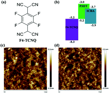 | ||
| Fig. 1 (a) Chemical structure of F4-TCNQ and (b) energy diagram of active layer materials, AFM morphology images of (c) pristine P3HT:ICBA film and (d) P3HT:ICBA:0.13 wt% F4-TCNQ hybrid film. | ||
The morphology of organic donor:acceptor thin films significantly influences exciton migration and dissociation,35–37 charge carrier transport,3,38 and charge carrier recombination,39–41 which is the major bottleneck that hampers the progress in PCEs of OSCs. Hence, the surface morphology of active layer films using AFM were measured firstly, shown in Fig. 1(c) and (d), including height images of P3HT:ICBA films without and with 0.13 wt% F4-TCNQ. There was an ignorable difference in average roughness of the surface between them (from 0.547 to 0.567 nm). Uniform surface morphology indicates that F4-TCNQ was evenly distributed in the active layer and there was no molecular clustering existence even for the highest doping concentration.
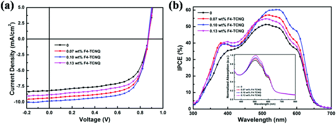
The comparison of J–V curves of devices without and with different concentration F4-TCNQ in Fig. 2(a) apparently indicates that Jsc was markedly improved by the incorporation of F4-TCNQ, leading to increased PCE for doped devices. The average photovoltaic parameters from thirty identical devices for each type are listed in Table 1. For the optimal doped device, the device with 0.10 wt% F4-TCNQ demonstrated higher PCE of 5.83% with increased Jsc (from 8.19 to 9.85 mA cm−2) and FF (from 63.2% to 68.0%), accounting for 29.6% enhancement in the PCE compared with the control device. When deviating from the optimal doping concentration, Jsc, FF and PCE began to decrease, while Voc remained at the same level. The performance of the device with higher doping concentration of 0.13 wt% began to decrease, which could have arisen from the decrease of the charge carrier mobilities. The effect of molecular doping on mobility rationally conforms to the analytic model of charge carrier mobility in doped organic semiconductors by D. Neher et al.,42 and the detailed charge carrier mobility would be calculated and compared in the subsequent works. Seen from Table 1, the Voc of all devices are about 0.87 V, which is the common performance for the solar cells based on P3HT:ICBA. The enhanced PCE of doped devices are mainly attributed to the increase of Jsc and FF, owing to the improved optical and electronic properties. Under illumination, the LUMO of F4-TCNQ could trap the electrons from P3HT, reducing the electron and hole recombination, which contributes to the increase of the photoconductivity and the charge carrier mobilities. Thus Jsc would be significantly improved and the more balanced charge carrier transport benefits the increased FF. In order to identify enhanced optical properties of doped devices arising from the existence of the F4-TCNQ, the IPCE curves for devices without and with F4-TCNQ were obtained and shown in Fig. 2(b). In the IPCE spectra, the 0.10 wt% F4-TCNQ device demonstrated a maximum IPCE of 60% at 530 nm, while the control device showed a maximum IPCE of 51% at 520 nm. Doped devices exhibited improved photon utilization in a wide wavelength range from 350 nm to 650 nm, being consistent with the enhanced light absorption range of active layers shown in the inset of Fig. 2(b).
| Doping concentration (wt%) | V oc (V) | J sc (mA cm−2) | FF (%) | PCE (%) | μ e (cm2 V−1 s−1) | μ h (cm2 V−1 s−1) | μ e/μh |
|---|---|---|---|---|---|---|---|
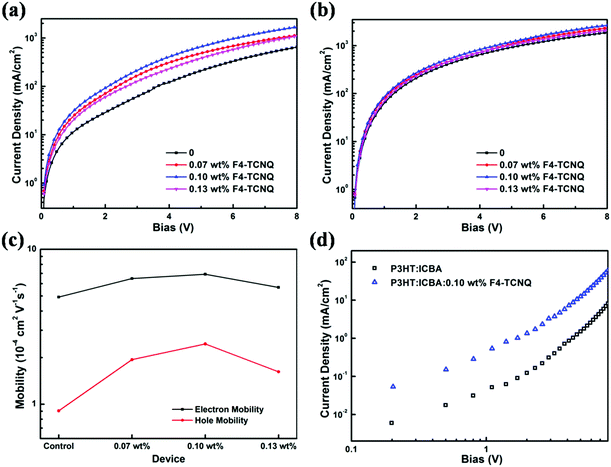
| 0 | 0.87 ± 0.01 | 8.19 ± 0.06 | 63.2 ± 0.2 | 4.50 ± 0.10 | 4.92 × 10⁻⁴ | 9.06 × 10⁻⁵ | 5.43 |
| 0.07 | 0.87 ± 0.01 | 9.36 ± 0.07 | 66.3 ± 0.1 | 5.40 ± 0.11 | 6.47 × 10⁻⁴ | 1.94 × 10⁻⁴ | 3.34 |
| 0.10 | 0.87 ± 0.01 | 9.85 ± 0.07 | 68.0 ± 0.1 | 5.83 ± 0.12 | 6.91 × 10⁻⁴ | 2.45 × 10⁻⁴ | 2.82 |
| 0.13 | 0.87 ± 0.01 | 8.84 ± 0.06 | 65.6 ± 0.2 | 5.05 ± 0.11 | 5.68 × 10⁻⁴ | 1.62 × 10⁻⁴ | 3.51 |
Under illumination, excited electrons in P3HT have a chance of jumping into the F4-TCNQ, trapped by the LUMO of the F4-TCNQ instead of being combined, which decreases the electron and hole recombination. In order to verify the existence of excited electron transport from P3HT to F4-TCNQ in the active layer, photoluminescence (PL) and time-resolved PL decay measurements were carried out. Fig. 3(a) is the PL spectra of neat P3HT:ICBA and P3HT:ICBA:0.10 wt% F4-TCNQ films. The PL intensity of the doped film is relatively lower than that of the neat P3HT:ICBA film, indicating that electron/hole recombination was apparently suppressed. Thus, part of the photo-generated electrons of P3HT were transferred to F4-TCNQ instead of being combined,43,44 which was further testified by the time-resolved PL decay measurements subsequently, shown in Fig. 3(b). It can be noted that the response of P3HT in the mixed film is shorter than that of the undoped film, suggesting the presence of an energy transfer process (i.e., electron transfer) from P3HT to F4-TCNQ.32,45–47 On this occasion, the charge carrier recombination in P3HT was reduced; therefore the hole concentration would be significantly increased, contributing to the improvement of electrical conductivity.
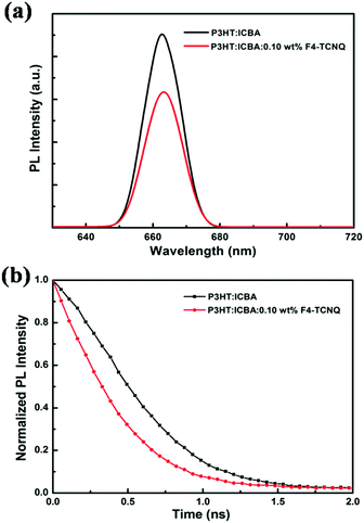 | ||
| Fig. 3 (a) PL spectra and (b) time-resolved PL decay curves of P3HT:ICBA films doped without and with 0.10 wt% F4-TCNQ. | ||
In order to calculate the quantity of charge carrier in devices, Mott–Schottky curves and dark C–V characteristics of the control device and optimal device were measured in a bias range of 0–1 V at 5 KHz. From Fig. 4(a) and (b), the built-in voltage (Vbi) and charge carrier density (n) of the P3HT:ICBA devices can be attained. According to the value of Vbi, n can be calculated based on
 | (1) |
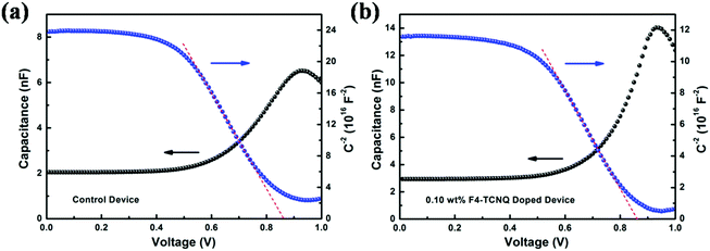 | ||
| Fig. 4 Mott–Schottky (blue line) and C–V (black line) curves of (a) control device and (b) doped device with 0.10 wt% F4-TCNQ. | ||
To investigate charge carrier transport balance, hole-only and electron-only devices were fabricated and the corresponding charge carrier mobilities were estimated. Firstly, hole-only devices with the structure of ITO/WO3/P3HT:ICBA:F4-TCNQ/WO3/Ag were fabricated, where WO3 is an electron blocking layer. Hole mobilities of all devices without and with F4-TCNQ were calculated by the charge transfer model of space-charge-limited-current (SCLC) and the Mott–Gurney law that includes field-dependent mobility,50,51 given by
 | (2) |
When F4-TCNQ was added into the active layer, the background hole concentration in polymer donor was increased due to the ground-state electron transport from P3HT to F4-TCNQ, which contributes to the improvement of the conductivity of doped devices. To examine the effect of this on resistance, the impedance spectroscopy was examined in the dark with an alternating current signal of 1 V in a frequency range of 20 Hz to 1 MHz, shown in Fig. 6. As we can see, the shapes of impedance spectra are desirable semicircles that are beneficial to investigate the resistance in OSCs. In the impedance spectroscopy, the diameters of the semicircles are connected with the series resistance (Rs). It is noteworthy that the diameters of the semicircles for these doped devices are smaller than those of the control device, which suggests decreased Rs, thus reducing the current losses across the contacting materials.52
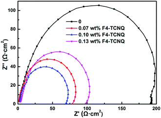 | ||
| Fig. 6 Impedance spectra of the devices without and with different concentrations of F4-TCNQ measured with a frequency range from 20 Hz to 1 MHz in dark. | ||
4. Conclusions
In summary, we deliberately doped F4-TCNQ with deep-lying LUMO into the active layer to induce excited electron transport, achieving p-type doping of P3HT:ICBA for optimized device performance resulting in a high PCE of 5.83%. The incorporation of F4-TCNQ could effectively decrease the electron/hole recombination and increase the charge carrier density. On the one hand, Jsc was effectively improved due to the increased photoconductivity. Meanwhile, impedance and Rs are significantly decreased, suppressing current loss, which also facilitates to increase Jsc. On the other hand, electron and hole transport became more balanced due to enhanced charge carrier mobilities, which is beneficial for improving FF.Acknowledgements
The authors are grateful to the National Natural Science Foundation of China (61275035, 61370046, and 11574110), the Opened Fund of the State Key Laboratory on Integrated Optoelectronics (IOSKL2013KF10), the Guangdong Natural Science Funds for Distinguished Young Scholar (Grant No. 2014A030306005), and the Foundation for High-level Talents in Higher Education of Guangdong Province, China (Yue Cai-Jiao [2013]246, Jiang Cai-Jiao[2014]10) for the support of the work.Notes and references
- M. Liu, M. B. Johnston and H. J. Snaith, Nature, 2013, 501, 395–398 CrossRef CAS PubMed.
- Y. He, J. Quan and G. Ouyang, Phys. Chem. Chem. Phys., 2016, 18, 7001–7006 RSC.
- W. Ma, C. Yang, X. Gong, K. Lee and A. J. Heeger, Adv. Funct. Mater., 2005, 15, 1617–1622 CrossRef CAS.
- K. S. Lee, J. A. Lee, B. A. Mazor and S. R. Forst, Light: Sci. Appl., 2015, 4, e288 CrossRef CAS.
- V. Vohra, K. Kawashima, T. Kakara, T. Koganezawa, I. Osaka, K. Takimiya and H. Murata, Nat. Photonics, 2015, 9, 403–408 CrossRef CAS.
- G. Williams, S. Sutty and H. Aziz, Phys. Chem. Chem. Phys., 2014, 16, 11398–11408 RSC.
- E. D. Kosten, J. H. Awater, J. Parsons, A. Polman and H. A. Awater, Light: Sci. Appl., 2013, 2, e45 CrossRef.
- W. Yu, L. Shen, Y. Long, P. Shen, W. Guo, W. Chen and S. Ruan, Org. Electron., 2014, 15, 470–477 CrossRef CAS.
- S. Gärtner, M. Christmann, S. Sankaran, H. Röhm, E. M. Prinz, F. Penth, A. Pütz, A. E. Türeli, B. Penth and B. Baumstümmler, Adv. Mater., 2014, 26, 6653–6657 CrossRef PubMed.
- C. F. Guo, T. S. Sun, F. Gao, Q. Liu and Z. F. Ren, Light: Sci. Appl., 2014, 3, e161 CrossRef.
- J. D. Chen, L. Zhou, Q. D. Ou, Y. Q. Li, S. Shen, S. T. Lee and J. X. Tang, Adv. Energy Mater., 2014, 4, 1301777 CrossRef.
- H. Li, Z. G. Zhang, Y. Li and J. Wang, Appl. Phys. Lett., 2012, 101, 163302 CrossRef.
- Y. He, H. Y. Chen, J. Hou and Y. Li, J. Am. Chem. Soc., 2010, 132, 1377–1382 CrossRef CAS PubMed.
- G. Zhao, Y. He and Y. Li, Adv. Mater., 2010, 22, 4355–4358 CrossRef CAS PubMed.
- J. Blochwitz, M. Pfeiffer, T. Fritz and K. Leo, Appl. Phys. Lett., 1998, 73, 729–731 CrossRef CAS.
- B. C. Park, S. H. Yun, C. Y. Cho, Y. C. Kim, J. C. Shin, H. G. Jeon, Y. H. Huh, I. C. Hwang, K. Y. Baik and Y. I. Lee, Light: Sci. Appl., 2014, 3, e222 CrossRef CAS.
- A. Yamamori, C. Adachi, T. Koyama and Y. Taniguchi, Appl. Phys. Lett., 1998, 72, 2147–2149 CrossRef CAS.
- E. L. Hanson, J. Guo, N. Koch, J. Schwartz and S. L. Bernasek, J. Am. Chem. Soc., 2005, 127, 10058–10062 CrossRef CAS PubMed.
- J. Blochwitz, T. Fritz, M. Pfeiffer, K. Leo, D. Alloway, P. Lee and N. R. Armstrong, Org. Electron., 2001, 2, 97–104 CrossRef CAS.
- M. Zhang, F. J. Zhang, Q. S. An, Q. Q. Sun, W. B. Wang, J. Zhang and W. H. Tang, Nano Energy, 2016, 22, 241–254 CrossRef CAS.
- Q. S. An, F. J. Zhang, Q. Q. Sun, M. Zhang, J. Zhang, W. H. Tang, X. X. Yin and Z. B. Deng, Nano Energy, 2016, 26, 180–191 CrossRef CAS.
- Q. S. An, F. J. Zhang, L. L. Li, J. Wang, Q. Q. Sun, J. Zhang, W. H. Tang and Z. B. Deng, ACS Appl. Mater. Interfaces, 2015, 7, 3691–3698 CAS.
- Q. S. An, F. J. Zhang, J. Zhang, W. H. Tang, Z. B. Deng and B. Hu, Energy Environ. Sci., 2016, 9, 281–322 Search PubMed.
- W. Gao and A. Kahn, Org. Electron., 2002, 3, 53–63 CrossRef CAS.
- B. Maennig, M. Pfeiffer, A. Nollau, X. Zhou, K. Leo and P. Simon, Phys. Rev. B: Condens. Matter Mater. Phys., 2001, 64, 195208 CrossRef.
- X. Chen, B. H. Jia, Y. A. Zhang and M. Gu, Light: Sci. Appl., 2013, 2, e92 CrossRef.
- Z. C. Holman, S. D. Wolf and C. Ballif, Light: Sci. Appl., 2013, 2, e106 CrossRef.
- Y. H. Su, Y. F. Ke, S. L. Cai and Q. Y. Yao, Light: Sci. Appl., 2012, 1, e14 CrossRef.
- N. El-Khatib, B. Boudjema, G. Guillaud, M. Maitrot and H. Chermette, J. Less-Common Met., 1988, 143, 101–112 CrossRef CAS.
- Y. Nosho, Y. Ohno, S. Kishimoto and T. Mizutani, Nanotechnology, 2007, 18, 415202 CrossRef.
- W. Chen, S. Chen, D. C. Qi, X. Y. Gao and A. T. S. Wee, J. Am. Chem. Soc., 2007, 129, 10418–10422 CrossRef CAS PubMed.
- X. Han, Z. Wu and B. Sun, Org. Electron., 2013, 14, 1116–1121 CrossRef CAS.
- X. Lei, F. Zhang, T. Song and B. Sun, Appl. Phys. Lett., 2011, 99, 233305 CrossRef.
- W. Gao and A. Kahn, J. Phys.: Condens. Matter, 2003, 15, S2757 CrossRef CAS.
- F. Gao and O. Inganas, Phys. Chem. Chem. Phys., 2014, 16, 20291–20304 RSC.
- L. M. Chen, Z. Hong, G. Li and Y. Yang, Adv. Mater., 2009, 21, 1434–1449 CrossRef CAS.
- J. Niklas, K. L. Mardis, B. P. Banks, G. M. Grooms, A. Sperlich, V. Dyakonov, S. Beaupre, M. Leclerc, T. Xu, L. Yu and O. G. Poluektov, Phys. Chem. Chem. Phys., 2013, 15, 9562–9574 RSC.
- P. Vanlaeke, A. Swinnen, I. Haeldermans, G. Vanhoyland, T. Aernouts, D. Cheyns, C. Deibel, J. D'Haen, P. Heremans and J. Poortmans, Sol. Energy Mater. Sol. Cells, 2006, 90, 2150–2158 CrossRef CAS.
- J. K. van Duren, X. Yang, J. Loos, C. W. Bulle-Lieuwma, A. B. Sieval, J. C. Hummelen and R. A. Janssen, Adv. Funct. Mater., 2004, 14, 425–434 CrossRef CAS.
- O. Blum and N. T. Shaked, Light: Sci. Appl., 2015, 4, e322 CrossRef CAS.
- D. Lepage, A. Jimenez, J. Beauvais and J. J. Dubowski, Light: Sci. Appl., 2012, 1, e28 CrossRef.
- P. Pingel, R. Schwarzl and D. Neher, Appl. Phys. Lett., 2012, 100, 143303 CrossRef.
- B. J. Moon, K. S. Lee, J. Shim, S. Park, S. H. Kim, S. Bae, M. Park, C. L. Lee, W. K. Choi and Y. Yi, Nano Energy, 2016, 20, 221–232 CrossRef CAS.
- L. Lu, T. Xu, W. Chen, J. M. Lee, Z. Luo, I. H. Jung, H. I. Park, S. O. Kim and L. Yu, Nano Lett., 2013, 13, 2365–2369 CrossRef CAS PubMed.
- L. Hou, L. Duan, J. Qiao, D. Zhang, G. Dong, L. Wang and Y. Qiu, Org. Electron., 2010, 11, 1344–1350 CrossRef CAS.
- V. Gupta, V. Bharti, M. Kumar, S. Chand and A. J. Heeger, Adv. Mater., 2015, 27, 4398–4404 CrossRef CAS PubMed.
- H. Choi, C. K. Mai, H.-B. Kim, J. Jeong, S. Song, G. C. Bazan, J. Y. Kim and A. J. Heeger, Nat. Commun., 2015, 6, 7348 CrossRef CAS PubMed.
- G. Garcia-Belmonte, A. Munar, E. M. Barea, J. Bisquert, I. Ugarte and R. Pacios, Org. Electron., 2008, 9, 847–851 CrossRef CAS.
- C. Shuttle, B. O'Regan, A. Ballantyne, J. Nelson, D. Bradley, J. De Mello and J. Durrant, Appl. Phys. Lett., 2008, 92, 3311 CrossRef.
- C. Goh, R. J. Kline, M. D. McGehee, E. N. Kadnikova and J. M. Fréchet, Appl. Phys. Lett., 2005, 86, 122110 CrossRef.
- X. C. Li, F. X. Xie, S. Q. Zhang, J. H. Hou and W. C. Choy, Light: Sci. Appl., 2015, 4, e273 CrossRef CAS.
- H. Zhou, Y. Zhang, J. Seifter, S. D. Collins, C. Luo, G. C. Bazan, T. Q. Nguyen and A. J. Heeger, Adv. Mater., 2013, 25, 1646–1652 CrossRef CAS PubMed.
| This journal is © the Owner Societies 2017 |

