Eco-fabrication of hierarchical porous silica monoliths by ice-templating of rice husk ash†
Amin
Bahrami‡
*ab,
Ulla
Simon
a,
Niloofar
Soltani‡
ab,
Sara
Zavareh
a,
Johannes
Schmidt
c,
Martin I.
Pech-Canul
b and
Aleksander
Gurlo
*a
aFachgebiet Keramische Werkstoffe/Chair of Advanced Ceramic Materials, Institut für Werkstoffwissenschaften und -technologien, Technische Universitaet Berlin, Hardenbergstraße 40, 10623 Berlin, Germany. E-mail: gurlo@ceramics.tu-berlin.de
bCentro de Investigación y de Estudios Avanzados del IPN Unidad Saltillo, Ave. Industria Metalúrgica No. 1062, Parque Industrial Saltillo-Ramos Arizpe, Ramos Arizpe, Coahuila, México 25900. E-mail: amin.bahrami@iim.unam.mx
cFachgebiet Funktionsmaterialien, Institut für Chemie, Sekr. BA 2, Technische Universität Berlin, Hardenbergstr. 40, 10623, Berlin, Germany
First published on 23rd November 2016
Abstract
In this study, within a sustainable chemistry approach, a clean and eco-friendly synthesis process of silica monoliths compatible with environmental limitations is developed. Rice husk (RH), a surplus agricultural byproduct, was used to engineer monoliths with a hierarchical pore structure. Amorphous and crystalline silica powders were extracted from rice husk and ice-templated using water as a liquid vehicle. The effect of silica crystallinity and silica content, as well as processing parameters such as the freezing rate and sintering temperature on the microstructural characteristics and mechanical properties of the obtained monoliths were investigated. Depending on the freezing regime, microstructural analysis confirmed the formation of macropores with lamellar or honeycomb-like structures. By varying the processing parameters, the pore size, wall thickness and porosity can be tailored. While monoliths from crystalline rice husk ash (CRHA) show higher mechanical strength, monoliths from amorphous rice husk ash (ARHA) possess a high specific surface area, demonstrating aligned nano-channels and non-uniform mesoporosity.
Introduction
Porous bulk ceramics are widely used for industrial applications such as liquid or gas filters, catalyst supports, gas distributors, porous anodes for high performance lithium-ion batteries, pre-forms for metal-impregnated ceramic metal composites and implantable bone scaffolds.1–4 Fabrication of porous ceramics normally involves the introduction of pores in the final materials during the preparation step by using a replica and sacrificial template, and by direct foaming and rapid-prototyping.5,6 Freeze-casting – also known as ice templating – is a sacrificial templating method in which a frozen liquid phase acts as a template for the pores. In a typical freeze-casting preparation route, a material of interest is dispersed in a liquid medium (e.g. water), which is frozen to form a solid (i.e. ice) before it is sublimated to yield a porous solid network that is a replica of the dispersing medium's frozen structure.7,8 A variety of porous ceramics including alumina, yttria-stabilised zirconia, titania, silicon nitride, mullite, magnesia, silica and silicon carbide have already been fabricated by the freeze-casting method.7,9–11 In the work of Li and Lu,12 both kaolinite platelets and silica nanorods were used for the fabrication of silica monoliths by the freeze-casting method. The maximum surface area obtained was 115 m2 g−1. Papa et al.,13 used metakaolin and fumed silica to fabricate geopolymer monoliths with controlled lamellar macroporosity and the surface area ranging from 33.4 to 39.4 m2 g−1, by ice-templating a partially geopolymerized slurry. By combining freeze-casting of freshly gelled hydrogels of sodium silicate and hydrothermal treatments with annealing at 600 °C or 900 °C, silica monoliths with surface areas of about 110–145 m2 g−1 were prepared.14Natural materials, in particular biomass, possess a chemical composition and structure that is not commonly found in synthetic materials. Rice husk, a form of biomass, is not only an energy source, but also a source for several value-added products such as silica, silicon and active carbon that can be extracted from rice husk under different treatment conditions.15 The leaching of rice husk with boiled solutions of HCl, H2SO4, H3PO4, HNO3, NH3xH2O and NaOH is effective in accelerating the hydrolysis of cellulose and hemicelluloses as well as in removing impurities such as Fe, K, Ca, Al, Mn, P, and S. This allows for producing completely white silica with a high specific surface area.15–19 The unique characteristics of rice husk ash such as high silica contents (which is typically in the range between 87 and 97 wt%), high porosity, lightweight and high specific surface area make it a valuable material for a variety of industrial applications, in comparison with other agricultural residues.20–25 Wang et al.,26 have synthesized biogenic silica nanoparticles (25–30 nm in diameter) from rice husk. The characterization revealed that the silica nanoparticles were composed of smaller primary particles (ca. 4.2 nm in diameter), and their clustering led to a porous structure with a surface area of 164 m2 g−1.
The objective of this work is to fabricate porous silica monoliths from rice husk ash while maintaining its unique porous properties. The eco-friendly freeze-casting method applied to rice husk ash yields hierarchical porous SiO2 monoliths suitable for applications such as adsorption, as catalyst supports and as porous ceramic preforms in the fabrication of metal or ceramic matrix composites. We discuss the influence of uni- and semidirectional freeze-casting methods on the pore structure of silica monoliths, compared to amorphous (ARHA) and crystalline (CRHA) rice husk ash derived materials and study the influence of sintering on their mechanical stability.
Results and discussion
Rice husk ash derived starting materials
Amorphous and crystalline rice husk ash (ARHA and CRHA, respectively) specimens are synthesized by calcination of acid-treated and intact rice husk according to the procedure recently reported by Bahrami et al. (for details see Table 1 and Table ESI-1 in the ESI†).23 In order to remove all organic compounds and increase the surface area, rice husk was calcined in air. Before processing, both CRHA and ARHA appear in the form of coiled and fragmented sheets and show the regular well-defined layered structure of the original rice husk with particle sizes in the submillimetre range (Fig. 1(a) and (b)). Chemical and thermal treatments remove the organic components of the rice husk leaving behind highly porous silica with a large specific surface area.22 Subsequent ball milling reduces the particle size to around 5–10 μm. TEM characterisation (Fig. 1(c) and (e)) shows that the ARHA consists of primary loose nanosized amorphous particles assembled in a secondary particle agglomerate that is surrounded by a hard shell. TEM images of CRHA (Fig. 1d and f) show that nanoscale crystalline silica particles form compact agglomerates of about 1 μm in size. This can be attributed to the lack of chemical treatment for the extraction of CRHA and higher temperature of heat treatment that facilitates crystallization processes, keeping the bonding between silica particles intact.15 The electron diffraction images are in line with the XRD results (Fig. ESI-1 and ESI-2 in the ESI†) confirming the amorphous and polymorphous crystalline SiO2 (low-tridymite and low-cristobalite) in the ARHA and CRHA specimens (insets in Fig. 1e and f), respectively.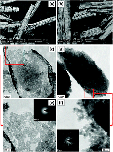 | ||
| Fig. 1 SEM (a and b) and TEM (c–f) micrographs of ARHA (a, c and e) and CRHA (b, d and f) powders. Insets in e and f show the electron diffraction pattern of the corresponding powders. | ||
| Material | Extraction method | Phase composition and structure | Density (g cm−3) |
|---|---|---|---|
| ARHA | Acid treatment and calcination at 600 °C in air | Amorphous | 1.6 |
| CRHA | Calcination at 900 °C in air | Crystalline (80 wt% low-cristobalite and 20 wt% low-tridymite) | 2.6 |
Fabrication of freeze-cast monoliths with lamellar and cellular pore structures
In this work, the influence of several fabrication parameters was assessed (for details, see Experimental) and the most suitable conditions were chosen for the fabrication of the ARHA- and CRHA-derived silica monoliths. For all processing parameters we succeeded to form freeze-cast structures (Fig. 2) with a dissimilar pore geometry and mechanical stability. It was found that the crystallinity of the starting RHA materials does not significantly affect the macropore structure of the fabricated monoliths, in contrast to processing parameters such as the freezing rate and the solid content.Based on the experimental design parameters and considering that some parameters have similar effects on the structure and properties of the specimens, the characterization of selected representative monoliths from each group is presented in the following sections.
Hierarchical porosity in the CRHA-derived SiO2 monoliths
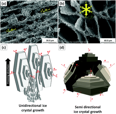
Firstly, unidirectional and semidirectional freeze-casting is compared. As these methods influence the microstructure of the ARHA- and CRHA-derived specimens in a similar way, we use the latter for discussion. Fig. 3 shows the pore structure of two different CRHA-derived samples, one frozen unidirectionally (Fig. 3a) and another semidirectionally (Fig. 3b), both after subsequent sublimation of water and burn-out of additives at 650 °C.In all unidirectionally frozen samples, the highly oriented pore structures formed parallel to the freezing direction. These unidirectionally channelled structures, called lamellar pore structures, were observed within the entire sample volume except for the side and bottom surfaces. They formed due to particle rejection from the growing ice crystal during freezing. Connection points between cells were also observed where ice crystals were in contact. In contrast, the semidirectional freeze-casting route leads to a honeycomb structure. Unlike other studies,27–29 dendritic structures were not observed.
This difference can be explained by the ice growth mechanisms in both freezing methods. At the first stage of solidification that occurs at the bottom of both samples, random orientation of numerous small ice crystals is observed. This is a very fast process due to large supercooling that leads to the entrapment of particles instead of repulsion, which in turn leads to the formation of dense structures without ordered pores. The difference lies in the unidirectional and semi-directional freezing conditions. For the former, a release of latent heat during ice crystallization causes a temperature increase in front of the ice crystals. This temperature increase is larger at the centre of the sample than at the bottom. This reduction in undercooling in the freezing direction decreases the driving force for nucleation, terminating the nucleation of ice crystals. Consequently, ice crystals with favourable growth axes start to grow parallel to the freezing direction in the middle zone of the sample (Fig. 3c).
The growth rate parallel to the crystallographic “c” axis in ice crystals is 102 to 103 times lower than that perpendicular to this axis.30 Therefore, anisotropic ice platelets grow very fast along the “a” axis (perpendicular to the freezing direction), while the thickness of these crystals along the “c” axis (parallel to the freezing direction) remains small. Such ice crystals continue to grow upward at the expense of the others leading to a frozen structure with long vertical lamellar ice crystals. In addition, particles are repelled by the growing ice crystals and pushed aside during freezing.
In the semidirectional freeze-casting method, the fast heat transfer from the metallic bottom with non-uniform temperature gradients allow ice crystals to grow in both “a” and “c” directions.31 In addition, the collision of ice platelets causes breakage of existing ice crystals and the nucleation and growth of new crystals that in turn results in a honeycomb structure (Fig. 3d).
Fig. 4 and 5 show the influence of the freezing rate and solid content on the final pore morphology in silica monoliths fabricated by unidirectional freeze-casting. As the trend is similar for all samples, selected ARHA and CRHA-derived SiO2 monoliths were chosen as examples.
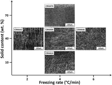 | ||
| Fig. 4 Effect of the freezing rate and solid content on the pore structure of CRHA-derived monoliths fabricated under different processing conditions. | ||
 | ||
| Fig. 5 Influence of the freezing rate and solid content on the pore structure of ARHA-derived monoliths fabricated by unidirectional freeze-casting: (a) ARHA12, (b) ARHA42, and (c) ARHA46. | ||
Fig. 4 shows the effect of the freezing rate as well as the solid content on the final pore morphology of the as-received monoliths for CRHA. All the fabricated samples show a similar oriented lamellar pore structure, however, the lamellar thickness and spacing are affected by the freezing rate. With the increasing freezing rate, faster solidification occurs resulting in a fine microstructure with a higher density of bridges between the ceramic walls. Such bridges are desirable because they significantly stiffen and strengthen the freeze-cast material.
The mean pore size and wall thickness decrease (10.3 to 2.5 μm) with increasing freezing rate from 2 to 6 °C min−1. In contrast, the walls become thicker and the pore size shrinks with an increase in solid content. This is due to the entrapment of a larger number of particles in the space between ice crystals.
Hierarchical porosity in ARHA-derived SiO2 monoliths
Fig. 5 shows the SEM micrographs of ARHA-derived monoliths with variations in the solid content and the freezing rate (ARHA12, ARHA42 and ARHA46 monoliths). In ARHA-derived monoliths, an increase in solid content causes an increase in wall thickness from 3.1 to 9.9 μm and a decrease in pore size (Fig. 5(a) and (b)). An increase in the freezing rate from 2 to 6 °C min−1 results in smaller pores and the wall thickness decreases from 9.9 to 5.6 μm (Fig. 5b and c).In addition to the macroporous features described above, the ARHA-derived monoliths possess meso- and microporosity. Fig. 6 shows the TEM images for one representative specimen (ARHA42) after the freeze-casting process (a, b) as well as after burning of the binder (c, d). This specimen shows oriented nanosized channels that were not observed in the starting ARHA material (compared to Fig. 1) and appeared only in the freeze-cast specimens. These nano-channels are formed in the direction of the temperature gradient indicating the directional growth of nanosized ice crystals inside the ARHA particles.
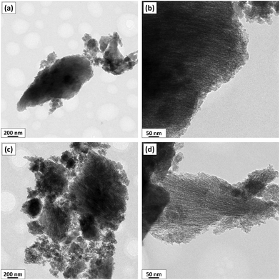 | ||
| Fig. 6 TEM micrographs of the ARHA42 specimen before (a, b) and after (c, d) binder removal. The images (c, d) display nano-channels inside the ARHA particles. | ||
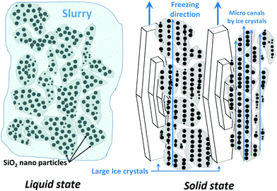
As demonstrated above (see Fig. 1), the μm-sized particles (secondary particles) in the ARHA specimens are agglomerates of primary nanosized amorphous silica particles surrounded by hard shells. As shown in Fig. 7, water molecules penetrate both between and inside the secondary silica particles so that the secondary as well as the primary silica particles are repelled during freezing by the growing ice crystals. The smaller (primary) particles form the walls of the nanochannels, while the larger (secondary) particles form the walls of the macropores during the sublimation step.
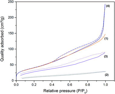
The surface area and pore volume of the starting ARHA powder and one of the freeze-cast monoliths before and after thermal removal of organic components were analysed by gas sorption analysis. Fig. 8 displays the nitrogen adsorption–desorption isotherms of these specimens.
The starting ARHA powder possesses a specific surface area (SBET) of 151 m2 g−1 and a total pore volume of 147 cm3 g−1. The shape of the isotherm indicates the presence of micropores and non-uniform mesopores. After freeze-casting and subsequent drying in a freeze-dryer, the SBET and total pore volume drop to 44 m2 g−1 and 29 cm3 g−1, respectively, due to the pore blocking caused by the organic additives added for slurry stabilization in the freeze-casting process.
After the thermal removal of these organic additives, the ARHA-derived silica monolith (ARHA44) possesses a SBET of 108 m2 g−1 and a total pore volume of 90 m2 g−1. After grinding the SBET is 157 m2 g−1, similar to that of the starting material, and the total pore volume is 243 cm3 g−1, which is significantly larger than the starting material. The latter is a result of macropores created during the freeze-casting process. The presence of macropores is confirmed by the shape of the adsorption isotherm, which indicates significant gas uptake at high relative pressures.
Compressive strength of CRHA-derived SiO2 monoliths
The effect of sintering was studied in CRHA-derived monoliths. Fig. 9 shows the SEM images of typical fractured surfaces of the CRHA44-monolith heat-treated at 650 °C and sintered at 1200, 1300 and 1400 °C for 2 hours. The walls in the specimens after removal of the binder at 650 °C consist of weakly bonded silica particles. This specimen has a porosity of 76%. Heat treatment at 1200 °C leads to partial sintering and grain growth (Fig. 9b); complete sintering of walls occurred in the whole monolith heat-treated at 1300 (Fig. 9c and e) and 1400 °C (Fig. 9d and f). The calculated open porosity is in the range of 75–85% and decreases with the sintering temperature. The specimens sintered at 1300 °C possess a higher density (2.74 g cm−3) than those sintered at 1200 (2.51 g cm−3) and 1400 °C (2.59 g cm−3) and those after binder removal at 650 °C (2.43 g cm−3).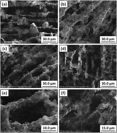 | ||
| Fig. 9 Effect of sintering temperature on the pore structure of C44 samples heat-treated at: (a) 650 °C, (b) 1200 °C, (c) and (e) 1300 °C, (d) and (f) 1400 °C. | ||
Sintering has a profound effect on the compressive strength of the RHA-derived monoliths (Fig. 10). First, all CRHA-derived monoliths have a higher compressive strength than those freeze-cast from ARHA under the same processing conditions (Fig. 10a). Since the connections between silica nanoparticles in ARHA are loose (see Fig. 1), the ARHA-derived monolith can barely stand the external load, being easily cracked and deformed. The partially sintered CRHA-derived monolith (after 1200 °C) is brittle and has a lower compressive strength than the green body with the organic binder (Fig. 10a). Sintering at 1300 and 1400 °C leads to an increase in the compressive strength to 2.2 MPa. Further increase in compressive strength is achieved in specimens with a higher solid content, mainly due to thicker walls and lower porosity (Fig. 10b).
Although the freezing rate has a significant effect on the porosity of the CRHA44 monolith, in directional frozen samples it cannot affect the mechanical properties and density of the monoliths dramatically (Fig. 10c). However, the compressive strength of semi-directionally frozen monoliths with a cellular pore structure is considerably higher than that of specimens with lamellar pores from the unidirectional freeze-casting process.31
For the latter, the initial cracks can easily propagate parallel to pore walls throughout the entire sample. In the semidirectionally frozen monoliths, proliferation of cracks is eased by curved pore walls (see Fig. 3b), which are stronger and more abundant than bridges between the pore walls, that in turn leads to high compressive strength.
Conclusions
Amorphous (ARHA) and crystalline (CRHA) silica monoliths were obtained from rice husk, a surplus agricultural by-product, by calcination of acid treated and intact rice husk, respectively. ARHA consists of silica nanoparticles held together by dense shells leading to micro- and non-uniform mesopores and a surface area of 151 m2 g−1 with a pore volume of 147 cm3 g−1. As a result of high temperature annealing, CRHA shows dense particles with a surface area of 1.5 m2 g−1 consisting of low-tridymite and low-cristobalite phases. Freeze-drying of water-based slurries was proven to be an effective forming process for the functionalization of ARHA and CRHA derived from rice husk by an environmentally friendly method (no organic solvents are needed) as well as fabricating tailored porous structures.Independent of the silica source, monoliths with an oriented lamellar pore structure were obtained due to the formation of ice crystals during directional freezing, while a honeycomb pore structure was formed when the slurry was frozen under semidirectional conditions. Increasing the solid content from 10 to 70 wt% causes an increase in the wall thickness from 3.1 to 9.9 μm for CRHA. Furthermore, an increase of the freezing rate from 2 to 6 °C min−1 results in the formation of a finer structure with thinner walls (5.6 μm) for CRHA.
Due to the unique physical structure of ARHA, which consists of primary silica nanoparticles arranged in μm-sized particles surrounded by hard shells, oriented nano-channels are formed during freeze-casting in addition to macropores. Freeze-casting of ARHA and thermal removal of organic compounds and crushing cause a significant increase in the pore volume (up to 243 cm3 g−1), due to the formation of macropores.
In contrast to ARHA-derived monoliths, CRHA-derived monoliths show higher compressive strength. An increase in the solid content as well as the sintering temperature above 1300 °C causes a significant increase in the compressive strength values of the fabricated monoliths.
This novel set of environmentally friendly starting materials and fabrication methods represents a versatile process to produce various porous components. While CRHA-derived macroporous monoliths have high strength (that is of interest e.g. for filters), the ARHA-derived monoliths with high specific surface areas possess additional meso- and microporosity that makes them suitable as catalyst supports and for sorption applications.
Experimental
The extraction procedure of ARHA and CRHA has been reported in detail elsewhere.22,23 The experimental procedure used in this study is summarised in the flowchart presented in Fig. 11. Rice husk ash powders were ground with a high energy planetary ball mill (PM4, Retsch) at position 12 for 20 min to produce a fine powder (d ≤ 10 μm). The suspensions for freeze-casting were prepared from ARHA and CRHA powders, dextrin from potato starch (Fluka®, Switzerland) and polyethylenimines (PEI, (C2H5N)n, MW 10.000, 99% purity, Polysciences PEI Inc.) as a binder and a dispersant respectively, then mixed with deionized water and ball-milled at position 12 for 15 min.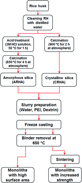 | ||
| Fig. 11 Flowchart of experimental procedure used for the fabrication of silica monoliths derived from rice husk ash. | ||
Table 2 summarises the experimental parameters varied in this study along with the abbreviations of the specimens. The nomenclature of monoliths was defined based on the type of silica (ARHA and CRHA), weight percentage of silica in the slurry (first number) and the freezing rate or condition (second number). The freeze-casting set-up used in this study is reported in ref. 32. It consists of a vessel with liquid nitrogen, protruding copper and brass rods for heat transfer, an acrylic glass mould and an additional heater with a thermocouple for controlling the freezing rate. After the freezing process, all samples were dried in a freeze-dryer (Christ Gamma 2 – 20, Martin Christ Gefriertrocknungsanlagen GmbH, Germany) at −30 °C under vacuum (0.03 mbar) for 3 days. PEI starts to decompose in air at 50 °C and under a nitrogen atmosphere at 300 °C.33,34 According to elemental analysis, the final monoliths contain less than 0.1 wt% of N as well as 0.15 wt% of C for CRHA and 1.1 wt% C for ARHA. Except for monoliths with 10 wt% solid, all the samples were heat treated at 650 °C in air for 2 h to remove organic components as well as PEI. In order to evaluate the effect of sintering temperature on the mechanical strength of fabricated monoliths, C44 samples were sintered at 1200, 1300 and 1400 °C in air for 2 h.
| RHA crystallinity | Solid content (wt%) | Dextrin (wt%) | PEIa (wt%) | Freezing rate (°C min−1) | Sample name |
|---|---|---|---|---|---|
| a 20 wt% PEI solution. b Semi-directional. c Slurry preparation was failed because of the high surface of ARHA. | |||||
| ARHA | 10 | 10 | 1 | 2 | ARHA12 |
| 4 | ARHA14 | ||||
| 6 | ARHA16 | ||||
| SDb | ARHA1SD | ||||
| 40 | 5 | 1 | 2 | ARHA42 | |
| 4 | ARHA44 | ||||
| 6 | ARHA46 | ||||
| SDb | ARHA4SD | ||||
| 70 | 2 | 1 | 2 | ARHA72c | |
| 4 | ARHA74c | ||||
| 6 | ARHA76c | ||||
| SDb | ARHA7SDc | ||||
| CRHA | 10 | 10 | 1 | 2 | CRHA12 |
| 4 | CRHA14 | ||||
| 6 | CRHA16 | ||||
| SDb | CRHA1SD | ||||
| 40 | 5 | 1 | 2 | CRHA42 | |
| 4 | CRHA44 | ||||
| 6 | CRHA46 | ||||
| SDb | CRHA4SD | ||||
| 70 | 2 | 1 | 2 | CRHA72 | |
| 4 | CRHA74 | ||||
| 6 | CRHA76 | ||||
| SDb | CRHA7SD | ||||
In all heat treatment procedures, the samples were heated with a low heating rate of 1 °C min−1 to avoid cracking of monoliths. In contrast to the CRHA-derived samples, the freeze-casting of slurries with 70 wt% solid content of ARHA failed due to their high viscosity, which was caused by high surface area. As a result, such pastes could not be cast into the mould.
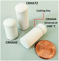
The microstructure of the starting materials as well as the fabricated monoliths was characterized by scanning electron microscopy (SEM, Hitachi SU8030), transmission electron microscopy (TEM, TECNAI G220 S-TWIN), thermal analysis (TG-DTA, STA 429, Netzsch, Germany) and nuclear magnetic resonance spectroscopy (NMR, Bruker Avance II 400 MHz NMR spectrometer). The samples for SEM characterization were cut from the top of the monoliths as can be seen in Fig. 2. The specimens were then placed upside down in a dry ultrasonic cleaner bath for 60 seconds to remove broken and loose particles from the fractured surface. The samples for TEM characterization were partially crushed to reveal the meso- and microporosity of powders.
X-ray diffraction (XRD) patterns were recorded by employing Cu Kα radiation (λ = 1.54 Å) in the 2θ range of 10–80°, using a scan step of 0.03°, a voltage of 40 kV, and a current of 30 mA, on the powdered samples. The total porosity and true density of the samples were assessed by He pycnometry (Micromeritics 1305, Norcross, Georgia, USA). Compression tests were done according to ASTM C1674-11 in Z020 equipped with AST-sensors and testXpert v. 11 software (Zwick/Roell, Germany) on cylindrical monoliths (length: 15 mm, diameter: 10 mm).
Nitrogen sorption isotherms were obtained at −196 °C using a QuadraSorb SI volumetric analyser (Quantachrome Instruments). Prior to measurement, the samples were degassed at least at 120 °C for 10 h (10−3 mbar). The organic–inorganic composite after the freeze-casting and drying process was degassed at 50 °C for 24 h and measured as the whole monolith. The specific surface area (SBET) was calculated from the Brunauer–Emmett–Teller (BET) model from the adsorption branch of the isotherms; the pore volume was determined at 0.99 p/p0.
Rice husk, ARHA and CRHA were analysed by semiquantitative X-Ray Fluorescence Spectrometry (XRF) with a S4 PIONEER (Bruker, Germany) with an excitation source of 4 kW. The interpretation of the data was performed using the SPECTRA plus software.
Acknowledgements
Mr Amin Bahrami and Ms Niloofar Soltani gratefully acknowledge CONACyT (National Council of Science and Technology, Mexico) for granting an academic stay at the Technische Universität Berlin, Berlin, Germany. The authors are also thankful to Mr Soeren Selve and Mr Ulrich Gernert (ZELMI, Technische Universität Berlin) for TEM and SEM characterisation and Dr Jan-Dirk Epping and Christina Eischenauer for NMR and nitrogen sorption measurements respectively (all at Technische Universität Berlin). Ulla Simon and Aleksander Gurlo thank the Cluster of Excellence “Unifying Concepts in Catalysis” for funding. The project was financed by the German Research Foundation (DFG – Deutsche Forschungsgemeinschaft).References
- K. Araki and J. W. Halloran, J. Am. Ceram. Soc., 2005, 88, 1108–1114 CrossRef CAS.
- J. Ou, Y. Zhang, L. Chen, Y. Guo and D. Xiao, Ionics, 2015, 21, 1881–1891 CrossRef CAS.
- S. Verma, M. Nandi, A. Modak, S. L. Jain and A. Bhaumik, Adv. Synth. Catal., 2011, 353, 1897–1902 CrossRef CAS.
- C. Gerardin, J. Reboul, M. Bonne and B. Lebeau, Chem. Soc. Rev., 2013, 42, 4217–4255 RSC.
- H. Zhang, P. D'Angelo Nunes, M. Wilhelm and K. Rezwan, J. Eur. Ceram. Soc., 2016, 36, 51–58 CrossRef CAS.
- E. C. Hammel, O. L. R. Ighodaro and O. I. Okoli, Ceram. Int., 2014, 40, 15351–15370 CrossRef CAS.
- S. Deville, Adv. Eng. Mater., 2008, 10, 155–169 CrossRef CAS.
- M. Naviroj, S. M. Miller, P. Colombo and K. T. Faber, J. Eur. Ceram. Soc., 2015, 35, 2225–2232 CrossRef CAS.
- T. Fukasawa, M. Ando, T. Ohji and S. Kanzaki, J. Am. Ceram. Soc., 2001, 84, 230–232 CrossRef CAS.
- K. Araki and J. W. Halloran, J. Am. Ceram. Soc., 2004, 87, 2014–2019 CrossRef CAS.
- T. Fukasawa, Z. Y. Deng, M. Ando, T. Ohji and S. Kanzaki, J. Am. Ceram. Soc., 2002, 85, 2151–2155 CrossRef CAS.
- W. Li, K. Lu and J. Y. Walz, J. Am. Ceram. Soc., 2011, 94, 1256–1264 CrossRef CAS.
- E. Papa, V. Medri, P. Benito, A. Vaccari, S. Bugani, J. Jaroszewicz and E. Landi, RSC Adv., 2016, 6, 24635–24644 RSC.
- H. Nishihara, S. R. Mukai, D. Yamashita and H. Tamon, Chem. Mater., 2005, 17, 683–689 CrossRef CAS.
- N. Soltani, A. Bahrami, M. I. Pech-Canul and L. A. González, Chem. Eng. J., 2015, 264, 899–935 CrossRef CAS.
- C. Real, M. D. Alcalá and J. M. Criado, J. Am. Ceram. Soc., 1996, 79, 2012–2016 CrossRef CAS.
- A. Chakraverty, P. Mishra and H. D. Banerjee, J. Mater. Sci., 1988, 23, 21–24 CrossRef CAS.
- V. B. Carmona, R. M. Oliveira, W. T. L. Silva, L. H. C. Mattoso and J. M. Marconcini, Ind. Crops Prod., 2013, 43, 291–296 CrossRef CAS.
- U. Kalapathy, A. Proctor and J. Shultz, Bioresour. Technol., 2000, 73, 257–262 CrossRef CAS.
- M. N. Amin, S. Kaneco, T. Kitagawa, A. Begum, H. Katsumata, T. Suzuki and K. Ohta, Ind. Eng. Chem. Res., 2006, 45, 8105–8110 CrossRef CAS.
- L.-H. Wang and C.-I. Lin, J. Chin. Inst. Chem. Eng., 2008, 39, 367–373 CrossRef CAS.
- A. Bahrami, M. I. Pech-Canul, C. A. Gutierrez and N. Soltani, J. Alloys Compd., 2015, 644, 256–266 CrossRef CAS.
- A. Bahrami, M. I. Pech-Canul, C. A. Gutiérrez and N. Soltani, Appl. Surf. Sci., 2015, 357(Part A), 1104–1113 CrossRef CAS.
- A. Bahrami, N. Soltani, M. I. Pech-Canul and C. A. Gutiérrez, Crit. Rev. Environ. Sci. Technol., 2016, 46, 143–208 CrossRef.
- A. Proctor, J. Am. Oil Chem. Soc., 1990, 67, 576–584 CrossRef CAS.
- W. Wang, J. C. Martin, X. Fan, A. Han, Z. Luo and L. Sun, ACS Appl. Mater. Interfaces, 2012, 4, 977–981 CAS.
- S. Ding, Y. P. Zeng and D. Jiang, J. Am. Ceram. Soc., 2007, 90, 2276–2279 CrossRef CAS.
- M. Fukushima, M. Nakata, Y. Zhou, T. Ohji and Y.-i. Yoshizawa, J. Eur. Ceram. Soc., 2010, 30, 2889–2896 CrossRef CAS.
- T. Fukasawa, Z. Y. Deng, M. Ando, T. Ohji and S. Kanzaki, J. Am. Ceram. Soc., 2002, 85, 2151–2155 CrossRef CAS.
- S. Deville, E. Saiz and A. P. Tomsia, Acta Mater., 2007, 55, 1965–1974 CrossRef CAS.
- P. M. Hunger, A. E. Donius and U. G. K. Wegst, Acta Biomater., 2013, 9, 6338–6348 CrossRef CAS PubMed.
- S. Zavareh, A. Hilger, K. Hirselandt, O. Goerke, I. Manke, J. Banhart and A. Gurlo, J. Ceram. Soc. Jpn., 2016, 124, 1067–1071 CrossRef.
- V. V. Nedel'ko, B. L. Korsunskii, F. I. Dubovitskii and G. L. Gromova, Polym. Sci. U.S.S.R., 1975, 17, 1697–1703 CrossRef.
- L. E. Davis, Polyethyleneimine, in Water-Soluble Resins, ed. R. L. Davidson and M. Sittig, Van Nostrand Reinhold, New York, 2nd edn, 1968 Search PubMed.
Footnotes |
| † Electronic supplementary information (ESI) available. See DOI: 10.1039/c6gc02153k |
| ‡ These authors contributed equally to this work. |
| This journal is © The Royal Society of Chemistry 2017 |

