DOI:
10.1039/C6RA26356A
(Paper)
RSC Adv., 2017,
7, 433-448
Chelating magnetic nanocomposite for the rapid removal of Pb(II) ions from aqueous solutions: characterization, kinetic, isotherm and thermodynamic studies
Received
5th November 2016
, Accepted 16th November 2016
First published on 3rd January 2017
Abstract
In this study, a Fe3O4@GMA–AAm magnetic nanocomposite was synthesized as a novel adsorbent with a suitable core–shell structure, high adsorption capacity (158.73 mg g−1), easy separation and rapid adsorption rate. For this purpose, Fe3O4 NPs were first reacted with 3-aminopropyltriethoxysilane for the preparation of MNPs–NH2. Then the MNPs–NH2 was allowed to react with glycidylmethacrylate to form Fe3O4–GMA. Finally Fe3O4@GMA–AAm was synthesized by grafting polyacrylamide onto the Fe3O4–GMA using a radical polymerization process. The morphology and characteristics of the adsorbent were examined by various techniques such as FT-IR, TEM, SEM, XRD, AFM, TGA, EDX, EMA and VSM analysis. The synthesized adsorbent was used for the removal of Pb2+ ions from aqueous media and the effect of different parameters (pH, adsorbed dosage, temperature, etc.) was investigated. The isotherm analysis indicated that the adsorption experimental data fitted very well with the Langmuir isotherm model. Two kinetics equations were used to describe the adsorption rate. The result showed that the pseudo-second-order model had a better fit with the experimental data, so the chemical adsorption was the rate controlling step of the adsorption process. The thermodynamic parameters for adsorption of Pb2+ ions onto the Fe3O4@GMA–AAm adsorbent showed that the adsorption was endothermic in nature and spontaneous.
1. Introduction
Nowadays, by increasing industrial activities, numerous hazardous heavy metal ions are discharged into natural water resources. This environmental pollution occurs through military, industrial, and agricultural processes and waste disposal.1,2 The presence of these toxic metal ions in wastewater and surface water is becoming a serious problem even at trace levels,3 because of their adverse effects on aquatic ecosystems, the environment and human safety.4 Heavy metal ions can accumulate in the environment and food chain which can be a major concern due to their progressive toxic effects and heavy metal poisoning. Also unlike some organic pollutants, they are not biodegradable and cannot be metabolized or decomposed.5,6 Mental confusion, memory loss, fatigue and rashes are the problems that associated with the accumulation of heavy metal ions in the human body. Therefore, simple and efficient removal of heavy metal ions from water and various industrial effluents is very important and has given rise to considerable amounts of research and practical concern.7 Among the various toxic metal ions, lead is one of the most significant pollutants that is noxious to aquatic life and deleterious to human safety and may cause adverse health effects such as hepatitis, anaemia, nephritic syndrome, mental retardation, headache, dizziness, irritability and muscle deterioration.8 Thus it is especially important and necessary to completely remove or reduce to an acceptable the level of Pb2+ ions.
To cleanse water resources of toxic metal ions like Pb2+ ions various treatment techniques have been used including chemical precipitation, liquid–liquid extraction, filtration, electrochemical treatment, ion exchange, membrane separation, adsorption, etc.9 Among the widely used methods, adsorption is preferred due to its flexibility in design,10 lower cost, high efficiency and the availability of various adsorbents.11 Furthermore, because of the reversible nature of many adsorption processes, using suitable desorption processes, adsorbents can easily be regenerated to that these processes have high efficiency, low maintenance cost and ease of operation for multiple uses.12 A good adsorbent should generally have a high surface area and short equilibrium time in adsorption process, so that it can remove large amounts of contaminants in shorter amounts of time. In addition, it should generate a minimum amount of sludge and by-product.13 Among the adsorbent materials developed polymeric nanomaterials can be key resolvents.14 Nanotechnology has been considered one of the most important progress in science and technology15 and its advances has shown that by decreasing the adsorbents size to nanometer may significantly increase the number of adsorption sites and raise the adsorption capacity.16 Various adsorbents with significant adsorption capacity have been developed. Among them, magnetic nanoparticles (Fe3O4), have attracted much attention and are widely used because of their simplicity and being easy to use.17 However, it must be conceded that pure Fe3O4 is highly sensitive to oxidation when exposed to the atmosphere because of its small size and is not suitable for samples with complicated matrices. To overcome these problems and improve the applicability of MNPs in real wastewater the surface of Fe3O4 nanoparticles needs to be coated with polymer compounds with suitable functional groups.18 A combination of polymers with magnetic particles can prevent direct contact between the magnetic substance and the environment, thus leading to improved chemical stability and reduced toxicity.19,20 Mo and co-workers have reported on carbon-coated magnetic nanoparticles for the preparation of porous carbon@Fe3O4 magnetic composites (PCMCs). The experimental conclusion was compared with the Fe3O4 nanoparticles and PCMCs as prepared to establish ascertain the removal capacity of Cr(VI).21 Huang and Chen reported a magnetic adsorbent which has been prepared binding polyacrylic acid (PAA) on the surface of Fe3O4 NPs and the following amino-functionalization with diethylenetriamine (DETA) through carbodiamide activation. For this adsorbent the maximum adsorption capacity of Cr(VI) was only 11.24 mg g−1.22 Ethylenediamine-functionalized magnetic polymer as an adsorbent for the removal of Cr(VI) from aqueous solutions was reported by Gang and co-workers. In this work for suspension polymerization, glycidylmethacrylate (GMA) was used as a functional monomer. It was found that with increasing usage of GMA the adsorption capacity of Cr(VI) increased.23 Xiaoli et al. synthesized the magnetic Fe3O4@silica–xanthan gum composites and systematically tested for the adsorptive removal of Pb2+ ions from aqueous solution in a batch mode.24
In the present study, a novel magnetic nano-adsorbent was synthesized by modification of Fe3O4 and grafting of poly(acrylamide) onto the surface of modified Fe3O4 nanoparticles. For this purpose the nanoparticle surface was first modified through silylation reaction with 3-aminopropyl triethoxysilane (APTES) and this compound with terminal amino groups was allowed to react by glycidylmethacrylate (GMA) monomer to generate the vinyl-containing moieties on the nanoparticle surface. Finally, acrylamide (AAm) was polymerized on the surface of vinyl-containing nanoparticles to prepare the final nano-adsorbent. The synthesized chelating magnetic adsorbent was characterized by Fourier Transform Infrared (FT-IR) spectroscopy, Transmission Electron Microscopy (TEM), X-Ray Diffraction (XRD), Vibrating Sample Magnetometry (VSM), Thermogravimetric Analysis (TGA), Scanning Electron Microscopy (SEM), Energy Dispersive Spectrometer (EDX) and Element Mapping Analysis (EMA). The influences of different parameters (pH, contact time, agitation rate, temperature, adsorbent dosage and initial concentration of Pb2+ ions) on the adsorption process were studied. We also studied the kinetics, adsorption isotherms, kinetics and thermodynamic parameters to understand the mechanism of the synthesized MNPs for the absorption of metal ions.
2. Experimental
2.1. Materials
Glycidylmethacrylate (GMA) was obtained from Daejung Chemicals and Metals Company (South Korea) and distilled under reduced pressure to remove their inhibitor. FeCl2·4H2O, FeCl3·6H2O, acrylamide (AAm) and 3-aminopropyltriethoxysilane (APTES) were used without further purification (Merck). Benzoyl peroxide (BPO) was purchased from Merck and recrystallized from boiling methanol. Analytical-reagent grade Pb(NO3)2, other organic solvents and inorganic chemicals including tetrahydrofuran (THF), AlCl3, HCl, NaOH and ammonium hydroxide (NH4OH) were purchased from Sigma Aldrich.
2.2. Instrumentation
Fourier transform infrared (FT-IR) spectra were measured with a Nexus 670, Thermo Nicolet (USA) spectrophotometer. X-ray diffraction (XRD) was measured on an X'Pert Pro an X-ray photoelectron spectrometer (Netherlands) using nonmono-chromated Cu Kα radiation as an excitation source. A vibrating sample magnetometer (VSM; Lakeshore Cryotronics, Westerville, OH, USA) was used for measuring the magnetic properties of the prepared samples. The morphology of the magnetic adsorbent was examined with two types of scanning electron microscopy (SEM), (LEO 1430VP, Germany and MIRA3 TESCAN, Czech Republic). The size and structure were investigated by transmission electron microscopy (TEM), (Philips CM30 300 kV). The surface components of the samples were analysed using energy dispersive spectrometer (EDX) and element mapping analysis (EMA) (XL30 Philips Company, Netherland). TGA analyses of the samples were done using the NETZSCH (Germany)-200 F 3 Maia by scanning to 600 °C with a heating rate of 10 °C min−1. The concentrations of the metal ions in the solution were measured with an atomic absorption spectrophotometer (AAS) (Analytic Jenanov AA 400).
2.3. Preparation of Fe3O4 nanoparticles (MNPs)
The Fe3O4 nanoparticles were prepared with the co-precipitation method25 ammonium hydroxide (30 mL) with deionized water (20 mL) was deoxygenated in a flask by bubbling Ar for 20 min. In another beaker, 5.41 g FeCl3 and 2.99 g FeCl2 were dissolved in 50 mL deionized water. Then, the solution obtained was added drop-wise into the above-mentioned alkaline solution under vigorous stirring at 60 °C. Ferrous and ferric chloride were allowed to react in ammonium hydroxide solution by alkaline co-precipitation and a black precipitate was obtained. The black precipitate which formed was called magnetite (Fe3O4) and harvested by magnetic bar, then washed several times with deionized water and finally dried in a vacuum oven at 50 °C for 24 h. Then the obtained Fe3O4 nanoparticles were used for the next step in the synthesis of the magnetic nanocomposite. The chemical reactions for precipitation of Fe3O4 are expressed as follows:
| Fe(OH)2 + Fe(OH)3 → Fe3O4 + 4H2O |
The overall reaction can be written as:
| Fe2+ + Fe3+ + 8(OH)− → Fe3O4 + 4H2O |
2.4. Preparation of MNPs–NH2
Modified Fe3O4-NPs (MNPs–NH2) was achieved through a reaction between APTES and the hydroxyl groups on the surface of the magnetite. Therefore obtained Fe3O4-NPs (2.00 g) powder was dispersed in pure ethanol (140 mL) by sonication under Ar atmosphere for about 40 min. Then the APTES (4 mL) was added into the mixture and the mixture was sonicated for 1 h. After that the mixture was heated at 50 °C under magnetic stirring for 20 h. The resulting modified MNPs were washed with acetone and deionized water several times. Finally the product was dried in vacuum oven at 60 °C for 24 h.
2.5. Synthesis of modified MNPs–NH2 with GMA
The MNPs–NH2 (1.50 g) and GMA (6.00 g) were added into 40 mL dry THF in a two-necked flask equipped with ultrasonic probe and inlet and outlet of inert gas. The mixture was sonicated for 20 min to obtain a uniform mixture. Finally aluminium trichloride (AlCl3) as a Lewis acid was added and the reaction was carried out by stirring at 30 °C for 7 days. The product was separated using external magnet and washed several times with methanol and ether. The obtained Fe3O4–GMA was dried in a vacuum oven at 40 °C for 24 h.
2.6. Synthesis of magnetic nanocomposite (Fe3O4@GMA–AAm)
For the synthesis of Fe3O4@GMA–AAm magnetic nanocomposite, grafting of polyacrylamide onto the Fe3O4–GMA surface was done in THF solvent. For this purpose, Fe3O4–GMA (1.00 g) was added to THF (30 mL) in a two-necked flask equipped with ultrasonic probe and inlet and outlet of inert gas and sonicated for 20 min. Acrylamide monomer (2.00 g) and BPO initiator were added to the mixture and the polymerization reaction was carried out by stirring at 80 °C for 20 h. The product obtained was retained by an external magnet and washed with H2O and methanol to remove unreacted monomer. Finally, the synthesized magnetic nanocomposite was dried in a vacuum oven at 60 °C for 24 h.
3. Results and discussion
The Fe3O4@GMA–AAm magnetic nanocomposite was synthesized by grafting polyacrylamide onto the surface of Fe3O4–GMA with a radical polymerization process. For this purpose firstly the Fe3O4 nanoparticles were prepared with co-precipitation method using FeCl2·4H2O and FeCl3·6H2O in a molar ratio of 1![[thin space (1/6-em)]](https://www.rsc.org/images/entities/char_2009.gif) :
:![[thin space (1/6-em)]](https://www.rsc.org/images/entities/char_2009.gif) 2. Then the hydroxyl groups on the surface of Fe3O4 were allowed to react with APTES for the preparation of MNPs–NH2. After that the MNPs–NH2 was allowed to react with the epoxy group of GMA to form Fe3O4–GMA. The products were characterized by various techniques as mentioned described below. The overall synthetic procedure was presented in Scheme 1.
2. Then the hydroxyl groups on the surface of Fe3O4 were allowed to react with APTES for the preparation of MNPs–NH2. After that the MNPs–NH2 was allowed to react with the epoxy group of GMA to form Fe3O4–GMA. The products were characterized by various techniques as mentioned described below. The overall synthetic procedure was presented in Scheme 1.
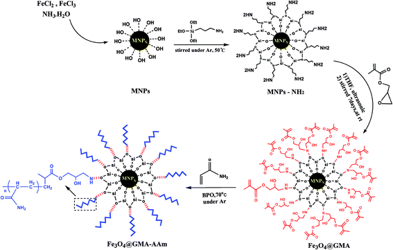 |
| | Scheme 1 Synthetic diagram of the Fe3O4@GMA–AAm nanocomposite. | |
3.1. FT-IR spectroscopy
FT-IR spectroscopy was used to show the structure of the pure Fe3O4 (A), Fe3O4–APTES (B), GMA (C), Fe3O4@GMA (D) and Fe3O4@GMA–AAm (E) magnetic nanocomposites. From the IR spectra presented in Fig. 1, the strong absorption peaks at 585 cm−1 belonged to the stretching vibration mode of Fe–O from the magnetic nanoparticles cores7 and two peaks at 3430 and 1650 cm−1 are attributed to the stretching and bending vibrations of the O–H group respectively.26 The introduction of APTES onto the surface of the Fe3O4-NPs was confirmed by the bands at 1115 and 1060 cm−1 assigned to the Si–O–Si stretching vibrations. The two broad bands at 3446 and 1670 cm−1 can be attributed to the N–H stretching vibration and NH2 bending vibration of free NH2 group respectively.27 Furthermore, hydrogen bonds of terminal NH2 silanols and C–N band also appeared at around 3270 and 1290 cm−1. The presence of the propyl group was confirmed by C–H asymmetric stretching vibration and symmetric stretching vibration that appeared at 2930 and 2841 cm−1.4 Compared to the IR spectrum (C), the IR spectrum (D) of GMA and Fe3O4@GMA, the asymmetrical and symmetrical stretching due to the methyl and methylene groups were observed at 2995 and 2939 cm−1. The stronger absorption band at 1740 cm−1 was attributed to the ester carbonyl stretching of monomer GMA units, evidence that the GMA were successfully grafted onto Fe3O4–APTES nanoparticles. Another band seen at 905 cm−1 was related to the asymmetric stretching of the epoxy group.28 The bands at 1174 and 1289 cm−1 were attributed to the ester C–O symmetric stretching of GMA. However, the identification of a peak attributable to the stretching vibrations of the epoxy groups from GMA with the symmetric stretching and asymmetric stretching vibrations was problematic due to the overlapping of the peaks of Si–O groups.10 The spectrum of the Fe3O4@GMA (D) and Fe3O4@GMA–AAm (E) showed a peak at 2926 cm−1 due to C–H bonds of aliphatic chain stretching vibrations. The broad band at 3433 cm−1 corresponds to the hydrogen bonded O–H and N–H stretching vibration of AAm. The peaks at 1650 and 1732 cm−1 should be assigned to the stretching vibration of the amide and ester C![[double bond, length as m-dash]](https://www.rsc.org/images/entities/char_e001.gif) O respectively from both AAm and GMA. The absorption band at 1400 cm−1 is due to the bending vibration of CH2 and CH3 groups.5
O respectively from both AAm and GMA. The absorption band at 1400 cm−1 is due to the bending vibration of CH2 and CH3 groups.5
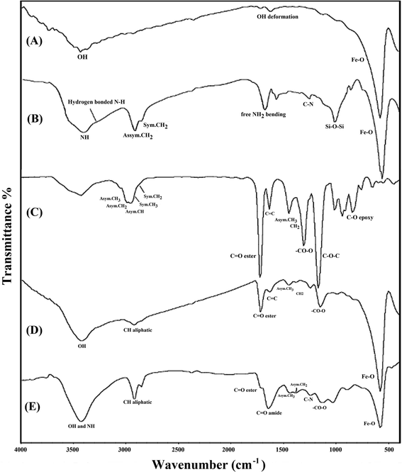 |
| | Fig. 1 FT-IR spectra of the pure Fe3O4 (A), Fe3O4–APTES (B), GMA (C), Fe3O4@GMA (D) and Fe3O4@GMA–AAm nanocomposites (E). | |
3.2. Particle size and morphology studies
The morphology of the magnetic nanocomposite (Fe3O4@GMA–AAm) was characterized by TEM, SEM and AFM techniques. The transmission electron microscope images are shown in Fig. 2. In this image two different areas can been seen, the dark areas may be represented magnetic monomer (Fe3O4) while the bright ones are indications of amorphous polymers formed around the primary particles, so the core–shell structure has been clearly seen and can be taken as evidence of the successful synthesis of Fe3O4@GMA–AAm. The particle size deduced from the TEM images was about 70–150 nm.
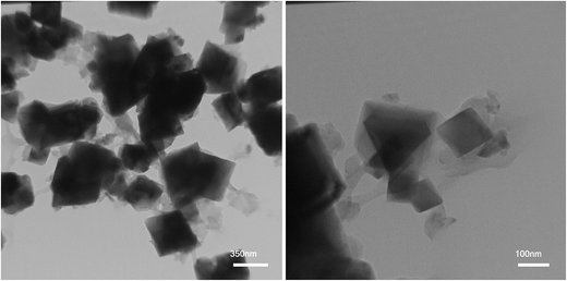 |
| | Fig. 2 TEM images of synthesized nanocomposite in two different area. | |
The surface morphology of the samples was studied by SEM analysis. The SEM images of bare MNPs (A), Fe3O4@GMA (B) and synthesized nanocomposite (C) are given in Fig. 3. As can be seen in Fig. 3A, the MNPs are quasi-spherical in shape with the particle size about 45 nm, while Fig. 3B shows that the Fe3O4@GMA are greater in size than Fe3O4 (about 64 nm) and attached to each other due to modification of the surface of the nanoparticles in two processes using APTES and GMA. The SEM image of nanocomposite in Fig. 3C clearly shows the formation of final product and the growth of the polymer chains on the surface of the nanoparticles. The particle size of the nanocomposites was nearly 88 nm.
 |
| | Fig. 3 SEM images of the bare MNPs (A), Fe3O4@GMA (B) and synthesized nanocomposite (C). | |
The morphology and three-dimensional shape (topography) study of the synthesized nanocomposite was investigated by AFM technique. As shown in Fig. 4A, the topography image clearly shows the polymer chains formed on the surface of the modified nanoparticles. Likewise in Fig. 4B, a phase contrast demonstrates the heterogeneity in the sample that it was due to different structural components in the nanocomposite.
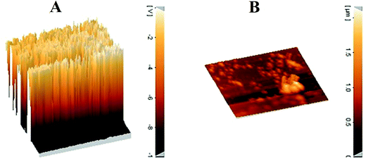 |
| | Fig. 4 AFM images; three-dimensional shape (A) and phase contrast (B) of the Fe3O4@GMA–AAm. | |
3.3. XRD
The crystalline structure of the Fe3O4 nanoparticles before and after surface modification and polymer coating was identified by XRD, and the results were displayed in Fig. 5. The intense diffraction peaks at (2θ = 30.27°, 35.63°, 43.29°, 53.64°, 57. 14°, 62.73° and 74.25°), which corresponded to the (220), (311), (400), (422), (511), (440) and (533), indicated a cubic spinel structure of magnetite (Fig. 5A) which was matched to the standard XRD pattern of magnetite (JCPDS card, file no. 85-1436).29 The same characteristic peaks were also observed for Fe3O4@GMA Fig. 5B and Fe3O4@GMA–AAm Fig. 5C, indicating that during the graft and polymerization process the crystalline phase of the Fe3O4 nanoparticles was largely unchanged. The obvious difference at baseline of the XRD patterns of Fe3O4@GMA and nanocomposite with Fe3O4 nanoparticles showed that the magnetite had been successfully coated by the amorphous structure. The average crystallite size of the materials prepared was obtained from the Debye–Scherrer equation30  where, k (0.89) is the Debye–Scherrer constant, λ (0.15406 nm) is the X-ray wavelength, β is the peak width of half-maximum, θ is the Bragg's angle in degree and D is the average crystalline diameter which was estimated using the strongest peak. In these cases the strongest peak in the three XRD patterns was (3 1 1) at 2θ = 35.63°. The calculated diameters of the Fe3O4, Fe3O4@GMA and Fe3O4@GMA–AAm were seen to be respectively 35.5, 43.75 and 78.84 nm.
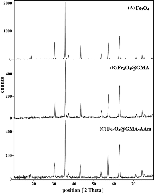 |
| | Fig. 5 XRD patterns of the magnetite (A), Fe3O4@GMA (B), Fe3O4@GMA–AAm (C). | |
3.4. Magnetic measurements
Magnetic measurements of the naked Fe3O4, Fe3O4@GMA and Fe3O4@GMA–AAm were studied with the VSM at room temperature. The hysteresis loops of the three tested nanoparticles are shown in Fig. 6. The magnetic saturation (Ms) values obtained for the Fe3O4, the Fe3O4@GMA and the Fe3O4@GMA–AAm were respectively 80.53, 71.86 and 66.76 emu g−1.27 It can also be observed from this figure that magnetization of pure F3O4 nanoparticles decreased slightly after surface modification with GMA and the coating of the polymer shell on the modified Fe3O4 core. This decrease may be due to the small quenching of the magnetic moment by interplay between the coated layers and the Fe3O4 surface.29 This is another proof of successful coating of the GMA and the polyacrylamide onto the surface of the Fe3O4 nanoparticles. The magnetic property of the Fe3O4@GMA–AAm was still strong enough to be rapidly separated (10 s) from the solution compared to other reported nanocomposites based on Fe3O4 (Table 1) using an external magnetic field (Scheme 2).
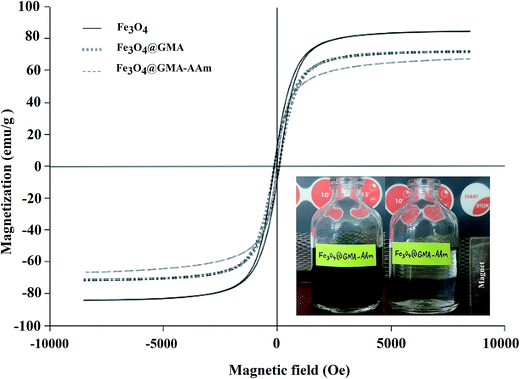 |
| | Fig. 6 Magnetization curves of the naked Fe3O4, Fe3O4@GMA and Fe3O4@GMA–AAm nanocomposite. | |
Table 1 Comparison of saturation magnetization, recovery time and adsorption capacity
| Adsorbents |
Time (s) |
Ms (emu g−1) |
qmax (mg g−1) |
Reference |
| Fe3O4@silica–xanthan gum composites |
180 s |
32.84 |
21.32 |
24 |
| Fe3O4@SiO2 core–shell magnetic nanomaterial |
120 s |
34 |
76.59 |
31 |
| Fe3O4@DAPT core–shell ferromagnetic nanorods |
25 s |
56.1 |
83.3 |
32 |
| Fe3O4–SiO2–poly(1,2-diaminobenzene) core–shell sub-micron particles |
20 s |
60 |
∼65 |
26 |
| DHPCT@Fe3O4 MNPs |
15 s |
24.7 |
52.1 |
33 |
| Fe3O4@GMA–AAm |
10 s |
66.76 |
158.7 |
Present work |
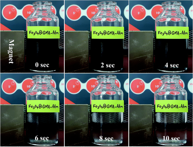 |
| | Scheme 2 Magnetic separation of the Fe3O4@GMA–AAm nanocomposite particles by an external magnet. | |
3.5. TGA analysis
The thermal stability of the Fe3O4@GMA and the Fe3O4@GMA–AAm was investigated by the TGA analysis (Fig. 7). For both of the samples, upon heating from 50 °C to 200 °C, the TGA curves showed a weight loss of about 10% which can be due to the loss of moisture.15 As shown in Fig. 7A, which is related to the Fe3O4@GMA, the weight loss (200–800 °C) is attributed to the decomposition of the coated GMA onto the surface of the Fe3O4 nanoparticles (about 15%). The Fe3O4@GMA–AAm thermogram (Fig. 7B) showed a higher weight loss than the Fe3O4@GMA (about 45%) because of the loss of GMA and polyacrylamide components formed onto the surface of the Fe3O4 nanoparticles.
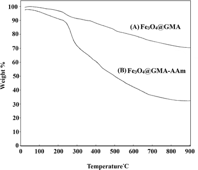 |
| | Fig. 7 TGA curves of the Fe3O4@GMA (A) and the Fe3O4@GMA–AAm (B) nanocomposites. | |
3.6. SEM, EDX and EMA analyses before and after Pb2+ ions adsorption
The SEM micrographs of the Fe3O4@GMA–AAm nanocomposite after adsorption of Pb2+ ions are given in Fig. 8. The SEM images clearly show uniform particles with angular shape. During the adsorption process these particles join together making large particles (∼200 nm), thereby increasing the size of particles after adsorption is apparent with respect to the size of particles before adsorption (88.09 nm).
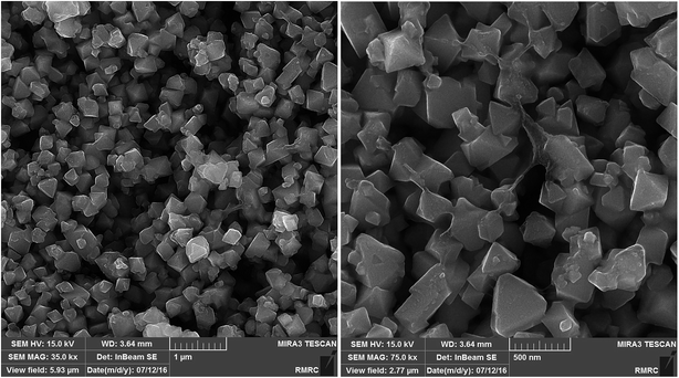 |
| | Fig. 8 SEM micrographs of the Fe3O4@GMA–AAm nanocomposite after Pb2+ ions adsorption. | |
The chemical composition of the Fe3O4@GMA–AAm nanocomposite was analysed by EDX before and after the adsorption of Pb2+ ions onto the nanocomposite surface. The EDX pattern before adsorption clearly showed the presence of Fe, O, N and C (Fig. 9A). After the adsorption of Pb2+ ions, the appearance of lead peaks along with Fe, O, N and C peaks in the EDX spectrum confirms that the Pb2+ ions were taken up onto the surface of prepared adsorbent.
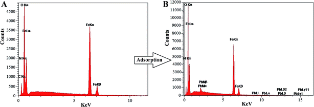 |
| | Fig. 9 EDX pattern of the Fe3O4@GMA–AAm nanocomposite before (A) and after (B) Pb2+ ions adsorption. | |
The elemental mapping analysis by EDX was shown in Fig. 10, that was used for the analysis of the chemical composition and determination of elements. These images indicate the distribution and presence of Fe, O, N, C elements on the surface of the nanocomposite before and after adsorption (Fig. 10A). Also, after adsorption the images of the nanocomposite show the presence of a Pb element, which corroborates the adsorption of the Pb2+ ions by the synthesized magnetic adsorbent (Fig. 10B).
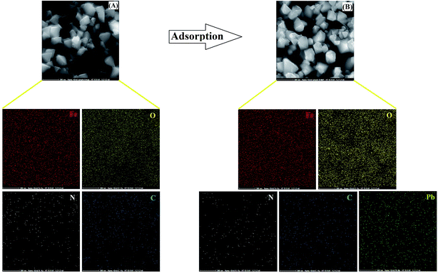 |
| | Fig. 10 EDX elemental mapping of the Fe3O4@GMA–AAm nanocomposite before (A) and after (B) Pb2+ ions adsorption. The images indicate that the atomic symbols correspond to the EDX. | |
3.6.1. Batch adsorption experiments. Adsorption of the Pb2+ ions by the Fe3O4@GMA–AAm nanocomposite was measured from batch adsorption experiments by mixing 10 mg of adsorbent with an aqueous solution containing a predetermined concentration of Pb2+ ions (50 mL). The mixture was shaken at 200 rpm to reach equilibrium. After a specified time, the solid and liquid were separated by external magnet and the concentrations of Pb2+ ions were measured by AAS. To find the optimized pH in adsorption of Pb2+ ions the effect of the pH was studied. The initial pH of the solutions was adjusted in the range of 2.0–7.0 by adding 0.1 N HCl or 0.1 N NaOH solution at 25 °C. The effect of the dosage of adsorbent on the adsorption was also determined with different nanocomposites dosages (0.005–0.03 g/50 mL Pb2+ ions, 10 mg L−1). The Langmuir, Freundlich and Dubinin–Radushkevich (D–R) adsorption isotherms were studied at different temperatures, namely 15, 25, 35 and 45 °C (the adsorbent dosage 0.007 g in 50 mL Pb2+ ions solution) with constant shaking (200 rpm). The effect of contact time between solution and adsorbent was also investigated to analyse the adsorption kinetics at a pH of 6 at room temperature. The kinetics of the adsorption process were carried out by adding 0.007 g of adsorbent into 50 mL of 10 mg L−1 Pb2+ ions solution, at different times at 25 °C. For the kinetic study, pseudo-first-order and pseudo-second-order models were studied.The concentrations of the metal ions in the adsorption solutions were determined by AAS. According to the experimental results obtained, a mechanism which can be proposed for the adsorption of Pb2+ ions on the Fe3O4@GMA–AAm surface was shown in Scheme 3.
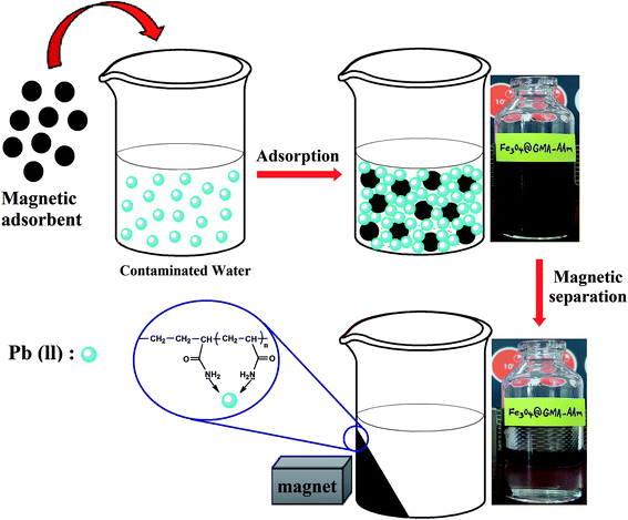 |
| | Scheme 3 Schematic illustration of adsorption mechanism of the Fe3O4@GMA–AAm nanocomposite. | |
The equilibrium adsorption capacity (qe) (mg g−1) for Pb2+ ions was calculated according to the following equation:
| |
 | (1) |
where
C0 and
Ce (mg L
−1) are respectively the initial and equilibrium Pb
2+ ions aqueous concentrations.
V is the volume (mL) of Pb
2+ ions aqueous solution;
m is the mass (mg) of adsorbents used in the experiment. The removal percentage of metal ions was calculated using the following equation:
| |
 | (2) |
3.7. Adsorption study of the Fe3O4@GMA–AAm adsorbent
3.7.1. Effect of pH value. The pH value of the media is one of the most important factors in the adsorption of metal ions. It is well known that Pb2+ ions are present in several forms in media depending on the pH solution: these are Pb2+, Pb(OH)+, Pb(OH)2, and Pb(OH)3.34 The effect of pH on the adsorption of Pb2+ ions with Fe3O4@GMA–AAm nanocomposite was investigated in pH ranges between 2.0 and 7.0 at 25 °C with an initial Pb2+ ions concentration of 10 mg L−1. The results showed that the adsorption of Pb2+ ions in solution completely depends on pH, in fact in acidic pH the H+ ions competes with the Pb2+ ions to reach functional groups of synthesized composite. Thus the adsorption of Pb2+ ions in acidic media is low. Therefore the efficient removal of the Pb2+ ions appeared at pH 6.0 and reached a constant state up to pH 7.0. It can be said that at pH around 6.0 Pb2+ ions are the main element substance in the solution. When the pH is above 6.0 the solubility of Pb(OH)2 is very low and the precipitation of lead ions prevails. The Fe3O4@GMA–AAm displayed a maximum Pb2+ ions removal efficiency of 99% at pH 6.0. Therefore pH 6 appeared to be the optimal condition and was chosen as the optimal pH for the following experiments. The effect of pH on lead adsorption is shown in Fig. 11A.
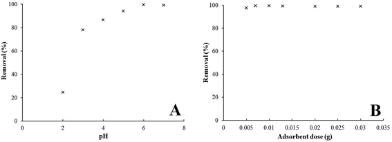 |
| | Fig. 11 Effect of pH (A) and adsorbent dosage (B) on Pb2+ ions adsorption by Fe3O4@GMA–AAm (initial Pb2+ ions concentration: 10 mg L−1, agitation rate: 200 rpm, contact time: 2 min, T = 298 K). | |
3.7.2. Effect of adsorbent dosage. To determine the optimal adsorbent dose for the Pb2+ ions solution (50 mL) at an initial concentration of 10 mg L−1, various adsorbent dosages (0.005, 0.007, 0.01, 0.013, 0.02, 0.025 and 0.03 g) of synthesized Fe3O4@GMA–AAm were added. The results of the experiments are presented in Fig. 11B. It can be seen that the efficient removal of metal ions increased from 97% to 99.5% with an increase in the dosage of adsorbent from 0.005 g to 0.01 g. Increasing the dose of adsorbent enabled the number of available adsorption sites to increase, so the removal percentage of Pb2+ ions increased. After that, as the dosage continued to increase, the adsorption levels reached a steady state value or possibly even started to decrease slightly. This result can be explained by the increased likelihood of contact between these small particles due to increased adsorbent dose and also to the shaking process in a horizontal shaker, leading to aggregation, thus as a result the total surface area and active sites of adsorbent decreased.35 The optimal dosage of the nanocomposite for the adsorption of Pb2+ ions was therefore found to be about 0.007 g/50 mL.
3.7.3. Effect of adsorption time. The contact time between the metal ions and adsorbent plays an important role in the adsorption process and revealed the minimum time required for the removal of the maximum percentage of pollutants from the media. Fig. 12A shows the contact time vs. the removal percentage curves. It can be observed that the uptake of Pb2+ ions was very rapid and a large amount of this toxic ion was removed within a few minutes (2 min). The fast adsorption process may be the result of the fast kinetics of active sites on the surface of the synthesized composite in the adsorption of Pb2+ ions along with a large number of accessible active adsorption sites on the uncovered absorbent surface.36 After this time there was no significant change in terms of the amount of adsorption due to the saturation of the active sites on the absorbent surface. Therefore the equilibrium time for the synthesized nanocomposite was found to be about 2 min.
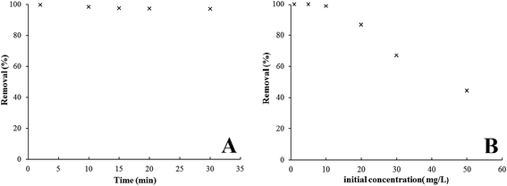 |
| | Fig. 12 Effect of adsorption time (A) and initial concentration (B) on Pb2+ ions adsorption by the Fe3O4@GMA–AAm nanocomposite (adsorbent dose: 0.007 g/50 mL Pb2+ ions, agitation rate: 200 rpm, pH 6, T: 298 K). | |
3.7.4. Effect of initial concentration. Solutions with different initial concentrations of Pb2+ ions (1, 5, 10, 20, 30, 50 mg L−1) were used to study the effect of concentration variation on the removal of metal ions by 0.007 g L−1 adsorbent at pH 6 and temperature 298 K. It can be seen from Fig. 12B that the removal yield decreased from 99 to 44% as the initial Pb2+ ions concentration increased. Therefore at a higher initial concentration of Pb2+ ions the adsorption was decreased due to the active sites of the adsorbent being rapidly occupied by metal ions and the number of accessible adsorption sites was reduced.32
3.7.5. Effect of solution temperature. Temperature plays an important role in the adsorption process as it provides valuable information on three basic thermodynamic parameters; the standard Gibbs free energy, enthalpy and entropy changes. The changes in these parameters were used to characterize the adsorption thermodynamics. In this study the Pb2+ ions adsorption experiment was performed with varying temperatures from 10 °C to 45 °C using 0.007 g of adsorbent and pH 6. Fig. 13A shows the removal percentage of Pb2+ ions which were adsorbed onto the nanoadsorbent at different temperatures. The results showed that adsorption increased slightly from 94.3 to 99.5% when the temperature increased from 10 °C to 25 °C. This result showed that the adsorption of the lead ions was an endothermic process. The increase in the adsorption with the increase in temperature may be due to the increase in the mobility of the ions, which can be probably increase the number of ions for interaction with active sites.37 Raising the temperature to 25 °C revealed no obvious variation for Pb2+ ions because in the whole range of temperature investigated the adsorption rate is about 99.5%.
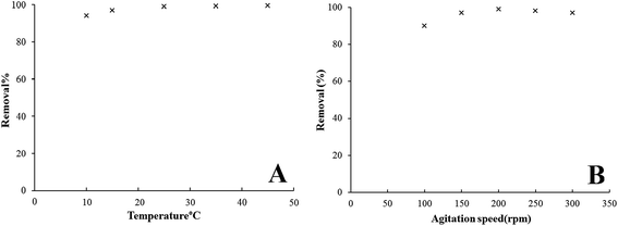 |
| | Fig. 13 Effect of solution temperature (A) and agitation rate (B) on Pb2+ ions adsorption by the Fe3O4@GMA–AAm nanocomposite (initial Pb2+ ions concentration: 10 mg L−1, contact time: 2 min, adsorbent dose: 0.007 g/50 mL Pb2+ ions, pH 6). | |
3.7.6. Effect of agitation rate. Agitation speed is an effective parameter in the adsorption performance and influences the distribution of the solute in the solution. The effect of agitation rate on removal percentage efficiency for Pb2+ ions was studied by varying the rate of agitation from 100 to 300 rpm, while the other conditions were held constant. As shown in Fig. 13B, when the agitation rate increased to 200 rpm, the adsorption capacity also increased. This was due to the additional turbulence that raised the diffusion of the adsorbate ions into the internal surface of adsorbent. This also decreased the boundary layer thickness around the adsorbent particles.38 Further increase in the agitation rate to 250 and 300 rpm reduced the adsorption capacity, because the extreme turbulence caused a decrease in the interplay time between the adsorbent and adsorbate ions. An agitation speed of 200 rpm was therefore selected as optimal.
3.7.7. Effects of adsorption kinetics. To investigate adsorption kinetics and describe the rate of the adsorption mechanisms of the Pb2+ ions onto the magnetic nanocomposite, two kinetic models were used to fit the experimental data. These models are the Lagergren pseudo-first-order and the Ho pseudo-second-order equations.39 The Lagergren kinetic model describes the rate of adsorption proportional to the number of unoccupied sites by the solutes and is expressed in the following linear equation:| |
 | (3) |
where qe and qt are the numbers of Pb2+ ions adsorbed (mg g−1) at equilibrium and at time t (min) respectively. k1 (min−1) is the pseudo-first-order adsorption kinetic constant. k1 and qe can be obtained from the slope and intercept of log(qe − qt) versus t (Fig. 14A). The Ho kinetic model based on adsorption equilibrium capacity assumes that the rate of possession for adsorption sites is proportional to the square of the number of unoccupied sites. The adsorption rate is dependent on the concentration of the activated sites on the surface of adsorbent. This model is expressed by the following equation:| |
 | (4) |
where k2 (g mg−1 min−1) is the pseudo-second-order adsorption kinetic parameter and both k2 and qe can be obtained from the intercept and slope of the graph of (t/qt) versus t (Fig. 14B).36 The experimental data of two kinetic models are calculated and shown in Table 2. The rate constants, correlation coefficients (R) and calculated qe for the two kinetic models of nanocomposite showed that the fit of the pseudo-first-order model with the experimental was poor according to the low correlation coefficients. Also the calculated equilibrium adsorption capacities (qe,cal) digressed too much from the measured values (qe,exp). These results indicate that the applicability of the pseudo-second-order kinetic model with excellent correlation coefficients and good agreement between calculated qe and measured qe, is more appropriate to describe the adsorption process of Pb2+ ions on the nanocomposite. Therefore it can be concluded that the adsorption of Pb2+ ions onto Fe3O4@GMA–AAm perfectly obeyed the pseudo-second-order kinetic model and suggests chemical adsorption as the rate-controlling step of the adsorption mechanism.30
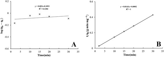 |
| | Fig. 14 Kinetic models of Pb2+ ions adsorption onto the nanocomposite using pseudo-first-order (A), and pseudo-second-order model (B). | |
Table 2 Kinetic parameters for Pb2+ ions adsorption using Fe3O4@GMA–AAm
| Kinetic models and parameters |
Pb2+ ions |
| Pseudo-first-order model |
| qe,exp (mg g−1) |
70.71 |
| qe,cal (mg g−1) |
0.784 |
| k1 (min−1) |
−0.0046 |
| R2 |
0.1284 |
| NSD (%) |
49.9 |
![[thin space (1/6-em)]](https://www.rsc.org/images/entities/char_2009.gif) |
| Pseudo-second-order model |
| qe,exp (mg g−1) |
70.71 |
| qe,cal (mg g−1) |
69.93 |
| k2 (g mg−1 min−1) |
1.02 |
| R2 |
1 |
| NSD (%) |
0.551 |
3.7.8. Validity of the kinetic model. In addition, the values of normalized standard deviation (NSD) (%) were also calculated to confirm the fitness of the kinetic models to the experimental data,40 which is defined as:| |
 | (5) |
where N is the number of measurements, qe,exp and qe,cal (mg g−1) are the experimental and calculated equilibrium adsorption capacity values respectively. The parameters and measured NSD (%) values for the two kinetic models are shown in Table 2. The NSD (%) values obtained for the pseudo-first-order model were higher than the NSD (%) values obtained for the pseudo-second-order model. Therefore the pseudo-second-order model was fitted with higher R2 to illustrate the adsorption kinetics of the Pb2+ ions because a smaller NSD (%) value indicates a better fitting kinetic model.
3.7.9. Adsorption isotherms. To understand the adsorption mechanism of Pb2+ ions on the adsorbent, the adsorption data were analysed by adsorption isothermal models. The adsorption isotherm is a functional parameter and one of the most useful for understanding the mechanism of adsorption that shows how the adsorbate molecules are distributed between the liquid phase and solid phase. These indicate the relationship between the amount of solute adsorbed per unit weight of the adsorbent and the concentration of an adsorbate in solution at a given temperature under equilibrium conditions. Among the many models proposed to explain adsorption equilibrium, the Langmuir, Freundlich and Dubinin–Radushkevich (D–R) adsorption isotherm models were used in this study to describe the equilibrium between adsorbed Pb2+ ions on Fe3O4@GMA–AAm (qe) and Pb2+ ions in solution (Ce) at constant temperature.The Langmuir model has been successfully applied in many adsorption processes and states that adsorption takes place at particular homogeneous sites into the adsorbent surface by monolayers with no transmigration of adsorbed ions on the plane of the surface. The Langmuir isotherm is described by the following equation:17
| |
 | (6) |
It can also be determined by transforming eqn (6) into linear form:
| |
 | (7) |
where
qe represents the number of Pb
2+ ions adsorbed onto the absorbent surface in equilibrium state (mg g
−1);
Ce is the equilibrium Pb
2+ ions concentration (mg L
−1);
qm denotes the maximum adsorption capacity corresponding to complete monolayer coverage and
KL is the Langmuir adsorption equilibrium constant (L mg
−1). When
Ce/
qe is plotted against
Ce, a straight line is obtained, so
qm and
KL values were defined respectively from the slope and the intercept of the linear plots. The results are presented in
Fig. 15A.
 |
| | Fig. 15 Langmuir (A), Freundlich (B) and D–R (C) adsorption isotherms for Pb2+ ions adsorption onto the magnetic adsorbent. | |
The amount of RL factor indicates that the type of isotherm is irreversible (RL = 0), favourable (0 < RL < 1), linear (RL = 1) or unfavourable (RL > 1). The RL, is defined by the following equation:41
| |
 | (8) |
where
C0 (mg L
−1) is the initial concentration of Pb
2+ ions. The
RL values in this study showed favourable adsorption between Pb
2+ ions and adsorbent.
The Freundlich isotherm model is an experimental equation valid for multilayer adsorption on a heterogeneous adsorbent surface with a non-uniform distribution of adsorption heat. It is used to evaluation the adsorption intensity of the adsorbent to the adsorbate and it was assumed that at the first strong and quick adsorption occurs at binding sites, which depends on the ions concentration in the solution. The binding strength was decreased with the increasing of occupied site.37 The Freundlich isotherm model is given by the following equation:
| |
 | (9) |
The linear form can be expressed as follows:
| |
 | (10) |
where
KF is the Freundlich constant indicating adsorption capacity;
n is an experimental parameter related to the intensity of adsorption. The amount of heterogeneity of the adsorbent may change the value of
n and for a favorable adsorption process the value of
n should be in the range 1–10. The
KF and
n can be calculated from the intercept and slope of linear plot of ln
![[thin space (1/6-em)]](https://www.rsc.org/images/entities/char_2009.gif) qe vs.
qe vs. ln
![[thin space (1/6-em)]](https://www.rsc.org/images/entities/char_2009.gif) Ce
Ce respectively (
Fig. 15B).
The Dubinin–Radushkevich isotherm is universally applied to represent the adsorption mechanism between physical and chemical adsorption onto a heterogeneous surface with a Gaussian energy distribution.42 This adsorption model is represented by the following equation:
The linear form of the D–R isotherm equation is:
| | |
ln(qe) = ln(qexp) − βε2
| (12) |
where
ε is the activity coefficient related to mean adsorption energy (mol
2 J
−2);
qe is the amount of adsorbate in the adsorbent at equilibrium (mg g
−1);
qmax is the maximum adsorption capacity of Pb
2+ ions on the adsorbent corresponding to D–R monolayer coverage (mg g
−1). If ln
![[thin space (1/6-em)]](https://www.rsc.org/images/entities/char_2009.gif) qe
qe is plotted against
ε2,
β and
qmax will be obtained from the slope and intercept respectively (
Fig. 15C). The parameter
ε is the Polanyi potential, which can be calculated as the following relation:
| |
 | (13) |
where
R (8.314 J mol
−1 K
−1) is the gas constant and
T (K) is the absolute temperature. The
β gives the mean free energy
E (kJ mol
−1) of adsorption per molecule of adsorbate when it is transferred to the surface of the absorbent from infinity in the solution and can be calculated using the following relationship:
| |
 | (14) |
The magnitude of this parameter is useful for information about the type of sorption process such as chemical ions exchange or physical sorption. When it lies between 8 and 16 (kJ mol−1), the adsorption occurs chemically. However, the reaction proceeds physically as it smaller than 8 kJ mol−1.43 It can be seen that the E value in this study is between 8 and 16 (kJ mol−1), indicating that the adsorption of Pb2+ ions may be interpreted as chemical ion exchange adsorption.
The Langmuir, Freundlich and D–R parameters for the adsorption of Pb2+ ions onto the magnetic adsorbent were summarized in Table 3. It was obvious that the Langmuir model fitted the experimental data better than the other models based on the R2 values in Table 3.
Table 3 Parameters of isotherm models for adsorption of Pb2+ ions by adsorbent
| Isotherms and linear equations |
Parameters |
Pb2+ ions |
Langmuir  |
qm (mg g−1) |
158.73 |
| KL (L mg−1) |
3.15 |
| RL |
0.03 |
| R2 |
0.9984 |
Freundlich  |
KF (mg g−1) |
90.07 |
| N |
4.06 |
| R2 |
0.9264 |
| Dubinin–Radushkevich ln(qe) = ln(qexp) − βε2 |
qmax (mg g−1) |
124.83 |
| E (kJ mol−1) |
8.45 |
| β (mol2 kJ−2) |
7 × 10⁻⁹ |
| R2 |
0.9704 |
3.8. Effect of coexisting ions
Various toxic metal ions generally present in wastewater and the sample matrix may interfere in the removal efficiency of Pb2+ ions in media. The effects of coexisting cationic ions on the Pb2+ ions adsorption were studied and investigated in 50 mL solutions containing 10 mg L−1 of metal ions such as Ag+, Fe2+, Cu2+, Zn2+, Cd2+ ions. As seen in Fig. 16, the decreased number of Pb2+ ions in the presence of coexisting ions was lower than the decreased amount of Pb2+ ions in the absence of coexisting ions in solution. However, the results indicated that the adsorbent illustrated good selectivity for Pb2+ ions in the presence of coexisting ions. In general the competitive adsorption ability changes from one metal ion to another, which may be related to factors such as molecular mass, ion charges, hydrated ionic radius and hydration energy of the ionic metal.35 Apparently the coexisting cations compete with Pb2+ ions for the active sites on the magnetic adsorbent. Therefore the number of active sites on the surface of the adsorbent was decreased for the adsorption of Pb2+ ions in solution.
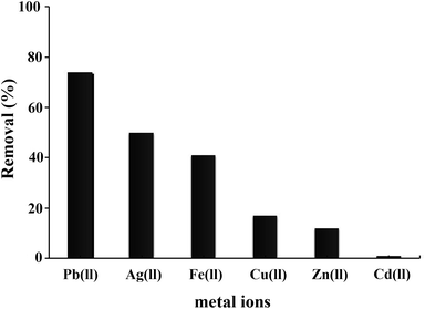 |
| | Fig. 16 Effect of coexisting cationic ions on the Pb2+ ions adsorption onto the magnetic adsorbent. | |
3.9. Thermodynamic studies
The effect of various temperatures on the adsorption process was investigated to assess the spontaneity of the adsorption process. This provided valuable information about three thermodynamic parameters, Gibbs' free energy (ΔG°), enthalpy (ΔH°) and entropy (ΔS°) that change during the adsorption. In order to obtain the thermodynamic of the adsorption process, 0.007 g of adsorbent was added into 50 mL of Pb2+ ion solution with an initial concentration of 10 mg L−1 at different temperatures (283, 288, 298, 308, and 318 K). The amounts of ΔG° can be determined by using the following equations.32| |
ΔG° = −RT![[thin space (1/6-em)]](https://www.rsc.org/images/entities/char_2009.gif) ln ln![[thin space (1/6-em)]](https://www.rsc.org/images/entities/char_2009.gif) Keq Keq
| (15) |
| |
 | (16) |
where R is the ideal gas constant (8.314 J mol−1 K−1), T is the temperature (K) and Keq is the adsorption equilibrium constant. Keq can be calculated by eqn (16) and the enthalpy (ΔH°) and the entropy (ΔS°) can be determined from the van't Hoff equation44 that shows the dependence of the equilibrium constant on the adsorption process on temperature as follows:
The van't Hoff equation (eqn (18)) is obtained by combining eqn (15) and (17) as follows:
| |
 | (18) |
The values of ΔH° and ΔS° were calculated from the slope and intercept of the van't Hoff plots of ln(Keq) vs. 1/T respectively, as presented in Fig. 17. The calculated thermodynamic parameters for the sorption of Pb2+ ions onto the Fe3O4@GMA–AAm surface are reported in Table 4. As can be seen, the ΔG° at given temperatures was a negative value, confirming that the adsorption of Pb2+ ions onto the adsorbent was spontaneous and thermodynamically favourable adsorption had occurred. The positive value of ΔH° suggests that the interaction between Pb2+ ions and nanoadsorbent is endothermic in nature, while the positive value of ΔS° may be attributed to the increase of randomness in the solid/liquid interface during the adsorption process.45 All the thermodynamic data indicated that the adsorption of Pb2+ ions onto Fe3O4@GMA–AAm is favourable and can be used as an efficient adsorbent to remove Pb2+ ions from aqueous solution.
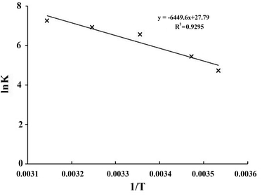 |
| | Fig. 17 Determination of thermodynamic parameters for the adsorption of Pb2+ ions onto the Fe3O4@GMA–AAm nanocomposite. | |
Table 4 Thermodynamic parameters of Pb2+ ions adsorption at different temperatures using nanocomposite
| T (K) |
Keq (mL g−1) |
ΔG° (kJ mol−1) |
ΔH° (kJ mol−1) |
ΔS° (J mol−1 K−1) |
| 283 |
111.9 |
−11.09 |
+50.786 |
+213.59 |
| 288 |
230.9 |
−13.03 |
|
|
| 298 |
707.1 |
−16.25 |
|
|
| 308 |
1013.14 |
−17.72 |
|
|
| 318 |
1421.4 |
−19.19 |
|
|
4. Conclusion
The Fe3O4@GMA–AAm magnetic nanocomposite was successfully synthesized as a novel adsorbent for the efficient and fast removal of Pb2+ ions from aqueous media. The TEM image showed the core–shell structure and the growth of the polymer chains on the surface of the nanoparticles could also be seen in the SEM and AFM images. The equilibrium time of Pb2+ ions adsorption was very short and obtained within 2 min. The kinetic models were applied to the experimental data. The adsorption was found to follow the pseudo-second-order model, and chemical adsorption was the rate controlling step of the adsorption. The isotherm analysis indicated that the adsorption of Pb2+ ions fitted the Langmuir equation well. The thermodynamic parameters showed that the adsorption process was spontaneous and endothermic in nature. As a result, our synthesized Fe3O4@GMA–AAm nanocomposite with suitable core–shell structure, easy separation method, high adsorption capacity and rapid adsorption rate (158.73 mg g−1 and 2 min) may be a good magnetic adsorbent for the removal of Pb2+ ions from aqueous solutions, compared to some other reported nanocomposites based on Fe3O4 (Table 1).
References
- Y. Shen, J. Tang, Z. Nie, Y. Wang, Y. Ren and L. Zuo, Sep. Purif. Technol., 2009, 68, 312–319 CrossRef CAS.
- R. Hasanzadeh, P. Najafi Moghadam and N. Samadi, Polym. Adv. Technol., 2013, 24, 34–41 CrossRef CAS.
- M. H. Mashhadizadeh and Z. Karami, J. Hazard. Mater., 2011, 190, 1023–1029 CrossRef CAS PubMed.
- P. Castaldi, M. Silvetti, G. Garau, D. Demurtas and S. Deiana, J. Hazard. Mater., 2015, 283, 140–147 CrossRef CAS PubMed.
- F. Ge, M.-M. Li, H. Ye and B.-X. Zhao, J. Hazard. Mater., 2012, 211, 366–372 CrossRef PubMed.
- N. Samadi, R. Hasanzadeh and M. Rasad, J. Appl. Polym. Sci., 2015, 132, 41642 Search PubMed.
- S. Luo, T. Lu, L. Peng, J. Shao, Q. Zeng and J.-D. Gu, J. Mater. Chem. A, 2014, 2, 15463–15472 CAS.
- Ş. Taşar, F. Kaya and A. Özer, J. Environ. Chem. Eng., 2014, 2, 1018–1026 CrossRef.
- A. Z. M. Badruddoza, Z. B. Z. Shawon, W. J. D. Tay, K. Hidajat and M. S. Uddin, Carbohydr. Polym., 2013, 91, 322–332 CrossRef CAS PubMed.
- M. Hua, S. Zhang, B. Pan, W. Zhang, L. Lv and Q. Zhang, J. Hazard. Mater., 2012, 211, 317–331 CrossRef PubMed.
- Z. Li, Y. Kong and Y. Ge, Chem. Eng. J., 2015, 270, 229–234 CrossRef CAS.
- M. K. Krušić, N. Milosavljević, A. Debeljković, Ö. Üzüm and E. Karadağ, Water, Air, Soil Pollut., 2012, 223, 4355–4368 CrossRef.
- N. N. Nassar, J. Hazard. Mater., 2010, 184, 538–546 CrossRef CAS PubMed.
- S. Ghorai, A. Sinhamahpatra, A. Sarkar, A. B. Panda and S. Pal, Bioresour. Technol., 2012, 119, 181–190 CrossRef CAS PubMed.
- M. Ozmen, K. Can, G. Arslan, A. Tor, Y. Cengeloglu and M. Ersoz, Desalination, 2010, 254, 162–169 CrossRef CAS.
- T. Wang, L. Zhang, C. Li, W. Yang, T. Song, C. Tang, Y. Meng, S. Dai, H. Wang and L. Chai, Environ. Sci. Technol., 2015, 49, 5654–5662 CrossRef CAS PubMed.
- Y.-M. Hao, C. Man and Z.-B. Hu, J. Hazard. Mater., 2010, 184, 392–399 CrossRef CAS PubMed.
- L. Feng, M. Cao, X. Ma, Y. Zhu and C. Hu, J. Hazard. Mater., 2012, 217, 439–446 CrossRef PubMed.
- D. Horák, M. Trchová, M. J. Beneš, M. Veverka and E. Pollert, Polymer, 2010, 51, 3116–3122 CrossRef.
- H. V. Tran, L. Dai Tran and T. N. Nguyen, Mater. Sci. Eng. C, 2010, 30, 304–310 CrossRef CAS.
- C. Zhang, Z. Mo, P. Zhang, C. Feng and R. Guo, Mater. Lett., 2013, 106, 107–110 CrossRef CAS.
- S.-H. Huang and D.-H. Chen, J. Hazard. Mater., 2009, 163, 174–179 CrossRef CAS PubMed.
- Y.-G. Zhao, H.-Y. Shen, S.-D. Pan and M.-Q. Hu, J. Hazard. Mater., 2010, 182, 295–302 CrossRef CAS PubMed.
- X. Peng, F. Xu, W. Zhang, J. Wang, C. Zeng, M. Niu and E. Chmielewská, Colloids Surf., A, 2014, 443, 27–36 CrossRef CAS.
- D. Maity and D. Agrawal, J. Magn. Magn. Mater., 2007, 308, 46–55 CrossRef CAS.
- F. Zhang, J. Lan, Z. Zhao, Y. Yang, R. Tan and W. Song, J. Colloid Interface Sci., 2012, 387, 205–212 CrossRef CAS PubMed.
- B. Saif, C. Wang, D. Chuan and S. Shuang, J. Biomater. Nanobiotechnol., 2015, 6, 267 CrossRef.
- L. Lei, X. Liu, Y. Li, Y. Cui, Y. Yang and G. Qin, Mater. Chem. Phys., 2011, 125, 866–871 CrossRef CAS.
- J. Liu, W. Wang, H. Liu, Y. Zhou, H. Zhang and X. Zhou, RSC Adv., 2014, 4, 25983–25992 RSC.
- X. Guan, J. Chang, Y. Chen and H. Fan, RSC Adv., 2015, 5, 50126–50136 RSC.
- J. Wang, S. Zheng, Y. Shao, J. Liu, Z. Xu and D. Zhu, J. Colloid Interface Sci., 2010, 349, 293–299 CrossRef CAS PubMed.
- S. Venkateswarlu and M. Yoon, ACS Appl. Mater. Interfaces, 2015, 7, 25362–25372 CAS.
- S. Venkateswarlu and M. Yoon, Dalton Trans., 2015, 44, 18427–18437 RSC.
- V. K. Gupta, S. Agarwal and T. A. Saleh, J. Hazard. Mater., 2011, 185, 17–23 CrossRef CAS PubMed.
- L. Xiong, C. Chen, Q. Chen and J. Ni, J. Hazard. Mater., 2011, 189, 741–748 CrossRef CAS PubMed.
- N. Sharma and A. Tiwari, Desalin. Water Treat., 2016, 57, 3642–3653 CrossRef CAS.
- R. M. Ali, H. A. Hamad, M. M. Hussein and G. F. Malash, Ecol. Eng., 2016, 91, 317–332 CrossRef.
- H. Chong, P. Chia and M. Ahmad, Bioresour. Technol., 2013, 130, 181–186 CrossRef CAS PubMed.
- Y. Lin, H. Chen, K. Lin, B. Chen and C. Chiou, J. Environ. Sci., 2011, 23, 44–50 CrossRef CAS.
- B. Cheng, Y. Le, W. Cai and J. Yu, J. Hazard. Mater., 2011, 185, 889–897 CrossRef CAS PubMed.
- K. Hall, L. Eagleton, A. Acrivos and T. Vermeulen, Ind. Eng. Chem. Fundam., 1966, 5, 212–223 CAS.
- A. Dada, A. Olalekan, A. Olatunya and O. Dada, J. Appl. Chem., 2012, 3, 38–45 Search PubMed.
- H. Zheng, D. Liu, Y. Zheng, S. Liang and Z. Liu, J. Hazard. Mater., 2009, 167, 141–147 CrossRef CAS PubMed.
- B. Tanhaei, A. Ayati, M. Lahtinen and M. Sillanpää, Chem. Eng. J., 2015, 259, 1–10 CrossRef CAS.
- D. Ding, Y. Zhao, S. Yang, W. Shi, Z. Zhang, Z. Lei and Y. Yang, Water Res., 2013, 47, 2563–2571 CrossRef CAS PubMed.
|
| This journal is © The Royal Society of Chemistry 2017 |
Click here to see how this site uses Cookies. View our privacy policy here.  Open Access Article
![[thin space (1/6-em)]](https://www.rsc.org/images/entities/char_2009.gif) :
:![[thin space (1/6-em)]](https://www.rsc.org/images/entities/char_2009.gif) 2. Then the hydroxyl groups on the surface of Fe3O4 were allowed to react with APTES for the preparation of MNPs–NH2. After that the MNPs–NH2 was allowed to react with the epoxy group of GMA to form Fe3O4–GMA. The products were characterized by various techniques as mentioned described below. The overall synthetic procedure was presented in Scheme 1.
2. Then the hydroxyl groups on the surface of Fe3O4 were allowed to react with APTES for the preparation of MNPs–NH2. After that the MNPs–NH2 was allowed to react with the epoxy group of GMA to form Fe3O4–GMA. The products were characterized by various techniques as mentioned described below. The overall synthetic procedure was presented in Scheme 1.
![[double bond, length as m-dash]](https://www.rsc.org/images/entities/char_e001.gif) O respectively from both AAm and GMA. The absorption band at 1400 cm−1 is due to the bending vibration of CH2 and CH3 groups.5
O respectively from both AAm and GMA. The absorption band at 1400 cm−1 is due to the bending vibration of CH2 and CH3 groups.5

 where, k (0.89) is the Debye–Scherrer constant, λ (0.15406 nm) is the X-ray wavelength, β is the peak width of half-maximum, θ is the Bragg's angle in degree and D is the average crystalline diameter which was estimated using the strongest peak. In these cases the strongest peak in the three XRD patterns was (3 1 1) at 2θ = 35.63°. The calculated diameters of the Fe3O4, Fe3O4@GMA and Fe3O4@GMA–AAm were seen to be respectively 35.5, 43.75 and 78.84 nm.


![[thin space (1/6-em)]](https://www.rsc.org/images/entities/char_2009.gif)


![[thin space (1/6-em)]](https://www.rsc.org/images/entities/char_2009.gif) qe vs. ln
qe vs. ln![[thin space (1/6-em)]](https://www.rsc.org/images/entities/char_2009.gif) Ce respectively (Fig. 15B).
Ce respectively (Fig. 15B).
![[thin space (1/6-em)]](https://www.rsc.org/images/entities/char_2009.gif) qe is plotted against ε2, β and qmax will be obtained from the slope and intercept respectively (Fig. 15C). The parameter ε is the Polanyi potential, which can be calculated as the following relation:
qe is plotted against ε2, β and qmax will be obtained from the slope and intercept respectively (Fig. 15C). The parameter ε is the Polanyi potential, which can be calculated as the following relation:

![[thin space (1/6-em)]](https://www.rsc.org/images/entities/char_2009.gif) ln
ln![[thin space (1/6-em)]](https://www.rsc.org/images/entities/char_2009.gif) Keq
Keq


