 Open Access Article
Low-temperature fabrication of Bi25FeO40/rGO nanocomposites with efficient photocatalytic performance under visible light irradiation
Xingfu Wangab,
Weiwei Maoab,
Qi Wanga,
Yiyi Zhua,
Yonggang Mina,
Jian Zhanga,
Tao Yanga,
Jianping Yangb,
Xing'ao Li *ab and
Wei Huang*ac
aKey Laboratory for Organic Electronics & Information Displays (KLOEID), Institute of Advanced Materials (IAM), School of Materials Science and Engineering (SMSE), Nanjing University of Posts and Telecommunications (NUPT), Nanjing 210023, PR China. E-mail: lxahbmy@126.com; iamwhuang@njupt.edu.cn
bSchool of Science, Advanced Energy Technology Center, Nanjing University of Posts and Telecommunications (NUPT), Nanjing 210023, PR China
cKey Laboratory of Flexible Electronics (KLOFE), Institute of Advanced Materials (IAM), National Synergistic Innovation Center for Advanced Materials (SICAM), Nanjing Tech University (NanjingTech), 30 South Puzhu Road, Nanjing 211816, China
First published on 6th February 2017
Abstract
Bismuth ferrite/reduced graphene oxide (Bi25FeO40/rGO) nanocomposites have been synthesized by a hydrothermal method, followed by a simple room temperature liquid phase process. Interestingly, X-ray diffraction and scanning electron microscopy analyses indicated that the presence of rGO triggered the transformation of perovskite phase BiFeO3 to sillenite phase Bi25FeO40 at room temperature, while the spindle-like morphology was maintained. Under visible light irradiation, the obtained Bi25FeO40/rGO nanocomposites exhibit high photocatalytic performance for the degradation of methyl orange (MO), suggesting potential applications in photocatalytic and related areas. Furthermore, the function of rGO for the enhancement of photocatalytic activity and the probable mechanism were also discussed on the basis of the results.
1. Introduction
Bismuth ferrites, a large family of transition-metal oxides, have recently attracted great interest due to their fascinating fundamental physics and extensive technical applications.1–3 BiFeO3 is known to be a typical perovskite-type bismuth ferrite with simultaneous ferroelectric and ferromagnetic ordering at room temperature.4–6 With a relatively narrow band gap of ∼2.2 eV,7,8 BiFeO3 is also an important visible-light responsive photocatalyst for the degradation of organic pollutants and water splitting according to recent studies.9–12 In our previous work, we successfully synthesized BiFeO3 nanostuctures with enhanced photocatalytic activities via a facile one-pot hydrothermal approach.13 However, phase pure BiFeO3 is very difficult to synthesize and a slight impurity phase Bi25FeO40 as a by-product is often present.14,15 Shen et al. found that mixed phases of Bi25FeO40 and the perovskite type compound of BiFeO3 were obtained in the hydrothermal process.16 Xu et al. have developed a facile hydrothermal method to prepare single-crystal BiFeO3 microplates, where the Bi25FeO40 phases firstly formed at the initial stage. With the extension of reaction time, the original Bi25FeO40 phases can transform to rhombohedral phases gradually.17Compared to perovskite-type BiFeO3, there has seldom research focus on the optical properties of Bi25FeO40 in previous studies. Top seeded solution growth technique has been used to produce Bi25FeO40 single crystals for the first time and the optical absorption measurements were performed in a broad spectral (IR, VIS and UV).18 With a low band gap of 1.8 eV, Bi25FeO40 was thought to be a promising visible-light response material.19 As a representative sillenite-type compound, Bi25FeO40 also displayed photocatalytic activity for the degradation of organic dyes under visible-light irradiation.20,21 It should be emphasized that Bi25FeO40 was found to be superparamagnetic,22 providing the photocatalyst with an extra advantage for feasible separation and recovery.
The combination of the photocatalyst with carbon material to design relevant nanocomposites catalyst can effectively enhance the photocatalytic activity. For example, Li et al. have successfully synthesized a novel g-C3N4/BiFeO3 nanocomposite photocatalyst by a simple hydrothermal method.23 The as-prepared 50% g-C3N4/BiFeO3 composites exhibit high efficiency for the degradation of methyl orange (MO) under visible light irradiation. Besides, He et al. have successfully fabricated bismuth ferrite/graphene composites via a facile and effective two-step hydrothermal treatment which exhibit improved photo-degradation activity toward Congo red.24
Graphene is the most important 2-dimensional carbon nanomaterial, which has attracted significant attention owing to the advantages of large surface area and excellent conductivity.25–27 However, there exists relatively weak interaction and inadequate interfacial contact between the semiconductor and graphene. Notably, reduced graphene oxide (rGO) with oxygen-containing functional groups shows intimate interfacial contact and strong interaction with semiconductors. In this work, the novel Bi25FeO40/rGO photocatalysts were successfully synthesized via a two-step green liquid phase approach. The Bi25FeO40 nanoparticles with homogeneously morphology decorated on the surfaces of the rGO nanosheets. The spindle-like morphology of Bi25FeO40 was reported for the first time. Interestingly, at room temperature, a phase transition from rhombohedral to sillenite took place with adding rGO in the solution, while the spindle-like structures were maintained after the reaction. The phase transition at room temperature is significant for its potential applications.
2. Experimental section
2.1. Fabrication of Bi25Fe40/rGO nanocomposites
Bismuth nitrate pentahydrate (Bi(NO3)3·5H2O) was purchased from Guangdong Xilong Chemical Co., Ltd., P. R. China. Ferric chloride hexahydrate (FeCl3·6H2O), sodium hydroxide (NaOH), methyl orange (MO) and polyvinylpyrrolidone K-30 (PVP) were obtained from Sinopharm Chemical Reagent Corp, P. R. China. All chemicals were used as received without further purification.Graphene oxide (GO) was synthesized according to the method reported by Hummers and Offeman.28 Precursors of BiFeO3 were then synthesized by a modified co-precipitation method according to our previous reports.23
The typical preparation of Bi25FeO40/rGO nanocomposite photocatalysts was as follows: an appropriate amount of BiFeO3 and rGO were completely dispersed in methanol assisted by ultrasonication for 3 h, respectively. The as-prepared BiFeO3 solution and rGO solution were mixed together and stirred in a fume hood for 24 h. After volatilization of the methanol, an opaque powder was obtained after drying at 80 °C in air. The Bi25FeO40/rGO photocatalysts with varied BiFeO3 contents (10, 20, 30, 50 wt%) were synthesized, which were denoted as BG1, BG2, BG3 and BG5, respectively.
2.2. Characterization
The morphologies of Bi25FeO40/rGO nanocomposites were observed via scanning electron microscopy (SEM, S-4800, Hitachi; accelerating voltage = 8 kV). The obtained samples were characterized by XRD on a Bruker D8 Advance X-ray powder diffractometer with Cu Kα radiation (λ = 1.5418 Å) in the 2θ range of 20° to 60° with a step size of 0.002° and a scan speed of 0.5 second per step. The accelerating voltage and the applied current were 40 kV and 40 mA, respectively. UV-vis absorption spectra were obtained using a PerkinElmer Lambda 35 spectrophotometer. The XPS spectrum was recorded on the Thermo Scientific ESCALAB 250Xi X-ray photoelectron spectrometer. The specific surface area was determined by V-Sorb 2800P (Gold APP Instruments Corporation, China) through the BET method.2.3. Photocatalytic tests
The photocatalytic activities of Bi25FeO40/rGO nanocomposites were evaluated by degradation of MO aqueous solution under visible light irradiation. A 500 W Xe lamp was used as the light source, and visible-light irradiation was realized by attaching a 420 nm cutoff filter to completely remove any radiation below 420 nm. In a typical photocatalytic test, 50 mg catalyst was dispersed in 50 mL MO aqueous solution with a concentration of 5 mg L−1. Prior to irradiation, the suspensions were magnetically stirred in the dark for 1 h to ensure the establishment of an adsorption–desorption equilibrium. Then, at selected time intervals of 30 min, samples were collected and filtered to remove the photocatalyst particles by centrifugation. After that, the solution was analyzed using an ultraviolet-visible light spectrophotometer. A blank test was also carried out on an aqueous MO solution without photocatalyst under the same condition.3. Results and discussion
3.1. Characterization of samples
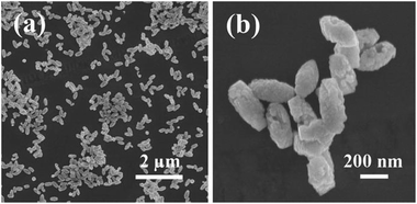
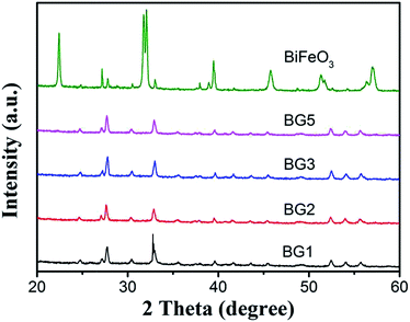
The morphology of BiFeO3 nanostructures were assessed by SEM, as depicted in Fig. 1. From Fig. 1a, it can be easily found that BiFeO3 is comprised of many spindle-like particles with relatively uniform size distribution. The high magnification SEM images displayed in Fig. 1b showed that the BiFeO3 spindles are consist of large amounts of small particles and the surfaces are quite rough. The width and length of those spindle-like particles are ca. 200 nm and ca. 400 nm, respectively.The crystal phase of the photocatalysts is determined by XRD, as shown in Fig. 2. For BiFeO3 without rGO added, the diffraction peaks can be indexed on the basis of a BiFeO3 rhombohedral phase with the space group R3c (JCPDS card no. 86-1518), a slight impurity phases can be observed. Interestingly, the presence of rGO in Bi25FeO40/rGO nanocomposites preferentially induces the formation of the sillenite-type phase of Bi25FeO40 (JCPDS card no. 46-0416). Bi25FeO40 is an important member of the ternary metal oxides with a body-centered cubic crystal structure (space group I23 with cell parameter of about 1.018 nm).29 Previous report has proved the existence of dipole moment in the Bi25FeO40 crystal structure, which may enhance the electron–hole separation.30 Thanks to high content of acidic oxygen-containing functionality, the presence of rGO could resulted in affected acidity of the aqueous solution, which eventually suppressed the generation of iron oxide.31 Jiang et al. have found that sillenite-type phase Bi25FeO40 with a relatively low Fe content was obtained. Hence, sillenite-type phase Bi25FeO40 was preferentially formed.
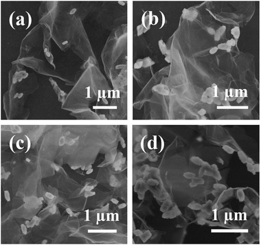
After hybridization of rGO, the rhombohedral BiFeO3 phase disappeared and transformed to the sillenite Bi25FeO40 phase. Interestingly, the morphology of Bi25FeO40 kept well. The SEM images of Bi25FeO40/rGO nanocomposites are displayed in Fig. 3. The spindle-like Bi25FeO40 nanoparticles were randomly attached to the surface of rGO nanosheets which resemble crumpled silk veil waves. When adding rGO, the agglomeration of Bi25FeO40 can be effectively avoided. The images also imply that more and more spindles located at the nanosheets surface while continuously increasing the amount of BiFeO3 powders in the synthesis process. The Bi25FeO40 spindles maintained their highly irregular and rough surfaces, which can magnify the surface area of the catalyst resulting in higher photocatalytic activity.
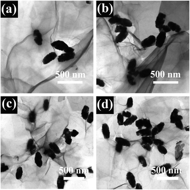
Similar results are elucidated from TEM analysis, as shown in Fig. 4. The Bi25FeO40 spindles dispersed well in the rGO matrix which consist of corrugated and transparent sheets. The rGO nanosheets, where spindles are wrapped in, preferred to wrinkle up. It clearly showed that the Bi25FeO40 spindles featured a size of 300–400 nm anchored uniformly on both sides of the rGO nanosheets. Some Bi25FeO40 spindles were encapsulated within the rGO sheets, which can efficiently prevent the aggregation of particles. The results also revealed rGO as a rather thin microstructure, which enhanced the specific surface ratio.32 The rGO nanosheets interconnected with each other to form an open pore system, which suppressed the dissolution and agglomeration of particles, thereby promoting the stability of the composites.33,34
In order to confirm the valence of some elements in the products, XPS analyses were carried out. Fig. 5a shows a typical wide-scan XPS spectrum, in which all peaks can be assigned to Bi, Fe, O and C elements. Fig. 5b depicts the fine XPS spectrum of Bi 4f, the peaks at 159.3 eV and 164.5 eV can be attributed to the binding energies of Bi 4f7/2 and Bi 4f5/2 in Bi25FeO40, which reveal that Bi is in the Bi3+ oxidation state. As shown in Fig. 5c, the Fe 2p spectra doublet consist of two peaks of Fe 2p3/2 (710.7 eV) and Fe 2p1/2 (724.7 eV), which corresponding to the characteristics of Fe3+ ions. In Fig. 5d, the peak of O 1s at 530.1 eV and 532.5 eV should be assigned to the binding energies of O in the Fe–O and Bi–O chemical bonds, respectively.
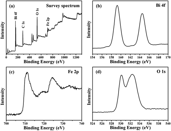 | ||
| Fig. 5 The XPS spectra of (a) full survey of Bi25FeO40/rGO, (b) Bi 4f core levels of Bi25FeO40/rGO, (c) Fe 2p core levels of Bi25FeO40/rGO and (d) O 1s core levels of Bi25FeO40/rGO. | ||
3.2. Optical and photocatalytic performance
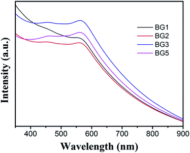
The optical properties of the as-prepared Bi25FeO40/rGO nanocomposites were measured by UV-vis diffuse reflectance spectroscopy (DRS). As can be seen from Fig. 6, all the samples showed strong and broad absorption in the range of 350–600 nm, which indicated that Bi25FeO40/rGO nanocomposites could response to visible light. It can be seen that the absorbance peak in the visible region of BG3 samples is stronger than that of the other nanocomposites. Furthermore, the absorption spectrum of the BG3 sample shows an obvious red-shift trend compared with that of other samples.The photocatalytic degradation of methyl orange (MO) aqueous solution under visible light irradiation was detected to evaluate the photocatalytic performance of Bi25FeO40/rGO nanocomposites and the results are shown in Fig. 7. The suspension was placed in the dark for 1 h with magnetic stirring before irradiation to reach the adsorption/desorption equilibrium. It is observed that MO degradation is negligible in the absence of the photocatalyst. The photocatalytic degradation efficiencies are calculated to be 48% for BiFeO3 after three hours of irradiation. By comparison, the degradation efficiency of Bi25FeO40/rGO nanocomposites is increased to 74% for BG1 and reaches the maximum value of 88% for BG3 under the same experimental conditions, which are much higher than the pure BiFeO3 photocatalyst. The enhancement of the photocatalytic performance should be mainly ascribed to the increase of the light absorption in the Bi25FeO40/rGO nanocomposites for the interfacial structure,35–37 which can reduce the recombination rate of photogenerated electrons and holes.
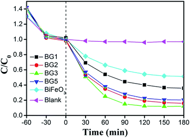 | ||
| Fig. 7 Photocatalytic activity of different catalysts for the degradation of MO solution at room temperature. | ||
In addition to the photocatalytic efficiency, the stability and recyclability of a photocatalyst was also very important from the point of view of its practical application. The sample of BG3 was selected to evaluate the reusability under the same reaction conditions. From Fig. 8, the BG3 photocatalyst shows a good catalytic stability after four recycles. The slight decrease could be attributed to the inescapable loss of catalyst during the recycling process. The result indicated that photocatalysts based on Bi25FeO40/rGO nanocomposites could be reused completely for wastewater treatment.
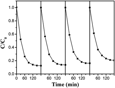 | ||
| Fig. 8 Recyclability of the Bi25FeO40/rGO photocatalyst in four successive experiments for the photocatalytic degradation of MO under visible light irradiation. | ||
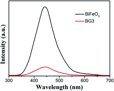
Fig. 9 displays the photoluminescence (PL) spectra of the as-prepared BiFeO3 and the Bi25FeO40/rGO nanocomposites excited by 568 nm. The main emission peak is centered at about 440 nm for the pure BiFeO3 sample. Compared with BiFeO3, the PL spectra intensity of the Bi25FeO40/rGO nanocomposites is significantly decreased in the same position, which indicated that the photogenerated charges recombination rate in Bi25FeO40/rGO composites was much lower than that in BiFeO3 samples. That is, the photogenerated electron–hole pairs can efficiently transfer at the interface of Bi25FeO40/rGO composites, resulting in the highest photocatalytic activity under visible light irradiation.
The enhancement of the photocatalytic activity should be mainly attributed to the increase of the light absorption and the synergistic effect in the Bi25FeO40/rGO nanocomposites, a proposed mechanism is discussed as shown in Fig. 10. Under visible light irradiation, Bi25FeO40 and rGO can be excited to create free electrons and holes. The photogenerated electrons in Bi25FeO40/rGO can easily move towards the surface of rGO sheets. The conjugated sp2-hybridized structure of rGO composite materials provides abundance of delocalized electrons to enhance the transport of photogenerated electrons.38 Accordingly, the superoxide anion radicals are formed in rGO sheets by a reaction between photoinduced electrons and adsorbed oxygen, while the hydroxyl radicals are formed in the Bi25FeO40 surface by a reaction between photoinduced holes and water.39 Hence, MO molecules were degraded by serials reactions with holes, superoxide anion radical and hydroxyl radical.31 One other important role in enhancing the photocatalytic efficiency is the surface area of catalyst. The specific surface area for BG3 was determined by BET (Brunauer–Emmett–Teller) measurements and the result showed that the specific surface area is 7.945 m2 g−1. The effective surface area which organic dyes are in direct contact with catalyst could increase the adsorption of holes. Bi25FeO40 nanoparticles are well spread over the rGO sheets with very minor agglomeration, as shown in Fig. 4. As a result, the photogenerated electrons and holes are efficiently separated between Bi25FeO40 and rGO, which reduces the electron–hole recombination in the hybrid composite photocatalysts.40 Meanwhile, O2 absorbed on the surface of rGO could capture e− and form ˙O2− which then oxidized MO directly on the surface. Both of these two predominance lead to an increase in the photo-conversion efficiency of the hybridized photocatalyst.
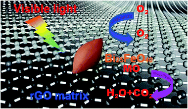 | ||
| Fig. 10 The proposed photocatalytic mechanism for MO degradation over the Bi25FeO40/rGO nanocomposites. | ||
4. Conclusions
In conclusion, Bi25FeO40/rGO photocatalysts with varied Bi25FeO40 contents were synthesized by a liquid phase approach. At room temperature, a phase transition from rhombohedral BiFeO3 to sillenite Bi25FeO40 took place with adding rGO in the solution, while the spindle-like structures were maintained after the reaction. The improved photo-degradation activity toward methyl orange can be mainly ascribed to the structural characteristics of sillenite type Bi25FeO40 and the great charge mobility of rGO, which retard the recombination of photoexcited pairs. Therefore, the Bi25FeO40/rGO nanocomposite is a promising photocatalytic material for environmental applications as well as water splitting.Acknowledgements
We acknowledge the financial support from the Ministry of Education of China (No. IRT1148), Jiangsu Synergistic Innovation Center for Advanced Materials (SICAM), the Project Funded by the Priority Academic Program Development of Jiangsu Higher Education Institutions (PAPD, YX03001), the National Natural Science Foundation of China (51372119, 61377019, 61136003, 51173081, 51602161), College Postgraduate Research and Innovation Project of Jiangsu Province (KYLX_0794, KYLX15_0848), the Natural Science Foundation of Jiangsu Province (KZ0070715050), the Seed Project Funded by Introducing Talent of NJUPT (XK0070915022) and the Natural Science Foundation of NJUPT (NY214129, NY214130, NY214181, NY215176, NY215077).Notes and references
- J. Wang, J. B. Neaton, H. Zheng, V. Nagarajan, S. B. Ogale, B. Liu, D. Viehland, V. Vaithyanathan, D. G. Schlom, U. V. Waghmare, N. A. Spaldin, K. M. Rabe, M. Wuttig and R. Ramesh, Science, 2003, 299, 1719–1722 CrossRef CAS PubMed.
- B. Sun and C. M. Li, Phys. Chem. Chem. Phys., 2015, 17, 6718–6721 RSC.
- D. P. Dutta, O. D. Jayakumar, A. K. Tyagi, K. G. Girija, C. G. S. Pillaia and G. Sharma, Nanoscale, 2010, 2, 1149–1154 RSC.
- S. V. Vijayasundaram, G. Suresh, R. A. Mondal and R. Kanagadurai, J. Alloys Compd., 2016, 658, 726–731 CrossRef CAS.
- W. W. Mao, X. F. Wang, Y. M. Han, X. A. Li, Y. T. Li, Y. F. Wang, Y. W. Ma, X. M. Feng, T. Yang, J. P. Yang and W. Huang, J. Alloys Compd., 2014, 584, 520–523 CrossRef CAS.
- W. W. Mao, X. F. Wang, L. Chu, Y. Y. Zhu, Q. Wang, J. Zhang, J. P. Yang, X. A. Li and W. Huang, Phys. Chem. Chem. Phys., 2016, 18, 6399–6405 RSC.
- T. Choi, S. Lee, Y. J. Choi, V. Kiryukhin and S. W. Cheong, Science, 2009, 324, 63–66 CrossRef CAS PubMed.
- Z. X. Li, Y. Shen, Y. H. Guan, Y. H. Hu, Y. H. Lin and C. W. Nan, J. Mater. Chem. A, 2014, 2, 1967–1973 CAS.
- F. Gao, X. Y. Chen, K. B. Yin, S. Dong, Z. F. Ren, F. Yuan, T. Yu, Z. Zou and J. M. Liu, Adv. Mater., 2007, 19, 2889–2892 CrossRef CAS.
- J. An, L. Zhu, N. Wang, Z. Song, Z. Yang, D. Du and H. Tang, Chem. Eng. J., 2013, 219, 225–237 CrossRef CAS.
- Z. X. Li, Y. Shen, C. G. Yang, Y. C. Lei, Y. H. Guan, Y. H. Lin, D. B. Liu and C. W. Nan, J. Mater. Chem. A, 2013, 1, 823–829 CAS.
- B. Sun, L. J. Wei, H. W. Li and P. Chen, J. Mater. Chem. C, 2014, 2, 7547–7551 RSC.
- X. F. Wang, W. W. Mao, J. Zhang, Y. M. Han, C. Y. Quan, Q. X. Zhang, T. Yang, J. P. Yang, X. A. Li and W. Huang, J. Colloid Interface Sci., 2015, 448, 17–23 CrossRef CAS PubMed.
- M. Ahmadzadeh, A. Ataie and E. Mostafavi, J. Alloys Compd., 2015, 622, 548–556 CrossRef CAS.
- Y. Q. Zheng, G. Q. Tan, H. Y. Miao, A. Xia and H. J. Ren, Mater. Lett., 2011, 65, 1137–1140 CrossRef CAS.
- Z. X. Li, Y. Shen, Y. H. Guan, Y. H. Hu, Y. H. Lin and C. W. Nan, J. Mater. Chem. A, 2014, 2, 1967–1973 CAS.
- X. Yang, G. Xu, Z. H. Ren, X. Wei, C. Y. Chao, S. Y. Gong, G. Shen and G. R. Han, CrystEngComm, 2014, 16, 4176–4182 RSC.
- M. T. Borowiec, A. Majchrowski, J. Zmija, H. Szymczak, T. Zayarniuk, E. Michalski and M. Baranski, Solid State Crystals 2002: Proc. SPIE, 2003, vol. 5136, pp. 26–30 Search PubMed.
- J. M. Li, J. Y. Song, J. G. Chen, S. W. Yu, D. R. Jin and J. R. Cheng, Mater. Res. Soc. Symp. Proc., 2010, 1217, 1217 Search PubMed.
- L. Zhang, X. Zhang, Y. Zou, Y. H. Xu, C. L. Pan, J. S. Hu and C. M. Hou, CrystEngComm, 2015, 17, 6527–6537 RSC.
- L. Zhang, Y. Zou, J. Song, C. L. Pan, S. D. Sheng and C. M. Hou, RSC Adv., 2016, 6, 26038–26044 RSC.
- G. Q. Tan, Y. Q. Zheng, H. Y. Miao, A. Xia and H. J. Ren, J. Am. Ceram. Soc., 2012, 95, 280–289 CrossRef CAS.
- X. F. Wang, W. W. Mao, Q. X. Zhang, Q. Wang, Y. Zhu, J. Zhang, T. Yang, J. P. Yang, X. A. Li and W. Huang, J. Alloys Compd., 2016, 667, 288–293 CrossRef.
- P. Li, Q. Chen, Y. Y. Lin, G. Chang and Y. B. He, J. Alloys Compd., 2016, 672, 497–504 CrossRef CAS.
- Y. H. Li, Y. J. Sun, F. Dong and W. K. Ho, J. Colloid Interface Sci., 2014, 436, 29–36 CrossRef CAS PubMed.
- Y. Zhou, X. J. Zhang, Q. Zhang, F. Dong, F. Wang and Z. Xiong, J. Mater. Chem. A, 2014, 2, 16623–16631 CAS.
- T. Xiong, F. Dong, Y. Zhou, M. Fu and W. K. Ho, J. Colloid Interface Sci., 2015, 447, 16–24 CrossRef CAS PubMed.
- W. S. Hummers and R. E. Offeman, J. Am. Chem. Soc., 1958, 80, 1339 CrossRef CAS.
- Y. Du, Z. Cheng, Z. Yu, S. X. Dou, X. Wang and L. Q. Liu, J. Nanosci. Nanotechnol., 2012, 12, 1684–1687 CrossRef CAS PubMed.
- J. B. Lu, Y. Dai, Y. T. Zhu and B. B. Huang, ChemCatChem, 2011, 3, 378–385 CrossRef CAS.
- A. W. Sun, H. Chen, C. Y. Song, F. Jiang, X. Wang and Y. S. Fu, RSC Adv., 2013, 3, 4332–4340 RSC.
- L. K. Pan, X. J. Liu, Z. Sun and C. Q. Sun, J. Mater. Chem. A, 2013, 1, 8299–8326 CAS.
- Z. S. Wu, Y. Sun, Y. Z. Tan, S. B. Yang, X. L. Feng and K. Müllen, J. Am. Chem. Soc., 2012, 134, 19532–19535 CrossRef CAS PubMed.
- L. Xiao, D. Q. Wu, S. Han, Y. S. Huang, S. Li, M. Z. He, F. Zhang and X. L. Feng, ACS Appl. Mater. Interfaces, 2013, 5, 3764–3769 CAS.
- K. Woan, G. Pyrgiotakis and W. Sigmund, Adv. Mater., 2009, 21, 2233–2239 CrossRef CAS.
- A. S. Zhu, Q. D. Zhao, X. Y. Li and Y. Shi, ACS Appl. Mater. Interfaces, 2014, 6, 671–679 CAS.
- S. Cong and Y. Xu, J. Phys. Chem. C, 2011, 115, 21161–21168 CAS.
- S. M. Sun and W. Z. Wang, RSC Adv., 2014, 4, 47136–47152 RSC.
- Y. Wu, H. J. Luo, X. L. Jiang, H. Wang and J. J. Geng, RSC Adv., 2015, 5, 4905–4908 RSC.
- L. Y. Huang, H. Xu, Y. P. Li, H. M. Li, X. N. Cheng, J. X. Xia, Y. G. Xu and G. B. Cai, Dalton Trans., 2013, 42, 8606–8616 RSC.
| This journal is © The Royal Society of Chemistry 2017 |

