 Open Access Article
Creative Commons Attribution 3.0 Unported Licence
Removal of NaCl from saltwater solutions using micro/mesoporous carbon sheets derived from watermelon peel via deionization capacitors†
Shanshan Zhao,
Tingting Yan,
Zhuo Wang,
Jianping Zhang,
Liyi Shi and
Dengsong Zhang *
*
Research Center of Nano Science and Technology, Shanghai University, Shanghai 200444, China. E-mail: dszhang@shu.edu.cn
First published on 16th January 2017
Abstract
Micro/mesoporous carbon sheets with high specific surface area (up to 2360 m2 g−1) were successfully prepared by using watermelon peel as a carbon source through a simple activation method and were originally developed as highly efficient electrodes for flow-through deionization capacitors to remove NaCl from saltwater solutions. The carbon source is low-cost and the approach is very simple, effective and environmentally-friendly. Owing to the micro/mesoporous structure and high specific area, the obtained electrode presents a superior wettability and good electrochemical performance. In the deionization experiments, the electrodes show a high deionization capacity of 17.38 mg g−1 at 1.2 V in a 500 mg L−1 NaCl solution. Besides, the electrodes possess a high deionization rate at 0.8–1.4 V in 100–500 mg L−1 NaCl solutions. The electrodes also present a good regeneration behavior. The good performance makes the electrodes promising candidates for flow-through deionization capacitors. We also hope that the micro/mesoporous carbon sheets can be applied to other areas.
1. Introduction
The freshwater shortage has become a serious problem limiting human development,1,2 therefore finding effective methods to produce freshwater is quite urgent. Seawater desalination attracts great interest. Membranes, reverse osmosis and electrodialysis are the most used methods. However, these methods always suffer from such disadvantages as excessive energy-consumption, high cost and secondary pollution.3 Capacitive deionization is an emerging technology for seawater and brackish water desalination using a flow-through deionization capacitor (FTDC). The FTDC is based on the principle of electric double layer capacitors (EDLCs). When a cell voltage is added, the electrodes would be charged, and the ions would move towards the electrodes and then be adsorbed on the electric double layer (EDL) formed between the electrode interface and the solution. After the cell voltage is removed, the ions can be desorbed immediately.4–6 The FTDC has such advantages as low energy-consumption, high efficiency and environmental friendliness.7,8The properties of electrode material play a vital role in the FTDC.9 Activated carbon,10–12 carbon aerogels,13–15 graphene,16,17 carbon nanotubes,18,19 mesoporous carbon,20,21 carbon nanofibers22–24 and their composites25–28 are widely used as FTDC electrode materials today. Among them, activated carbons attract great interest due to low cost, high specific surface area and environmental compatibility.29 However, the pore structure of activated carbons are mainly composed of micropores, which restricts the ion diffusion and not beneficial to the deionization process.30 Mesoporous carbons have numerous of mesopores, which would be in favor of the salt ions transporting31,32 and thus show a higher deionization capacity than activated carbon.20 Porous carbon with different pore size distribution combines the advantages of different pore structures and thus shortens the ion transport pathway, reduce the resistance and provide larger accessible surface area for salt ions. It has been demonstrated that the porous carbon materials with different pore structures have shown excellent performance in electrochemistry31–34 and also have been used as FTDC electrodes.35–37
Recently, biomass derived carbon materials are gaining increasing attention due to their advantages of easy to get, facile to prepare, low-cost, effectiveness and environmentally friendly. Up to now, some biomass materials such as soybeans,29 eggplants,38,39 leaves,40 banana peel,41 seed shells,42,43 fungi,44 seaweeds45–47 and coffee beans48 have been applied to prepare porous carbon and the obtained carbon materials have shown good performance in many areas such as supercapacitors, lithium batteries and oxygen reduction reaction. Watermelon is a common fruit anywhere. The peel is always been thrown away. It is interesting that carbon materials could be obtained from watermelon peel.49,50 As far as we know, no work about watermelon peel-derived carbon as electrode materials for FTDC is reported so far.
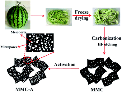
In this work, we prepared micro/mesoporous carbon sheets (MMC-A) with high specific surface area using watermelon peels as carbon source through a simple activation approach and originally developed as highly efficient electrodes for flow-through deionization capacitors to remove NaCl from saltwater solutions. Fig. 1 illustrates the preparation of the MMC-A. The watermelon peel was first freeze dried and then carbonized. After etching with HF in order to remove the impurity, the micro/mesoporous carbon (MMC) was obtained. Finally, a simple KHCO3 activation process was employed to obtain the MMC-A. The KHCO3 can decompose when heated and generate gases including CO2 and CO, which could enlarge the size of a portion micropores and render them become mesopores. The activator and gases can also react with carbon and these reactions contribute to the formation of another portion of mesopores and micropores. As a result, numerous mesopores, micropores and high specific surface area are all obtained. These characteristics provide the MMC-A larger accessible surface area, more convenient transporting pathways and good wettability. The MMC-A electrode has a good electrochemical performance. The MMC-A electrodes also exhibits a high deionization capacity, fast deionization rate and good regeneration behavior.
2. Experimental section
2.1 Materials
All chemicals were purchased by Sinopharm Chemical Reagent Co., Ltd. The watermelon was purchased from Wal-Mart supermarket (Qilian Road, Shanghai, P. R. China).2.2 Preparation
Watermelon peels were first cut into chips shape using a fruit knife and then freeze-dried for dozens hours. The dried peel was then calcined at 800 °C for 3 h (5 °C min−1). The obtained black sample was ground into powder and washed by 10% of HF in order to remove the impurity. After washed by deionized water and dried, the prepared sample was mixed with KHCO3 (the ratio of carbon to KHCO3 is 1![[thin space (1/6-em)]](https://www.rsc.org/images/entities/char_2009.gif) :
:![[thin space (1/6-em)]](https://www.rsc.org/images/entities/char_2009.gif) 8) in deionized water and the mixture was evaporate to dryness at 60 °C. Afterwards, the dried mixture was heated at 600, 700 and 800 °C for 3 h (5 °C min−1). The resulting sample was then washed using a 2 mol L−1 HCl solution so as to remove the inorganic impurity. Finally, the black samples were obtained after drying at 60 °C. The obtained black carbon materials were named as MMC-A-x, where x is the calcination temperature. For comparison, the MMC was prepared by direct calcining the watermelon peels and etching with HF without the activation process.
8) in deionized water and the mixture was evaporate to dryness at 60 °C. Afterwards, the dried mixture was heated at 600, 700 and 800 °C for 3 h (5 °C min−1). The resulting sample was then washed using a 2 mol L−1 HCl solution so as to remove the inorganic impurity. Finally, the black samples were obtained after drying at 60 °C. The obtained black carbon materials were named as MMC-A-x, where x is the calcination temperature. For comparison, the MMC was prepared by direct calcining the watermelon peels and etching with HF without the activation process.
2.3 Characterization
The N2 adsorption–desorption tests were carried out on Autosorb-IQ2 (Quantachrome Corporation). The BET method was applied to calculate the specific surface area. The pore size distribution was obtained from the slit/cylinder pores QSDFT adsorption model. The micropore surface area (Smicro) and the external surface area (Sext) were obtained from t-plot analysis. The samples were then characterized by using SEM on JEOL JEM-6700F, TEM on JEOL JEM-2010F and XRD on Rigaku D/MAX-RB X-ray diffractometer. The wettability of the electrodes was measured using dynamic contact angle analysis on Krüss-DSA100. X-ray photoelectron spectroscopy (XPS) was tested on a Perkin-Elmer PHI 5000C ESCA system equipped with a dual X-ray source, using the MgKα (1253.6 eV) anode and a hemispherical energy analyzer. The CV and EIS tests were carried out on CHI 660D (Chenhua Co., Ltd., Shanghai). The GC analysis was measured on CT2001A (Land Electronic, Wuhan). The three-electrode system was applied during all the process, in which the MMC-A or MMC electrode was used as working electrode, a piece of graphite was used as counter electrode and a saturated calomel electrode was used as reference electrode respectively. The concentration of the NaCl solution is 0.5 M. The specific capacitances were obtained from the equation:51,52
 | (1) |
2.4 Deionization experiments
The electrodes consist of 80 wt% of MMC-A or MMC, 10 wt% of conductive carbon black and 10 wt% of binder (PTFE). The obtained slurries were pressed on the graphite paper. The obtained electrodes were then dried at 120 °C overnight. The mass of the electrodes were 0.2 g. The size of the electrodes were 5 cm × 5 cm. The thickness of the electrodes was 0.2 mm. Finally the electrodes were equipped into the deionization device with a continuously recycling system to test the deionization performance (Fig. S1†). The FTDC device consists of two electrodes, which are separated by a piece of insulating grid spacer. With the help of the peristaltic pump, the NaCl solution can flow through the device circularly. The device was equipped with a conductivity meter, which can measure the conductivity value of NaCl solution in real-time. The volume of NaCl solution is 30 mL. The flow rate of the NaCl solutions was 40 mL min−1. The concentration of the NaCl solutions was 100–500 mg L−1. The applied voltages were 0.8–1.4 V.The salt adsorption capacity (SAC) of the FTDC electrodes were obtained from the formula (2):25,53
| SAC = (C0 − C)V/m | (2) |
The charge efficiency (Λ) is obtained from the formula (3):16,54
| Λ = (Γ × F)/Σ | (3) |
![[thin space (1/6-em)]](https://www.rsc.org/images/entities/char_2009.gif) 485C mol−1) and Σ (charge, C g−1) is calculated through integrating the current.
485C mol−1) and Σ (charge, C g−1) is calculated through integrating the current.
3. Results and discussion
3.1 Characteristics
The activation temperature is a key factor that determines the specific surface area and pore size. Fig. 2a depicts the nitrogen sorption isotherms of all the samples. All the isotherms exhibit similar type that can ascribed to the mixture of type I (b) and type IV (a) with the type H4 hysteresis loops, according to the IUPAC Technical Report.55 At low relative pressure, the curves are very steep, implying the existence of micropores.54 The broad hysteresis loops appear at high relative pressure proves the existence of mesoporous structure.34 From the MMC to MMC-A, the adsorbed volume is increased notably, elucidating the enhanced specific surface area and pore volume. Fig. 2b depicts the pore size distributions of all the samples. The pore size is mainly centered at the range of ∼0.50–33 nm, indicating they have both micropores and mesopores. For MMC, a sharp peak appears at 0.52 nm indicates the MMC is micropores dominated. After activation, the intensities of peaks situated at the micropore range are much lower and at the mesopore range are stronger, indicating the increase of the mesopores. For MMC-A-800, the peaks mainly situated at 0.57, 0.85, indicating it has a large portion of micropores. From the inset in Fig. 2b, the MMC-A exhibits peaks at 2.43, 2.70, 3.01 and 3.94 nm, which can prove that the MMC-A has mesopores. Table 1 exhibits the surface texture properties of all the samples. The MMC has the lowest specific surface area and pore volume (872 m2 g−1, 0.43 cm3 g−1). After activation, the specific surface area is increased. Moreover, with the activation temperature increased, the specific surface area and pore volume are all enhanced correspondingly. The reason is that at higher temperature, the activation process would occur more completely. The MMC-A-800 has the highest specific surface area and the highest pore volume (2360 m2 g−1 and 1.31 cm3 g−1). It should be noted that the micropore surface area of the MMC-A-600, MMC-A-700 and MMC-A-800 are rather similar while the external surface area of the MMC-A-800 is significantly higher than that of the MMC-A-600 and MMC-A-700. This is mainly because that during the activation process, a series of reactions would take place as indicated in the eqn (4)–(8).31,56–58 At about 200 °C, KHCO3 would decompose as listed in the eqn (4). When the temperature exceeds to 400 °C, the eqn of (5)–(8) would take place.59 In addition, when the temperature get increased, the decomposition rate would be quicker, and this is also beneficial to enlarging the pore size.31 In consideration that the MMC-A-800 has a large amount of micropores and mesopores, we choose the MMC-A-800 as the sample to study the electrochemical and deionization performance. For convenience sake, the MMC-A-800 is named as MMC-A in the following text.| 2KHCO3 → K2CO3 + CO2 + H2O | (4) |
| K2CO3 → K2O + CO2 | (5) |
| K2CO3 + 2C → 2K + 3CO | (6) |
| K2O + C → 2K + CO | (7) |
| CO2 + C → 2CO | (8) |
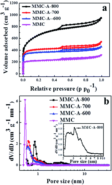 | ||
| Fig. 2 (a) Nitrogen sorption isotherms and (b) pore size distributions of all the samples. The inset is the pore distribution of MMC-A-800 in the pore range of 2–10 nm. | ||
| Samples | SBET (m2 g−1) | Smicro (m2 g−1) | Sext (m2 g−1) | Vtotal (cm3 g−1) | Dmax (nm) |
|---|---|---|---|---|---|
| MMC-A-800 | 2360 | 1301 | 1059 | 1.31 | 0.85 |
| MMC-A-700 | 1611 | 1313 | 298 | 0.71 | 0.61 |
| MMC-A-600 | 1431 | 1181 | 250 | 0.62 | 0.61 |
| MMC | 872 | 650 | 222 | 0.43 | 0.52 |
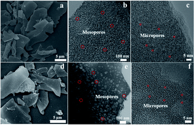
The freeze-dried watermelon peel shows fold and sponge-like shape (Fig. S2a†). After calcination, the obtained carbon presents a sheet-like shape before HF etching (Fig. S2b†). Fig. 3 shows the SEM and TEM images of the MMC-A and MMC. From Fig. 3a and d, no obvious difference can be seen from the SEM images of the MMC-A and MMC. They both exhibit sheet-like shape and the size of the sheets is about several micrometers. From Fig. 3b and e we can see that both MMC-A and MMC have a large number of mesopores. Furthermore, after the activation, the resulting MMC-A show richer porosity than the MMC. From Fig. 3c and f, a large number of micropores can be easily identified from both MMC-A and MMC. In comparison to the MMC, the MMC-A have more micropores and mesopores. The considerable number of micropores can provide larger accessible surface area for salt ions. The mesopores can reduce the ion transport resistance.
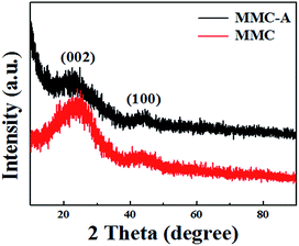
After carbonized, the pristine carbon consists of some crystalline inorganic compounds, including SiO2 and some impurities might containing potassium, chlorine, fluorine and oxygen40 (Fig. S3†) and thus the HF etching is necessary. Fig. 4 displays the XRD patterns of the MMC-A and MMC, which reflects the crystallinity and purity of the samples. Two broad diffraction peaks appear at a 2θ value of ∼23° and ∼45°, which were assigned to the characteristic carbon (002) and (100) diffractions, respectively.60 Moreover, no diffractions peaks of impurity can be observed, suggesting that the samples are highly pure. The intensity of (002) peak of the MMC-A is weaker than that of MMC, indicating the MMC-A has poorer graphitization degree and more defection due to the activation process and its richer porosity.61
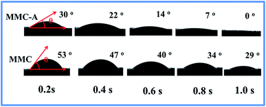
To study the wettability of the MMC-A and MMC electrodes, dynamic contact angle measurements were carried out and the optical micrographs are shown in Fig. 5. At the beginning of the test, the contact angle of MMC-A is 30° while the MMC has a wider angle of 53°. As time goes on, the angle of the MMC-A electrode was decreased fast and the water droplet diffuse into the inner pores of the MMC-A electrode completely at the contact time of 1 s. In contrast, the MMC still remains a wide angle of 29°. According to the XPS analysis (Fig. S4†), the content of the surface functional groups of the MMC-A and MMC is quite close, and it can be concluded that the improved wettability of the MMC-A is its richer porosity, micro/mesoporous structure and higher specific surface area. A good wettability would lead to a sufficient contact between the electrodes and solution, which is beneficial to salt solution in filtration, and thus enhance the salt adsorption performance.62
3.2 Electrochemical performance
CV tests were applied to evaluate potential applications of the MMC-A and MMC for FTDC. Fig. 6a shows the CV profiles of the electrodes at 1 mV s−1 in a 0.5 M NaCl solution. Both profiles have no any oxidation and reduction peak, indicating the capacitance behavior mostly results from the ideal EDLC behavior at the salt solution–electrode interface rather than faradaic reaction.63 In addition, the curves are very symmetrical, suggesting the electrodes have a good reversible ion adsorption–desorption behavior. It also can be seen that the CV curves have slight deviation from rectangular shape and the main reason for the deviation is the inherent resistivity of the salt solutions.64 The specific capacitance of the MMC-A electrode calculated from eqn (1) is 224 F g−1, which is higher than the MMC electrode (176 F g−1). The enhanced specific capacitance is due to the richer porosity, higher specific surface area and better wettability. Moreover, the CV curves of the MMC-A and MMC electrodes at 1 mV s−1 in a 500 mg L−1 NaCl solution (the same as the deionization experiment condition) have no any oxidation and reduction peak (Fig. S5†), indicating that the electrodes would not take any place Faradaic reaction during deionization process.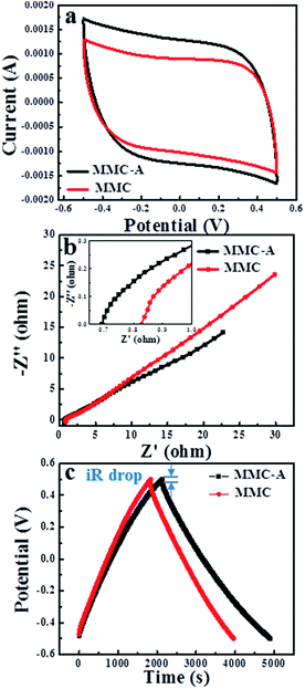 | ||
| Fig. 6 (a) CV curves of the electrodes at 1 mV s−1; (b) Nyquist profiles of the electrodes; (c) GC curves of the electrodes at 200 mA g−1. The curves were all obtained in 0.5 M NaCl solution. | ||
The Nyquist plots are also depicted. As shown in Fig. 6b, two profiles exhibit a similar shape. A semicircle and a slop line can be seen in the high frequency and low frequency, respectively. The diameter of the semicircle always indicates the polarization resistance, which reflects the charge-transfer resistance between the electrodes and the solution interface.65 Clearly, both two diameters are very small, indicating the charge transfer resistance of the electrodes is negligible. The x-intercept of the plots reflect the equivalent series resistance (ESR), which related to the inner resistance, including the electrodes resistance, ionic resistance of salt solution and contact resistance between the carbon materials and the current collectors.66 Generally speaking, a smaller value of ESR always indicates a smaller internal resistance.67 The ESR value of the MMC-A electrode is 0.69, which is lower than MMC electrode and some other carbon material,68 suggesting the MMC-A possesses smaller impedance and better conductivity. The line in the low frequency indicates the capacitive behaviors of electrodes.69 The plots of the MMC-A and MMC electrodes have a similar line shape, indicating they have similar capacitive behavior. To sum up, the MMC-A electrode possesses low internal resistance and good conductivity. This is because that the MMC-A have more mesopores and micropores, and thus form a denser pore network, which can facilitate the salt ion diffusion and thus decreasing the resistance. In contrast, the MMC possess a fewer pore structures and mainly consisting of micropores, which hinder the ion diffusion and result in a greater resistance. The EIS results demonstrate that the MMC-A electrode have more easier transport pathways for salt ions and is more suitable for the FTDC.
Fig. 6c shows the GC profiles of the MMC-A and MMC electrodes. The profiles show a triangular shape, indicating an ideal EDLC behavior with no Faradaic reaction.70,71 The curves show liner potential–time plots at the same time, suggesting the rapid i–V response.72 Furthermore, the discharge time of the MMC-A electrode is longer than MMC electrode, suggesting that the MMC-A electrode has a higher specific capacitance, which corroborates the CV results. However, the GC curves are not perfectly triangular and this is mainly because of the inherent resistivity of the salt solutions.64 It should be noted that the iR drop can be observed at the start of discharge profiles during the GC process, which reveals the resistance of the solution, electrodes and ion diffusion.37 The MMC-A electrode shows an iR drop of 0.02 V, which is smaller than MMC electrode (0.03 V), suggesting that the MMC-A electrode has lower resistance, which is accord with the EIS results. In brief, the pore structures of MMC-A electrode are more convenient for salt ions to transport, which forebode that the MMC-A electrodes should have good deionization performance.
3.3 Deionization performance
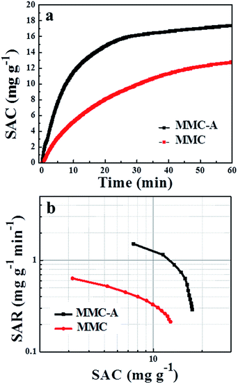
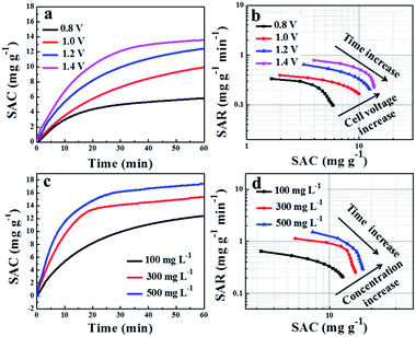
The deionization experiments of the MMC-A and MMC electrodes were carried out in a 500 mg L−1 NaCl solution at 1.2 V. From Fig. 7a, with the time increased within 30 min, the conductivity of the electrodes decreases notably. Correspondingly, the SAC plot of the electrodes increase markedly. The plot of the MMC-A electrodes is more steep than MMC electrode, indicating the salt adsorption process of the MMC-A electrodes is faster. Then the plots become smooth. After 60 min, the SAC of the MMC-A electrodes reaches to 17.38 mg g−1, which is better than the MMC electrodes (12.77 mg g−1). In addition, the SAC of the MMC-A electrodes is also much higher than the most FTDC electrode materials reported so far (Table S1†), indicating a good salt adsorption performance of the MMC-A electrodes. Salt adsorption rate (SAR) is also very crucial to the electrodes. Ragone plots of SAR vs. SAC for the electrodes was also depicted, which gives a visual representation of the deionization performance.8,73 As presented in Fig. 7b, the plot of MMC-A electrodes is in the righter and upper region, indicating the MMC-A electrodes have a higher SAC and faster SAR. At each concentration, the MMC-A electrodes possess a higher SAC and faster SAR than MMC electrodes (Fig. S6a and b†). To each curve, with the process of the deionization, the SAC becomes higher and the SAR becomes lower. The reason is that with the deionization process goes on, the accessible surface area for salt ions become smaller and smaller. Meanwhile, the ions adsorbed into the EDLC would generate a stronger electrostatic repulsion, which is also not in favor of the deionization. As a result, the SAC remains increasing while the SAR decreases in all the deionization process. In addition, the MMC-A electrodes also presents a good deionization performance in a high NaCl concentration of 1000 mg L−1 (Fig. S7†). The high deionization capacity and fast deionization rate of the MMC-A electrodes can be explained by the following reasons. The MMC-A possess more pores consisting of meso- and micropores. The mesopores can decrease the resistance of the salt ions in transporting process through the porous carbon, and the micropores can provide larger accessible surface area for ions. In addition, the MMC-A have a superior wettability resulting from the higher porosity and hierarchical porous structure, which lead to a sufficient contact between the electrodes and solution and makes the salt ions transporting more quickly and sufficiently.To investigate the impact of the cell voltage on the deionization process, the voltages of 0.8–1.4 V were used to carry out the deionization experiments in a 100 mg L−1 NaCl solution. As shown in Fig. 8a, once the cell voltage was applied, the SAC increases dramatically. At higher voltages, the SAC increase more quickly. From 0.8 V to 1.4 V, the SAC increased from 5.84 mg g−1 to 13.56 mg g−1, indicating a higher cell voltage is in favor of enhancing the deionization capacity. It is also can be seen that the slope of the curve increase with the increase of the cell voltage, indicating the increases of SAR. These results are also can be seen from Fig. 8b, which depicts the Ragone plots of SAR vs. SAC at different cell voltages. With the cell voltage increased, the plot turns righter and upper, indicating a higher SAC and faster SAR. As we know, when the cell voltage increased, the electrostatic forces would be stronger and the EDLC would form more sufficiently and thus would be thicker. As a result, the SAC would be increased and the SAR would be faster.25,73 When the cell voltage increased, the SAC vs. SAR change less, this is because the carbon material has nearly approached the capacity limit.
The deionization performance of the MMC-A electrodes in 100–500 mg L−1 NaCl solutions at 1.2 V were also evaluated. As shown in Fig. 8c, from 100 mg L−1 to 500 mg L−1, the SAC increases from 12.43 mg g−1 to 17.38 mg g−1. In addition, the slop of the curves also increases, indicating the increase of the SAR. Fig. 8d displays the Ragone plots of SAR vs. SAC of the MMC-A electrodes in 100–500 mg L−1 NaCl solutions. Obviously, when the concentration of NaCl solution increases, the plot shift to righter and upper, indicating a higher SAC and faster SAR. The higher SAC is due to that when the concentration increases, the formation of the EDLC would be more effortless. The faster SAR can be explained that with the increase of the NaCl concentration, the conductivity would increase correspondingly, and the transport of ions would be more rapid.73,74 When the concentration of NaCl solution increased, the SAC vs. SAR change less, this is mainly due to that the electrodes have nearly approached the capacity limit.
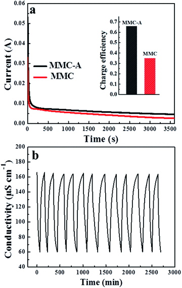
The charge efficiency reflects the ratio of adsorbed salt over charge.8,75 Fig. 9a shows the current transient during the deionization process in a 100 mg L−1 NaCl solution at 1.2 V. The charge efficiencies of the MMC-A and MMC electrodes are calculated to be 0.66 and 0.35, indicating the MMC-A electrodes are more energy-saving, which attributes to that the increased micro- and mesopores are beneficial to the formation of the EDL.8,76 The charge efficiency is always lower than the theoretical value of 1, which is mainly because of the following three reasons: (i) when we prepare the electrodes, the binder with poor conductivity such as PTFE is always used, which would increase the resistance of the electrodes; (ii) the adhesion between the carbon material and graphene paper is not very closely inevitably, which would also consume a part of charge; (iii) during the deionization process, the adsorbed ions would repel each other, which also decreases the charge utilization.8,77
To study the regeneration behavior of the MMC-A electrodes, reiterative salt adsorption–desorption experiments were conducted in a ∼80 mg L−1 NaCl solution through applying charge voltage of 1.2 V and discharge voltage of 0 V. As shown in Fig. 9b, when MMC-A electrodes were charged, the conductivity decreases immediately. Once the voltage is removed, the conductivity increases back to the original value rapidly. In addition, during over 10 regeneration process, the SAC of the MMC-A electrodes almost has no clear declination. In addition, the MMC-A electrodes also present a good regeneration performance in a 150 mg L−1 NaCl solution (Fig. S8†). These results reveal that the MMC-A electrodes have a good regeneration behavior and stability, which further demonstrates that the MMC-A is a promising FTDC electrode material.
4. Conclusions
The micro/mesoporous carbon sheets with high specific surface area was successfully prepared using watermelon peels as carbon source through an activation method and originally developed as highly efficient electrodes for flow-through deionization capacitors to remove NaCl from saltwater solutions. The carbon source is low-cost and the preparation process is very simple, effective and environmentally-friendly. The MMC-A electrode exhibits a superior wettability and good electrochemical performance. The MMC-A electrodes also possess a high deionization capacity, fast deionization rate and good regeneration behavior. Considering these above factors, the MMC-A fairly possess good deionization performance for potential application in the flow-through deionization capacitors. We also hope that the as-prepared MMC-A can be applied to other areas such as supercapacitors, lithium ion batteries, adsorption and others.Acknowledgements
The work was supported by the National Natural Science Foundation of China (U1462110). We also appreciate the Analysis and Test Center of SHU for the sample measurements.References
- M. A. Shannon, P. W. Bohn, M. Elimelech, J. G. Georgiadis, B. J. Marinas and A. M. Mayes, Nature, 2008, 452, 301–310 CrossRef CAS PubMed.
- T. Humplik, J. Lee, S. C. O'Hern, B. A. Fellman, M. A. Baig, S. F. Hassan, M. A. Atieh, F. Rahman, T. Laoui, R. Karnik and E. N. Wang, Nanotechnology, 2011, 22, 292001 CrossRef CAS PubMed.
- H. Yin, S. Zhao, J. Wan, H. Tang, L. Chang, L. He, H. Zhao, Y. Gao and Z. Tang, Adv. Mater., 2013, 25, 6270–6276 CrossRef CAS PubMed.
- S. Porada, L. Borchardt, M. Oschatz, M. Bryjak, J. S. Atchison, K. J. Keesman, S. Kaskel, P. M. Biesheuvel and V. Presser, Energy Environ. Sci., 2013, 6, 3700–3712 CAS.
- T. J. Welgemoed and C. F. Schutte, Desalination, 2005, 183, 327–340 CrossRef CAS.
- M. A. Anderson, A. L. Cudero and J. Palma, Electrochim. Acta, 2010, 55, 3845–3856 CrossRef CAS.
- S. Porada, R. Zhao, A. van der Wal, V. Presser and P. M. Biesheuvel, Prog. Mater. Sci., 2013, 58, 1388–1442 CrossRef CAS.
- M. E. Suss, S. Porada, X. Sun, P. M. Biesheuvel, J. Yoon and V. Presser, Energy Environ. Sci., 2015, 8, 2296–2319 CAS.
- Y. Liu, C. Nie, X. Liu, X. Xu, Z. Sun and L. Pan, RSC Adv., 2015, 5, 15205–15225 RSC.
- M.-W. Ryoo and G. Seo, Water Res., 2003, 37, 1527–1534 CrossRef CAS PubMed.
- J.-H. Choi, Sep. Purif. Technol., 2010, 70, 362–366 CrossRef CAS.
- T. Kim and J. Yoon, J. Electroanal. Chem., 2013, 704, 169–174 CrossRef CAS.
- H.-H. Jung, S.-W. Hwang, S.-H. Hyun, K.-H. Lee and G.-T. Kim, Desalination, 2007, 216, 377–385 CrossRef CAS.
- P. Xu, J. E. Drewes, D. Heil and G. Wang, Water Res., 2008, 42, 2605–2617 CrossRef CAS PubMed.
- M. C. Zafra, P. Lavela, G. Rasines, C. Macías, J. L. Tirado and C. O. Ania, Electrochim. Acta, 2014, 135, 208–216 CrossRef CAS.
- X. Xu, Z. Sun, D. H. Chua and L. Pan, Sci. Rep., 2015, 5, 11225 CrossRef CAS PubMed.
- B. Jia and L. Zou, Carbon, 2012, 50, 2315–2321 CrossRef CAS.
- L. Wang, M. Wang, Z.-H. Huang, T. Cui, X. Gui, F. Kang, K. Wang and D. Wu, J. Mater. Chem., 2011, 21, 18295–18299 RSC.
- M. A. Tofighy and T. Mohammadi, Desalination, 2010, 258, 182–186 CrossRef CAS.
- L. Zou, L. Li, H. Song and G. Morris, Water Res., 2008, 42, 2340–2348 CrossRef CAS PubMed.
- C. Tsouris, R. Mayes, J. Kiggans, K. Sharma, S. Yiacoumi, D. DePaoli and S. Dai, Environ. Sci. Technol., 2011, 45, 10243–10249 CrossRef CAS PubMed.
- A. G. El-Deen, N. A. M. Barakat, K. A. Khalil and H. Y. Kim, J. Mater. Chem. A, 2013, 1, 11001–11010 CAS.
- G. Wang, C. Pan, L. Wang, Q. Dong, C. Yu, Z. Zhao and J. Qiu, Electrochim. Acta, 2012, 69, 65–70 CrossRef CAS.
- A. G. El-Deen, N. A. M. Barakat, K. A. Khalil and H. Y. Kim, New J. Chem., 2014, 38, 198–205 RSC.
- H. Li, L. Pan, C. Nie, Y. Liu and Z. Sun, J. Mater. Chem., 2012, 22, 15556–15561 RSC.
- Q. Dong, G. Wang, B. Qian, C. Hu, Y. Wang and J. Qiu, Electrochim. Acta, 2014, 137, 388–394 CrossRef CAS.
- Y. Wimalasiri and L. Zou, Carbon, 2013, 59, 464–471 CrossRef CAS.
- H. Li, S. Liang, J. Li and L. He, J. Mater. Chem. A, 2013, 1, 6335–6341 CAS.
- C. Long, L. Jiang, X. Wu, Y. Jiang, D. Yang, C. Wang, T. Wei and Z. Fan, Carbon, 2015, 93, 412–420 CrossRef CAS.
- K. Xia, Q. Gao, J. Jiang and J. Hu, Carbon, 2008, 46, 1718–1726 CrossRef CAS.
- J. Deng, T. Xiong, F. Xu, M. Li, C. Han, Y. Gong, H. Wang and Y. Wang, Green Chem., 2015, 17, 4053–4060 RSC.
- M. Rose, Y. Korenblit, E. Kockrick, L. Borchardt, M. Oschatz, S. Kaskel and G. Yushin, Small, 2011, 7, 1108–1117 CrossRef CAS PubMed.
- X. Deng, B. Zhao, L. Zhu and Z. Shao, Carbon, 2015, 93, 48–58 CrossRef CAS.
- L. Qie, W. Chen, H. Xu, X. Xiong, Y. Jiang, F. Zou, X. Hu, Y. Xin, Z. Zhang and Y. Huang, Energy Environ. Sci., 2013, 6, 2497–2504 Search PubMed.
- R. T. Mayes, C. Tsouris, J. O. Kiggans Jr, S. M. Mahurin, D. W. DePaoli and S. Dai, J. Mater. Chem., 2010, 20, 8674–8678 RSC.
- G. Wang, Q. Dong, Z. Ling, C. Pan, C. Yu and J. Qiu, J. Mater. Chem., 2012, 22, 21819–21823 RSC.
- X. Wen, D. Zhang, L. Shi, T. Yan, H. Wang and J. Zhang, J. Mater. Chem., 2012, 22, 23835–23844 RSC.
- B. Li, D. Geng, X. S. Lee, X. Ge, J. Chai, Z. Wang, J. Zhang, Z. Liu, T. S. Hor and Y. Zong, Chem. Commun., 2015, 51, 8841–8844 RSC.
- Z. Li, W. Lv, C. Zhang, B. Li, F. Kang and Q.-H. Yang, Carbon, 2015, 92, 11–14 CrossRef CAS.
- R. Wang, P. Wang, X. Yan, J. Lang, C. Peng and Q. Xue, ACS Appl. Mater. Interfaces, 2012, 4, 5800–5806 CAS.
- Y. Lv, L. Gan, M. Liu, W. Xiong, Z. Xu, D. Zhu and D. S. Wright, J. Power Sources, 2012, 209, 152–157 CrossRef CAS.
- A. Elmouwahidi, Z. Zapata-Benabithe, F. Carrasco-Marin and C. Moreno-Castilla, Bioresour. Technol., 2012, 111, 185–190 CrossRef CAS PubMed.
- X. Li, W. Xing, S. Zhuo, J. Zhou, F. Li, S. Z. Qiao and G. Q. Lu, Bioresour. Technol., 2011, 102, 1118–1123 CrossRef CAS PubMed.
- H. Zhu, X. Wang, F. Yang and X. Yang, Adv. Mater., 2011, 23, 2745–2748 CrossRef CAS PubMed.
- E. Raymundo-Piñero, F. Leroux and F. Béguin, Adv. Mater., 2006, 18, 1877–1882 CrossRef.
- E. Raymundo-Piñero, M. Cadek and F. Béguin, Adv. Funct. Mater., 2009, 19, 1032–1039 CrossRef.
- D. Kang, Q. Liu, J. Gu, Y. Su, W. Zhang and D. Zhang, ACS Nano, 2015, 9, 11225–11233 CrossRef CAS PubMed.
- T. E. Rufford, D. Hulicova-Jurcakova, Z. Zhu and G. Q. Lu, Electrochem. Commun., 2008, 10, 1594–1597 CrossRef CAS.
- J. Zhou, Z. Sheng, H. Han, M. Zou and C. Li, Mater. Lett., 2012, 66, 222–224 CrossRef CAS.
- X. Wu, T. Wen, H. Guo, S. Yang, X. Wang and A. Xu, ACS Nano, 2013, 7, 3589–3597 CrossRef CAS PubMed.
- H. Lei, T. Yan, H. Wang, L. Shi, J. Zhang and D. Zhang, J. Mater. Chem. A, 2015, 3, 5934–5941 CAS.
- H. Wang, D. Zhang, T. Yan, X. Wen, J. Zhang, L. Shi and Q. Zhong, J. Mater. Chem. A, 2013, 1, 11778–11789 CAS.
- L. Chang, J. Li, X. Duan and W. Liu, Electrochim. Acta, 2015, 176, 956–964 CrossRef CAS.
- Y. Liu, L. Pan, T. Chen, X. Xu, T. Lu, Z. Sun and D. H. C. Chua, Electrochim. Acta, 2015, 151, 489–496 CrossRef CAS.
- M. Thommes, K. Kaneko, A. V. Neimark, J. P. Olivier, F. Rodriguez-Reinoso, J. Rouquerol and K. S. W. Sing, Pure Appl. Chem., 2015, 87, 1051–1069 CrossRef CAS.
- K. Y. Foo and B. H. Hameed, Bioresour. Technol., 2011, 102, 9814–9817 CrossRef CAS PubMed.
- K. Y. Foo and B. H. Hameed, Microporous Mesoporous Mater., 2012, 148, 191–195 CrossRef CAS.
- X.-J. Jin, Z.-M. Yu and Y. Wu, Cellul. Chem. Technol., 2012, 46, 79–85 CAS.
- S. Zhao, T. Yan, H. Wang, J. Zhang, L. Shi and D. Zhang, ACS Appl. Mater. Interfaces, 2016, 8, 18027–18035 CAS.
- J. Zhang, X. Zhang, Y. Zhou, S. Guo, K. Wang, Z. Liang and Q. Xu, ACS Sustainable Chem. Eng., 2014, 2, 1525–1533 CrossRef CAS.
- W. Luo, B. Wang, C. G. Heron, M. J. Allen, J. Morre, C. S. Maier, W. F. Stickle and X. Ji, Nano Lett., 2014, 14, 2225–2229 CrossRef CAS PubMed.
- D. Wang, C. Li, J. Guo and T. Li, Desalin. Water Treat., 2015, 1–7 Search PubMed.
- B. Xu, F. Wu, R. Chen, G. Cao, S. Chen, G. Wang and Y. Yang, J. Power Sources, 2006, 158, 773–778 CrossRef CAS.
- D. Zhang, T. Yan, L. Shi, Z. Peng, X. Wen and J. Zhang, J. Mater. Chem., 2012, 22, 14696–14704 RSC.
- M. Zhong, Y. Song, Y. Li, C. Ma, X. Zhai, J. Shi, Q. Guo and L. Liu, J. Power Sources, 2012, 217, 6–12 CrossRef CAS.
- K. T. Cho, S. B. Lee and J. W. Lee, J. Phys. Chem. C, 2014, 118, 9357–9367 CAS.
- K.-B. Li, D.-W. Shi, Z.-Y. Cai, G.-L. Zhang, Q.-A. Huang, D. Liu and C.-P. Yang, Electrochim. Acta, 2015, 174, 596–600 CrossRef CAS.
- P. F. Fulvio, R. T. Mayes, X. Wang, S. M. Mahurin, J. C. Bauer, V. Presser, J. McDonough, Y. Gogotsi and S. Dai, Adv. Funct. Mater., 2011, 21, 2208–2215 CrossRef CAS.
- J. Yan, T. Wei, B. Shao, F. Ma, Z. Fan, M. Zhang, C. Zheng, Y. Shang, W. Qian and F. Wei, Carbon, 2010, 48, 1731–1737 CrossRef CAS.
- L. Mao, H. S. O. Chan and J. Wu, RSC Adv., 2012, 2, 10610–10617 RSC.
- A. Bello, F. Barzegar, D. Momodu, J. Dangbegnon, F. Taghizadeh and N. Manyala, Electrochim. Acta, 2015, 151, 386–392 CrossRef CAS.
- J. Chang, M. Jin, F. Yao, T. H. Kim, V. T. Le, H. Yue, F. Gunes, B. Li, A. Ghosh, S. Xie and Y. H. Lee, Adv. Funct. Mater., 2013, 23, 5074–5083 CrossRef CAS.
- T. Kim and J. Yoon, RSC Adv., 2015, 5, 1456–1461 RSC.
- Y. Wimalasiri, M. Mossad and L. Zou, Desalination, 2015, 357, 178–188 CrossRef CAS.
- R. Zhao, P. M. Biesheuvel, H. Miedema, H. Bruning and A. van der Wal, J. Phys. Chem. Lett., 2010, 1, 205–210 CrossRef CAS.
- P. M. Biesheuvel, S. Porada, M. Levi and M. Z. Bazant, J. Solid State Electrochem., 2014, 18, 1365–1376 CrossRef CAS.
- X. Xu, L. Pan, Y. Liu, T. Lu, Z. Sun and D. H. Chua, Sci. Rep., 2015, 5, 8458 CrossRef CAS PubMed.
Footnote |
| † Electronic supplementary information (ESI) available: Schematic of the flow-through electrode setup, SEM images of the freeze dried watermelon peel and carbonized watermelon peel (before HF etching), XRD pattern of the carbonized watermelon peel (before HF etching), XPS spectra of MMC-A and MMC, CV curves of the electrodes at 1 mV s−1 in 500 mg L−1 NaCl solution, deionization curves of the MMC electrodes in 100–500 mg L−1 NaCl solutions, deionization curve and plot of SAC of the MMC-A electrodes in 1000 mg L−1 NaCl solution at 1.2 V, regeneration curve of the MMC-A electrodes in a 150 mg L−1 NaCl solution at 1.2 V, comparison of SAC of various carbon electrode materials from the literature. See DOI: 10.1039/c6ra27127h |
| This journal is © The Royal Society of Chemistry 2017 |

