
 Open Access Article
 This Open Access Article is licensed under a Creative Commons Attribution-Non Commercial 3.0 Unported Licence
Effects of macropores on reducing internal diffusion limitations in Fischer–Tropsch synthesis using a hierarchical cobalt catalyst
Hansheng Liab,
Jungang Wanga,
Congbiao Chena,
Litao Jiaa,
Bo Hou*a and
Debao Lia
aState Key Laboratory of Coal Conversion, Institute of Coal Chemistry, Chinese Academy of Sciences, Taiyuan 030001, Shanxi, PR China. E-mail: houbo@sxicc.ac.cn
bUniversity of Chinese Academy of Sciences, Beijing 100049, PR China
First published on 31st January 2017
Abstract
Internal diffusion limitations in Fischer–Tropsch catalysts strongly affects their catalytic activities and product selectivities. Large pellet catalysts demonstrate especially severe internal diffusion limitations in fixed bed reactors. In order to overcome this problem, macropores were introduced into cobalt catalysts, and the resulting effects on reaction activity and selectivity were studied. Meso–macroporous silica (S1) with mesoporous walls was prepared by a sol–gel process and was used to prepare the Co/S1 catalyst. A bimodal mesoporous silica (S2) support with an equivalent mesopore diameter to the S1 support was also prepared for comparison. The effects of internal diffusion limitations in the S1 and S2 supports with different pellet sizes on FT synthesis were investigated. The results showed that the macropores played an important role in reducing internal diffusion limitations, especially for large pellet catalysts.
1 Introduction
The Fischer–Tropsch (FT) synthesis is becoming increasingly important and has attracted increasing interest in both academia and industry because of diminishing petroleum reserves, highly unstable crude oil prices, increasingly rigorous environmental regulations, and the global demand for decreased dependence on petroleum for the production of fuels and chemicals. As is known, the Fischer–Tropsch synthesis (FTS) is an indirect liquefaction process that produces high quality sulfur-free fuels and valuable chemicals from coal, natural gas, and biomass-derived syngas through steam re-forming, partial oxidation, or gasification processes.1–4Among the reported FT catalysts, due to their good activities, lower activity for the competing water gas shift (WGS) reaction and high selectivity of C5+ hydrocarbons, supported cobalt is the preferred catalyst for CO hydrogenation to hydrocarbons in the low-temperature Fischer–Tropsch synthesis.5 In order to obtain high cobalt dispersion and reduce costs, cobalt is usually loaded on various supports. Unfortunately, a key challenge facing supported Co catalysts is that many fixed-bed FT reactors require large pellet catalysts (1 to 3 mm) in order to maintain the required pressure drop and heat transfer; this often leads to serious internal diffusion limitations in many applications of Fischer–Tropsch synthesis.6 It is known that in large pellet catalysts, very strong diffusion resistances can develop; this effect is more pronounced for CO than for H2 because of their different diffusion coefficients.7 H2 diffuses much faster than CO; thus, the concentration of CO decreases more obviously and leads to local H2/CO ratio increases, which often lead to high methane selectivity. Erling Rytter and co-workers8 found that the C5+ selectivity was rather constant for different pellet sizes below 400 μm, and the selectivity decreased with increasing pellet size thereafter; however, methane selectivity was exactly the opposite. Post et al.9 clearly demonstrated the effects of pellet size and pore radius on the Fischer–Tropsch activity and selectivity of CoZr/SiO2 catalysts. They reached the conclusion that pellets in the size range normally used in industrial fixed bed reactors (1 to 3 mm) usually have serious diffusion limitations, which results in lower activity, high methane selectivity and low C5+ selectivity. In order to overcome this problem, several methods have been developed to reduce diffusion limitations in FT synthesis, such as using monolithic catalysts,10 using eggshell catalysts11 and introducing transport pores with larger diameters. Because diffusion is assumed to be the only transport mechanism inside the catalysts, the pore size is the key parameter to optimize in order to reduce diffusion limitations and achieve good FT performance.12 Therefore, catalysts with macropores are expected to reduce internal diffusion limitations in large pellet catalysts for fixed-bed FT reactors. Becker et al.12 reported that the introduction of transport pores with large pore sizes can increase reaction rates, reduce methane selectivity and increase C5+ selectivity. However, catalysts with large pore sizes often have small specific surface areas; this is detrimental to the dispersion of the supported metal, leading to low metal dispersion and low catalytic activity.
Because some aspects of catalytic property, such as dispersion, metal loading and grain size, are structurally sensitive to supports,13 catalysts with optimal structures should be designed in order to obtain high cobalt dispersion. Various supports for cobalt catalysts have been used in Fischer–Tropsch synthesis, including alumina, silica, zirconium, titanium and carbon supports.5 The structural characteristics of these supports, such as pore volume, average pore diameter, and surface area, can significantly influence the cobalt dispersion, reducibility, activity and selectivity of the cobalt catalyst for FT synthesis.14 As is known, supports with small pore sizes usually have large specific surface areas, which favors high metal dispersion, and small metal crystallite sizes. However, supports with small pores usually result in poor diffusion efficiency of the reactant and product molecules in the intra-pellet structure, leading to low activity, low C5+ selectivity and high methane selectivity.
Based on the above discussion, supports with hierarchical structures should have excellent advantages for addressing this contradiction because their large pores provide unimpeded channels for reactant and product molecules while their small pores simultaneously provide a large surface area; this contributes to higher dispersion of the supported cobalt crystallites. Xiaohong Zhang et al.15 prepared a three-dimensionally ordered macroporous (3DOM) ZrO2 support with mesoporous walls and applied this meso–macroporous ZrO2 as a cobalt support for FT synthesis. The cobalt catalyst supported on the 3DOM structure showed the highest reaction activity and the highest C5+ selectivity in the FT synthesis; this result was obtained by optimizing both the mesopores within the walls and the macropores of the 3DOM structure. Tsubaki et al.16 prepared bimodal porous silica by directly introducing small silica sol into large pores of silica gel; they applied this meso–macroporous silica as a cobalt support for FT synthesis. They found that the bimodal porous catalyst showed higher CO conversion than a unimodal catalyst with a small pore diameter. Meanwhile, the selectivity of the catalyst for methane was as low as that of a unimodal catalyst with a large pore diameter. They attributed the excellent Fischer–Tropsch synthesis performance to the fact that the bimodal structure not only has a high surface area but also a large pore size. Although many researchers have reported the use of materials with meso–macroporous diameters for FT synthesis, most of them used small pellet catalysts (below 300 μm) to evaluate the materials. Under these conditions, internal diffusion limitations are not present; therefore, the effects of the macropores cannot be reflected completely. D. Merino et al. prepared different λ-alumina supports and used them in Fischer–Tropsch synthesis (FTS) catalysts. The catalysts were tested in a lab-scale fixed-bed reactor with small (<63 μm) and large (500 to 710 μm) catalyst particle size (PS). They found that with large catalyst PS, C5+ selectivity decreased and CH4 selectivity increased compared with small catalyst PS due to diffusional restrictions. However, the effects of the diffusion limitations were much lower for the catalyst obtained when the support was modified to add macropores between 100 and 1000 nm.17 T. Witoon et al. also obtained similar results using meso–macroporous silica-supported cobalt catalysts.18 They found that with large catalyst particles (650 to 850 μm), the C5+ selectivity of cobalt supported on meso–macroporous silica was much higher than that on unimodal mesoporous silica. However, in their catalysts, the macropores were not obvious and the macropore distribution was very wide.
In the present work, meso–macroporous silica with mesoporous walls was prepared by a sol–gel process with controlled phase separation and gelation kinetics; the silica was then used to prepare cobalt catalysts. The impact of internal diffusion limitations in cobalt catalysts with large pellet sizes (830 to 1700 μm) and small pellet sizes (180 to 250 μm) on catalytic activity and hydrocarbon selectivity were investigated. Moreover, in order to investigate the effects of the macropores on internal diffusion limitations in FT synthesis, cobalt catalysts (with different pellet sizes) supported on bimodal mesoporous silica with mesopore diameters equivalent to those of the hierarchical meso–macroporous silica were also prepared and used for comparison.
2 Experimental
2.1 Synthesis of supports and catalysts
Silica monoliths19 with interconnected macropores and mesoporous were prepared as follows: 1 g P123 (EO20PO70EO20, MAV = 5800, Aldrich) and 0.7 g of polyethylene glycol (PEG, average molecular weight of 10![[thin space (1/6-em)]](https://www.rsc.org/images/entities/char_2009.gif) 000) was dissolved in 10 g 1 M HCl with stirring to obtain a clear solution. 5.1 g of tetramethoxysilane (TMOS) was added to the mixture; then, the mixture was stirred for 30 min in an ice bath until it became homogeneous. Then, the mixture was sealed in a plastic container and maintained at 60 °C for 24 h. The mixture was hydrothermally processed in a Teflon-lined autoclave at 100 °C for 24 h, followed by filtering and washing. The resulting wet gel was dried at room temperature for 3 days and 60 °C for 24 h and was then calcined at 550 °C for 5 h. The prepared meso–macroporous silica monoliths were ground into 10 to 20 mesh silica (noted as S1). S2 was prepared by grinding S1 into less than 200 mesh in order to destroy the macropores.
000) was dissolved in 10 g 1 M HCl with stirring to obtain a clear solution. 5.1 g of tetramethoxysilane (TMOS) was added to the mixture; then, the mixture was stirred for 30 min in an ice bath until it became homogeneous. Then, the mixture was sealed in a plastic container and maintained at 60 °C for 24 h. The mixture was hydrothermally processed in a Teflon-lined autoclave at 100 °C for 24 h, followed by filtering and washing. The resulting wet gel was dried at room temperature for 3 days and 60 °C for 24 h and was then calcined at 550 °C for 5 h. The prepared meso–macroporous silica monoliths were ground into 10 to 20 mesh silica (noted as S1). S2 was prepared by grinding S1 into less than 200 mesh in order to destroy the macropores.
The resulting materials were used to prepare cobalt catalysts with a nominal cobalt loading of 15 wt% by an excessive impregnation method with an aqueous solution containing the cobalt(II) nitrate precursor (Co(NO3)2·6H2O). Co/S1 was prepared via excessive impregnation using S1 as the support. Co/S1/10–20 was maintained at 10–20 mesh; Co/S1/60–80 was prepared by grinding Co/S1/10–20 into 60–80 mesh. Co/S2 was prepared via excessive impregnation using S2 as the support. The Co/S2 was previously tableted to obtain 60 to 80 mesh and 10 to 20 mesh samples, labeled Co/S2/60–80 and Co/S2/10–20. All the catalyst precursors were dried at 120 °C for 2 h and calcined at 400 °C in air for 6 h by increasing the temperature at a controlled heating rate of 1 °C min−1.
2.2 Characterization techniques
The morphology of the catalysts was determined using a Hitachi-S-4800 scanning electron microscope (SEM, Hitachi High-Technologies CO, Ltd.) operating at 3.0 to 15.0 kV. The samples were sputter-coated with platinum prior to analysis.
2.3 Fischer–Tropsch synthesis catalytic evaluation
1 g of catalyst was mixed with an equal volume of quartz sand which was inert to the FTS and acted as a good thermal conductor to remove heat; the reaction was then evaluated in a stainless-steel fixed-bed reactor (internal diameter = 1 cm, l = 40 cm). After reduction at 400 °C for 6 h and cooling to room temperature in a flow of pure hydrogen at 0.5 MPa, syngas (H2–CO–N2 in a volume ratio of 64/32/4; N2 was used as the internal standard) was introduced to the reactor, and the pressure was increased to 2 MPa. Wax and liquid products were collected by a hot trap (110 °C) and a cold trap, respectively. The effluent product gases were analyzed on-line using a Carbosieve-packed column with a thermal conductivity detector (TCD) and a Porapack-Q column with a flame ionization detector (FID). Oil and wax were analyzed off-line in a GC-920 chromatograph which was equipped with a 35 m OV-101 capillary column and an FID. To ensure reliability of the data, collection of the results began after an initial reaction of 24 h under reaction conditions with the nitrogen balance, oxygen balance, carbon balance and total mass balance in the range of 100 ± 5%.3 Results and discussion
3.1 Textures of the samples
The structural and textural properties of the supports and the corresponding catalysts were characterized with N2 adsorption–desorption isotherms, which are displayed in Fig. 1(a) and (b). The isotherms of the support and catalysts exhibited classical irreversible IV type adsorption behavior, with two distinct H1 hysteresis loops at relative pressures P/P0 of 0.5 to 0.8 and 0.9 to 1.0. The first condensation step on the isotherm at 0.5 to 0.8 indicated the presence of mesopores. The second condensation steps of the catalysts and the support on the isotherm at P/P0 > 0.9 were steeper than the first steps, and the hysteresis loops were wider. This indicated the existence of uniform pores with larger sizes in these samples.15 The isotherms of nitrogen adsorption and desorption indicated the supports and the catalysts had hierarchical structures. Fig. 1(b) shows that the pore size distributions of the supports and the catalysts were well defined; the maximum distributions were centered at 4 nm and 36 nm, respectively. The smaller mesopores (4 nm) result from the P 123 template, and the larger mesopores may result from voids between the silica aggregates.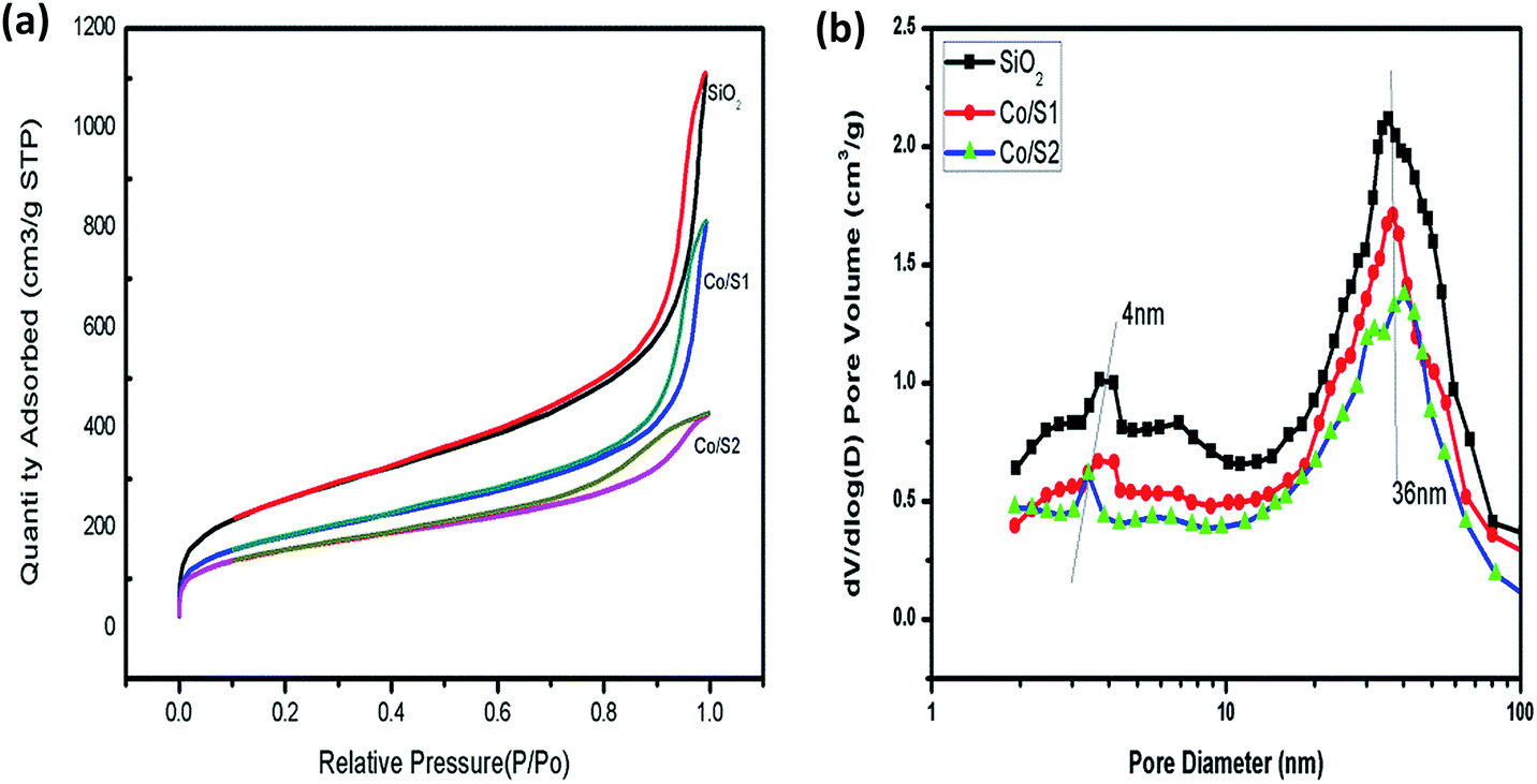 | ||
| Fig. 1 (a) N2 physisorption curves of the samples (b) curves of the pore size distribution of the samples. | ||
The BET surface areas, pore sizes and pore volume data of the supports and the Co/SiO2 catalysts are listed in Table 1. The pore volume of the hierarchical meso–macroporous SiO2 support was as large as 1.729 cm3 g−1; this may be due to the presence of macropores, which can provide channels for rapid molecular transportation. As shown in Table 1, the hierarchical supports and the catalysts all displayed large specific surface areas due to the smaller pores of about 4 nm produced during the sol–gel process, which is beneficial for dispersion of the active components. Compared with the respective supports, the cobalt-loaded catalysts showed lower BET surface areas and pore volumes, which may be due to partial blocking of the pores by cobalt. Catalyst Co/S1 showed a higher BET surface area and pore volume than catalyst Co/S2. This may be due to the severe blocking of the pores by cobalt in catalyst Co/S2, which led to active species aggregation.
| Sample | BET surface area (m2 g−1) | External surface area (m2 g−1) | Vpore (cm3 g−1) | dmesopore (nm) | dmacropore (nm) |
|---|---|---|---|---|---|
| SiO2 | 923.4 | 731.03 | 1.7 | 4.0, 30.0 | 1074.0 |
| Co/S1 | 654.4 | 489.56 | 1.3 | 3.0, 36.8 | 1074.0 |
| Co/S2 | 551.9 | 400.49 | 0.6 | 3.0, 40.0 |
3.2 Phase structures of the samples
Fig. 2 shows the wide-angle XRD patterns of the prepared catalysts. For all the catalysts, the diffraction peaks at 2θ of 31.4°, 36.9°, 44.8°, 59.4°, and 65.2° are related to the crystal planes of the spinel Co3O4 crystalline phase. The average crystallite sizes of the cobalt oxides, calculated from the Scherrer equation at the highest peak (2θ = 36.9°), are listed in Table 2. Catalyst Co/S2 contained larger crystallites than catalyst Co/S1. These results are related to the pore structures of the supports and will be discussed in detail in the following section.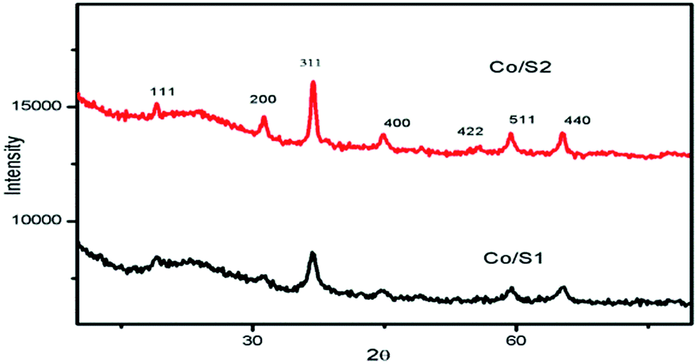 | ||
| Fig. 2 XRD patterns of the catalysts. | ||
3.3 Electron microscopy
Electron microscopy studies were carried out to examine the supports. Fig. 3(a) and (b) show SEM images of the hierarchical SiO2 support (S1) under lower magnification and under higher magnification, respectively. As shown in Fig. 3(a) and (b), S1 exhibited a honeycomb structure. 3-D ordered macrostructures can be seen in S1. Fig. 3(c) and (d) show SEM images of the SiO2 support (S2). As shown in Fig. 3(c) and (d), S2 did not have macropores after destructive grinding; instead, it exhibited dispersed pellets. It should be pointed out that a great deal of effort was required to grind S1 into S2 because S1 has excellent mechanical strength.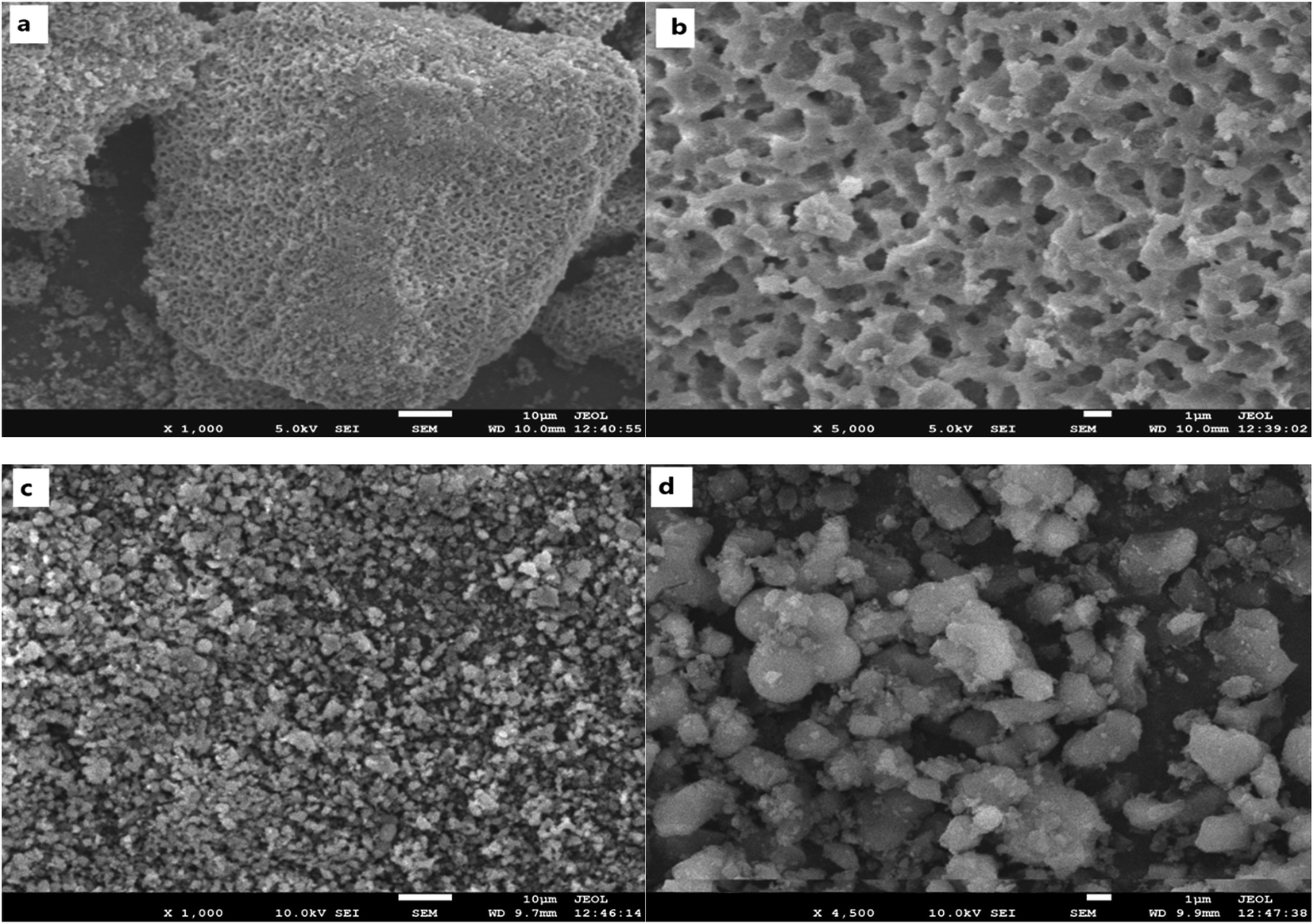 | ||
| Fig. 3 (a) and (b) SEM images of S1; (c) and (d) SEM images of S2. | ||
TEM analysis was conducted to obtain a better understanding of the morphology and distribution of the active species. As shown in Fig. 4, accumulational pores with disordered and worm-like structures could be observed, which are attributed to the larger mesopores (36 nm). Fig. 4(c) and (d) show that in Co/S2, the cobalt aggregation was very severe. However, Fig. 4(a) and (b) show smaller cobalt aggregates in Co/S1, which indicated that Co/S1 had better dispersion. This may indicate the reason why Co/S1 has smaller crystallites. It was very hard to characterize the actual location of the cobalt particles because the mesopores were disordered. We believe some of the cobalt particles are located inside the mesopores; this can be demonstrated by the N2 adsorption–desorption data, shown in Table 1. Compared with the support, the cobalt catalysts showed lower pore volumes, which may be due to the partial blocking of the pores by cobalt. However, as the mesopores were disordered, some of the cobalt particles may have moved outside the mesopores, on the wall of the macropores. Also, this can be demonstrated by the external surface areas of the supports and catalysts. Compared with their respective supports, both cobalt catalysts showed lower external surface areas; this may be because some of the cobalt particles are located outside the mesopores. As mentioned, cobalt particles were located both inside and outside the mesopores; therefore, the confinement effect of the mesopores was not so obvious. Co/S1 may have smaller cobalt crystallite sizes than Co/S2 because S1 has macropores, which may be beneficial to disperse active components.
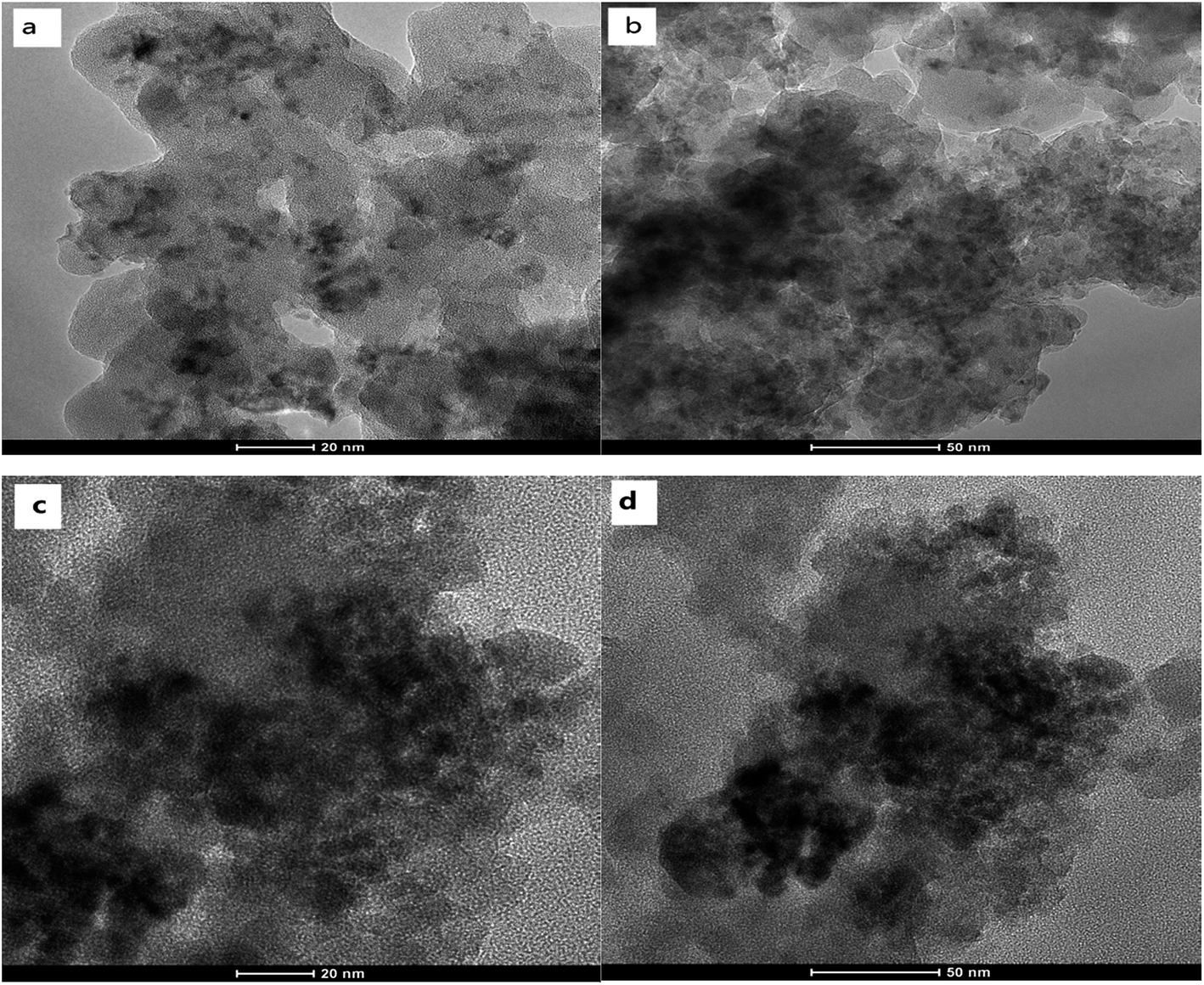 | ||
| Fig. 4 (a) and (b) TEM Images of Co/S1; (c) and (d), TEM Images of Co/S2. | ||
3.4 Reduction behavior of the samples
The reduction behaviors and the interactions between the active phase and the support of each catalyst were examined by H2-TPR, as shown in Fig. 5. Reduction of Co3O4 by hydrogen showed two major regions: first, reduction of Co3O4 to CoO (200 °C to 300 °C); then, reduction of CoO to metallic Co (250 °C to 500 °C).24–26 The broad peaks between 550 °C and 900 °C were related to the reduction of amorphous Co/silica phase. As shown in Fig. 5, Co/S2 had higher reduction intensity than Co/S1, indicating better reducibility. Co/S1 reveals a broad reduction peak in the range of 600 °C to 900 °C, and Co/S2 reveals a very weak reduction peak at 600 °C; this indicates that more cobalt silicate compound was generated in Co/S1 and also shows that Co/S1 had lower reduction. This is consistent with previous reports that small particles are more difficult to reduce than larger particles.27 However, cobalt silicate was not observed by XRD; this may be because the cobalt silicate was amorphous.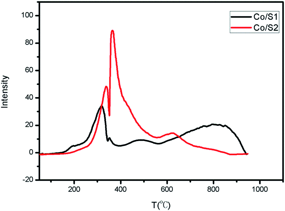 | ||
| Fig. 5 H2-TPR curves of the catalysts. | ||
3.5 Hg intrusion
Hg intrusion was conducted to characterize the macropores. As shown in Fig. 6(a), S1 was well defined; the maximum distribution was centered at 1074 nm, which is consistent with the SEM results. The Hg intrusion and SEM results proved that S1 contains macropores. This indicates that in fact, S1 and Co/S1 have 3-level pore structures, smaller mesopores (about 4 nm), larger mesopores (about 36 nm) and larger macropores (about 1074 nm). Fig. 6(b) shows that there are no macropores in S2. As discussed above, catalyst Co/S2 had larger crystallites than catalyst Co/S1; this may be because the macropores were beneficial to disperse the active components in Co/S1.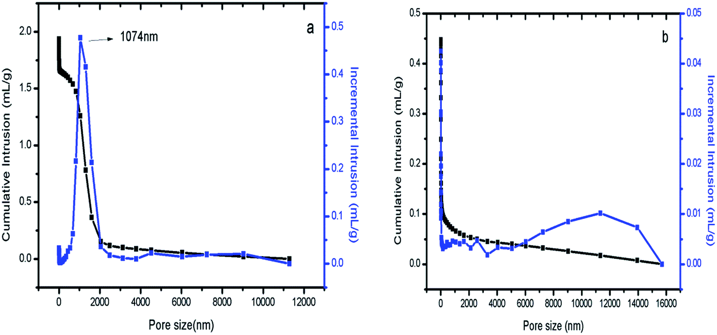 | ||
| Fig. 6 (a) Hg intrusion of S1; (b) Hg intrusion of S2. | ||
3.6 DRIFTS
The diffuse reflectance FTIR spectra of adsorbed CO on the catalysts are shown in Fig. 7. The peaks at 2170 cm−1 and 2130 cm−1 were assigned to gaseous carbon monoxide. The peak at about 2050 cm−1 was assigned to CO adsorbed on cobalt particles in a linear geometry, and the peak at 1935 cm−1 is due to bridged CO adsorbed on cobalt metal.28 It has been reported that large cobalt particles provide large, flat metallic surfaces which favor bridge-type adsorption of CO; small particles provide more edges and corners, favoring CO adsorption in a linear geometry.28 Many researchers consider that bridge-type CO is much more active for the FT reaction than linear-type CO due to a weaker C–O bond that can be more easily dissociated to carbon and oxygen; the latter influences the catalytic activity only slightly.29 As shown in Fig. 7, the peak intensities of the linear-type CO adsorption at 2050 cm−1 on Co/S1 were much stronger than those of Co/S2; this may be because Co/S1 had smaller cobalt particles and better dispersion. Well-dispersed cobalt with small particle sizes can provide more edges and corner sites for CO to adsorb linearly.29 The peak intensities of bridged CO adsorption at about 1935 cm−1 on both the catalysts were very similar, indicating that the two catalysts had similar numbers of active sites available; this suggests the two catalysts had similar activities, although the cobalt particles in Co/S2 were larger than in Co/S1. This may be due to the fact that for Co/S2, the larger particles of cobalt with lower dispersion decreased the number of active sites, resulting in similar bridged CO adsorption to Co/S1. However, the peak at about 1935 cm−1 shifted slightly to a lower wave number (1938 → 1935 cm−1) from Co/S1 to Co/S2, suggesting that the bridged CO adsorbed on Co/S2 more strongly than on Co/S1.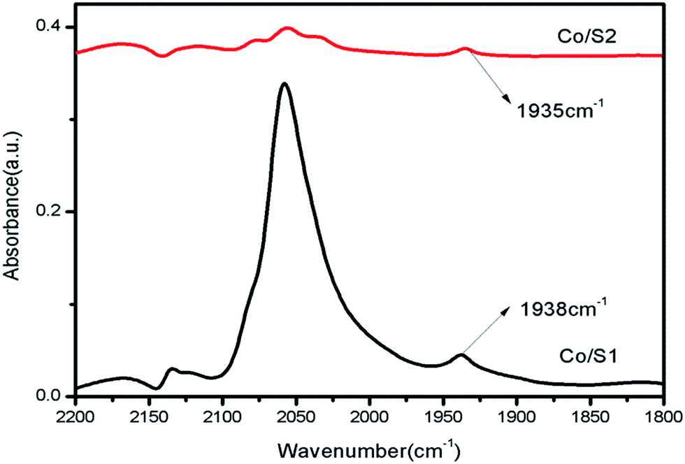 | ||
| Fig. 7 FTIR spectra of CO adsorbed on the catalysts. | ||
3.7 Fischer–Tropsch synthesis reaction behaviour
The FTS is a complex reaction which produces a wide range of hydrocarbon products, including paraffin, olefin, and oxygenated compounds.18 The catalytic results of the FTS reaction are collected in Table 3. It should be noted that all the catalytic data were collected after 24 h under reaction conditions where a steady state for the formation of the product was obtained.| Catalyst | T (°C) | TOF | CO Conv. (%) | Product selectivity [%] | ||||
|---|---|---|---|---|---|---|---|---|
| C1 | C2–4 | C5+ | C5–11 | C12–18 | ||||
| a Reaction conditions: H2/CO = 2, P = 2 Mpa, GHSV = 2.4 L (g−1 h−1), TOS = 24 h. | ||||||||
| Co/S1/10–20 | 220 | 0.026 | 61.48 | 17.01 | 17.11 | 65.88 | 23.80 | 26.57 |
| 240 | 0.033 | 72.59 | 18.38 | 16.87 | 64.75 | 22.72 | 26.09 | |
| Co/S1/60–80 | 220 | 0.020 | 45.41 | 15.91 | 14.83 | 69.26 | 28.87 | 37.83 |
| 240 | 0.035 | 81.53 | 14.03 | 15.27 | 70.70 | 15.59 | 37.29 | |
| Co/S2/10–20 | 220 | 0.018 | 31.54 | 22.84 | 15.05 | 62.11 | 12.83 | 30.37 |
| 240 | 0.031 | 56.37 | 29.17 | 15.01 | 55.82 | 16.59 | 28.75 | |
| Co/S2/60–80 | 220 | 0.025 | 43.54 | 8.24 | 10.48 | 81.28 | 9.84 | 40.95 |
| 240 | 0.048 | 82.95 | 8.88 | 19.93 | 71.19 | 20.00 | 24.30 | |
As we discussed in the introduction, large pellet catalysts exhibit severe internal diffusion limitations; however, small pellet catalysts do not have this problem. Iglesia et al.30 explained that the high methane selectivity and low C5+ selectivity caused by diffusion-inhibited chain growth probability became more severe if the catalyst pellet size was larger than 360 μm or the structure parameter (χ) increased above 200 × 1016 m−1. The structure parameter (χ) can be estimated as follows:
| χ = L2θψ/rp | (1) |
Comparing Co/S1/60–80 with Co/S2/60–80, we found that the two catalysts showed similar CO conversion. It is known that the catalytic activity is affected by the synergy of reducibility and cobalt dispersion.14 Co/S2/60–80 was more readily reduced; however, it did not exhibit higher CO conversion, probably because aggregation of the particles seriously decreased the cobalt dispersion, which was proportional to the number of surface active sites and exposed metal atoms. For Co/S1/60–80, the decreased catalytic activity, which results from the lower reduction degree, may be offset by the enhanced cobalt dispersion. The DRIFTS results showed that the peak intensities of bridged CO adsorption on Co/S1 and Co/S2 were similar, which is in agreement with the FT results. Co/S1/60–80 showed higher methane selectivity and lower C5+ selectivity than Co/S2/60–80; this may be because Co/S1/60–80 (dCo = 6.9 nm) had a smaller cobalt crystal size than Co/S2/60–80 (dCo = 12 nm). For smaller (<10 nm) Co particles, a decrease in FT performance has been reported.31 Using cobalt on carbon nanofiber (CNF) catalysts, tested at both 1 bar and 35 bar, Bezemer et al.31 showed that methane selectivity increased with increasing cobalt crystal size; the methane selectivity become constant when the cobalt particles were larger than 6 nm (1 bar) and 8 nm (35 bar). Also, the larger particles showed higher C5+ selectivity at the same temperature. Although inert supports are very different from porous oxide supports, the same trends were reported by Øyvind Borg and co-workers,32 who used cobalt catalysts supported on Al2O3 (γ-Al2O3 and α-Al2O3). Several suppositions have been used to the explain higher methane selectivity in FT synthesis over small Co particles. First, the high methane selectivity was attributed to sites of weak carbon monoxide adsorption.33 The DRIFTS results showed that the bridged CO adsorbed on Co/S2 shifted slightly to a lower wave number (1938 → 1935 cm−1) compared with Co/S1, indicating that the bridged CO adsorbed on Co/S2 more strongly than on Co/S1. Therefore, the higher methane selectivity of the small Co particles in Co/S1/60-80 obtained with the FT conditions may result from the weak adsorption of Co on the active sites. Second, Breejen et al.34 attributed the higher methane selectivity of small Co particles to their higher hydrogen coverage by Steady-State Isotopic Transient Kinetic Analysis (SSITKA) using cobalt on carbon nanofiber (CNF). Third, Reuel and Bartholomew35 attributed the higher methane selectivity to the presence of stable unreduced oxide phases capable of catalyzing the water–gas shift reaction (CO + H2O → CO2 + H2), thereby increasing the H2/CO ratio at the catalyst surface. Our data do not agree with this interpretation of higher methane selectivity because carbon dioxide was not detected among the reaction products. As discussed above, the higher methane selectivity for smaller cobalt particles of Co/S1/60–80 may be due to the higher coverage of hydrogen and the weak adsorption of CO on the active sites. The TOF was also calculated, as shown in Table 3. Comparing Co/S1/60–80 with Co/S2/60–80, we found that the TOF of Co/S2/60–80 was higher than that of Co/S1/60–80, although their CO conversion was very similar. The difference in TOF may be due to the influence of the cobalt crystalline size. Bezemer et al.31 observed that the TOF gradually increased with cobalt crystalline size in the range of 2.6 to 8 nm and then was constant for larger sizes (8 to 20 nm). Park et al.36 also found that the TOF increased sharply with Co particle size from 4.8 to 9.3 nm and then decreased slightly as the cobalt crystalline size further increased. Our group also obtained the same results using core–shell-structured catalysts; however, the critical size was about 8.7 nm.13 Based on the above discussion, we can attribute the higher TOF of Co/S2/60–80 to its larger cobalt crystalline size (12 nm) compared to that of Co/S1/60–80 (6.9 nm).
Comparing Co/S1/10–20 with Co/S2/10–20, we found that Co/S1/10–20 had higher CO conversion, lower methane selectivity and higher C5+ selectivity than Co/S2/10–20. In addition, we found that the TOF of Co/S1/10–20 was higher than that of Co/S2/10–20, although Co/S2 had a larger cobalt crystalline size than Co/S1. Although the cobalt dispersion, crystal size and reducibility had important effects on FT performance, we prefer to attribute the difference to the existence of macropores in Co/S1/10–20. The effects of internal diffusion limitation existed in both catalysts. However, Co/S1/10–20 contains macropores. The existence of these numerous macropores in Co/S1/10–20 greatly diminished the influence of the internal diffusion limitations due to the large catalyst pellet size, which affects both the catalytic activity and hydrocarbon selectivity. Therefore, this demonstrates that the macropores played an important role in reducing the effects of internal diffusion limitations.
As shown in Table 3, at the same temperature, Co/S1/10–20 and Co/S1/60–80 displayed very similar product selectivities; the selectivity of methane differed by 3.14% and the C5+ selectivity differed by 2.80%. It was found that the C5+ selectivity of Co/S1/10–20 was slightly decreased and the methane selectivity of Co/S1/10–20 was slightly increased compared with those of Co/S1/60–80. This was mainly attributed to the slight diffusion restrictions of the reactants and products, which considerably affected the variation in the hydrocarbon product selectivity in Co/S1/10–20. However, because of the existence of macropores in Co/S1/10–20, the internal diffusion limitations were not as severe. The ASF distributions and α-chain lengthening probabilities were also very similar for Co/S1/10–20 and Co/S1/60–80, as shown in Fig. 8. However, Co/S2/10–20 and Co/S2/60–80 showed very different FT performances; the selectivity for methane differed by 17.44%, and the C5+ selectivity differed by 17.27%. Co/S2/10–20 showed higher methane selectivity, lower CO conversion and lower C5+ selectivity than Co/S2/60–80. In addition, the α value of Co/S2/60–80 (0.88) was much higher than that of Co/S2/10–20, and the ASF distributions were greatly different. As there were serious internal diffusion limitations in Co/S2/10–20, which were more pronounced for CO than for H2 due to different diffusion coefficients, the concentration of CO decreased more, leading to a high H2/CO ratio on the surface of the active sites. Thus, for Co/S2/10–20, the selectivity of methane was very high and the C5+ selectivity was low. However, in Co/S2/60–80, the internal diffusion limitations were not so obvious due to the small pellet size, which contributed to better FT performance. These phenomena can be described by the structural parameters, as stated in eqn (1).30 Because the L value is the exponential term, the effect of this value on the structural parameters is greater than on the other parameters.18 Based on the above discussion, we found that: (1) for FT synthesis, large pellet catalysts showed poor results compared to small pellet catalysts because of the existence of serious internal diffusion limitations; (2) in large pellet catalysts, macropores can help reduce the internal diffusion limitations.
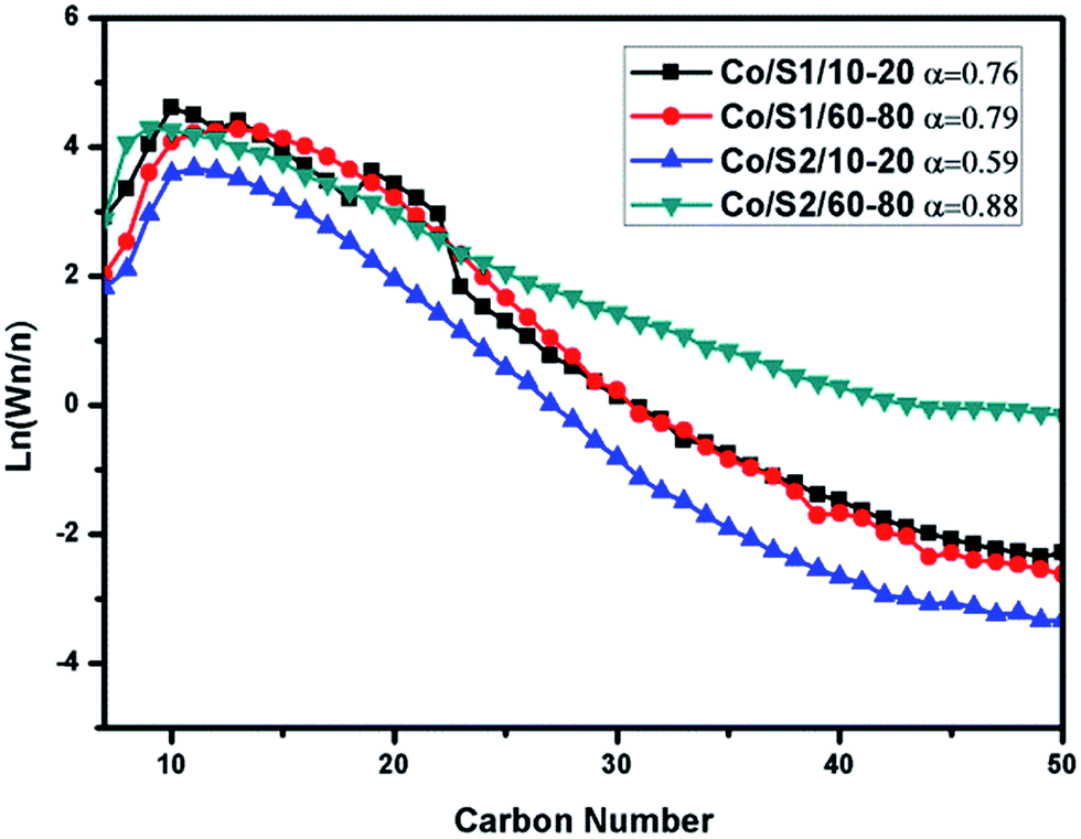 | ||
| Fig. 8 ASF distributions of the catalysts and α-chain lengthening probabilities. Conditions: T = 240 °C, H2/CO = 2, P = 2 Mpa, GHSV = 2.4 L (g−1 h−1), TOS = 24 h. | ||
4 Conclusions
In the present work, hierarchical meso–macroporous silica (S1) and bimodal mesoporous silica (S2) were synthesized by a sol–gel process and used as cobalt supports for Fischer–Tropsch synthesis (FTS). Co/S1 had a 3-level pore structure, and Co/S2 had a bimodal mesoporous structure. It was found that the macroporosities of the catalysts had significant effects on the physico-chemical properties of the cobalt catalysts and also played important roles in the FTS reaction. It was found that when macropores were present, the large pellet catalyst displayed very similar FT performance to the small pellet catalyst. However, in the absence of macropores, the large pellet catalyst displayed much higher methane selectivity than the small pellet catalyst, while CO conversion and C5+ selectivity displayed the opposite trends. Also, the large pellet catalyst with macropores displayed much better FT performance than the large pellet catalyst without macropores. This evidence clearly confirmed the positive effects of abundant macropores on the rapid transport of reactants and products.Acknowledgements
This work was supported by the Natural Science Foundation of China (No. 21203232 and 21273265), and “Strategic Priority Research Program” Demonstration of Key Technologies for Clean and Efficient Utilization of Low-rank Coal, Grant No. XDA07070700.Notes and references
- M. E. Dry, Catal. Today, 1990, 6, 183–206 CrossRef CAS
.
- S. K. Beaumont, Phys. Chem. Chem. Phys., 2014, 16, 5034–5043 RSC
- E. Iglesia, Appl. Catal., A, 1997, 161, 59–78 CrossRef CAS
- C. Ngamcharussrivichai, X. H. Liu, X. H. Li, T. Vitidsant and K. Fujimoto, Fuel, 2007, 86, 50–59 CrossRef CAS
- A. Y. Khodakov, W. Chu and P. Fongarland, Chem. Rev., 2007, 107, 1692–1744 CrossRef CAS PubMed
- A. Zamaniyan, Y. Mortazavi, A. A. Khodadadi and A. N. Pour, J. Energy Chem., 2013, 22, 795–803 CrossRef CAS
- D. Wang, C. B. Chen, J. G. Wang, L. T. Jia, B. Hou and D. B. Li, RSC Adv., 2015, 5, 98900–98903 RSC
- E. Rytter, S. Eri, T. H. Skagseth, D. Schanke, E. Bergene, R. Myrstad and A. Lindvåg, Ind. Eng. Chem. Res., 2007, 46, 9032–9036 CrossRef CAS
- M. F. M. Post, A. C. van't Hoog, J. K. Minderhoud and S. T. Sie, AIChE J., 1989, 35, 1107 CrossRef CAS
- F. Kapteijn, R. M. de Deugd and J. A. Moulijn, Catal. Today, 2005, 105, 350–356 CrossRef CAS
- E. Iglesia, Top. Catal., 1995, 2, 17–27 CrossRef CAS
- H. Becker, R. Güttel and T. Turek, Chem. Ing. Tech., 2014, 86, 4544–4549 Search PubMed
- B. Zeng, B. Hou, L. T. Jia, J. G. Wang, Y. H. Sun and D. B. Li, ChemCatChem, 2013, 5, 3794–3801 CrossRef CAS
- B. Zeng, B. Hou, L. T. Jia, D. B. Li and Y. H. Sun, Catal. Sci. Technol., 2013, 3, 3250–3255 CAS
- X. H. Zhang, H. Q. Su and X. Z. Yang, J. Mol. Catal. A: Chem., 2012, 360, 16–25 CrossRef CAS
- N. Tsubaki, Y. Zhang, S. Sun, H. Mori, Y. Yoneyama, X. H. Li and K. Fujimoto, Catal. Commun., 2001, 2, 311–315 CrossRef CAS
- D. Merino, I. Perez-Miqueo, O. Sanz and M. Montes, Top. Catal., 2016, 59, 207–218 CrossRef CAS
- T. Witoon, M. Chareonpanich and J. Limtrakul, Fuel Process. Technol., 2011, 92, 1498–1505 CrossRef CAS
- H. Q. Yang, Q. Liu, Z. C. Liu, H. X. Gao and Z. K. Xie, Microporous Mesoporous Mater., 2010, 127, 213–218 CrossRef CAS
- R. C. Reul and C. H. Bartholomew, J. Catal., 1984, 85, 63–77 CrossRef
- A. Martínez, C. López, F. Márquez and I. Díaz, J. Catal., 2003, 220, 486–499 CrossRef
- J. G. Wang, H. S. Li, D. B. Li, J. P. Breejen and B. Hou, RSC Adv., 2015, 5, 65358–65364 RSC
- Y. F. Yang, L. T. Jia, Y. Meng, B. Hou, D. B. Li and Y. H. Sun, Catal. Lett., 2012, 142, 195–204 CrossRef CAS
- H. L. Li, S. G. Wang, F. X. Ling and J. L. Li, J. Mol. Catal. A: Chem., 2006, 244, 33–40 CrossRef CAS
- H. L. Li, J. L. Li, H. K. Ni and D. C. Song, Catal. Lett., 2006, 110, 71–76 CrossRef CAS
- Y. C. Liu, J. G. Chen, K. G. Fang, Y. L. Wang and Y. H. Sun, Catal. Commun., 2007, 8, 945–949 CrossRef CAS
- S. L. Soled, E. Iglesia, R. A. Fiato, J. E. Baumgartner, H. Vroman and S. Miseo, Top. Catal., 2003, 26, 1–4 CrossRef
- D. C. Song and J. L. Li, J. Mol. Catal. A: Chem., 2006, 247, 206–212 CrossRef CAS
- D. C. Song, J. L. Li and C. Qin, J. Phys. Chem. C, 2007, 111, 18970–18979 CAS
- E. Iglesia, S. C. Reyes, R. J. Madon and S. L. Soled, Adv. Catal., 1993, 39, 221–302 CAS
- G. L. Bezemer, J. H. Bitter, H. P. C. E. Kuipers, H. Oosterbeek, J. E. Holewijn, X. Xu, F. Kapteijn, A. J. Van Dillen and K. P. De Jong, J. Am. Chem. Soc., 2006, 128, 3956–3964 CrossRef CAS PubMed
- Ø. Borg, P. D. C. Dietzel, A. Spjelkavik, E. Z. Tveten, J. C. Walmsley, S. Diplas, S. Eri, A. Holmen and E. Rytter, J. Catal., 2008, 259, 161–164 CrossRef
- T. J. Fu, J. Lv and L. Zh, Ind. Eng. Chem. Res., 2014, 53, 1342–1350 CrossRef CAS
- J. P. Den Breejen, P. B. Radstake, G. L. Bezemer, J. H. Bitter, V. Frøseth, A. Holmen and K. P. de Jong, J. Am. Chem. Soc., 2009, 131, 7197–7203 CrossRef CAS PubMed
- R. C. Reuel and C. H. Bartholomew, J. Catal., 1984, 85, 78–88 CrossRef CAS
- J.-Y. Park, Y.-J. Lee, P. R. Karandikar, K.-W. Jun, K.-S. Ha and H.-G. Park, Appl. Catal., A, 2012, 411–412, 15–23 CrossRef CAS
| This journal is © The Royal Society of Chemistry 2017 |