 Open Access Article
Intercalation behaviour of magnesium into natural graphite using organic electrolyte systems†
C. Goda,
B. Bitschnaub,
K. Kappera,
C. Lenardta,
M. Schmuck *a,
F. Mautnerb and
S. Kollera
aVARTA Micro Innovation GmbH, Stremayrgasse 9, 8010 Graz, Austria. E-mail: m.schmuck@vartamicroinnovation.com; Fax: +43-316-873-32387; Tel: +43-316-873-32383
bInstitute of Physical and Theoretical Chemistry, Graz University of Technology, Stremayrgasse 9, 8010 Graz, Austria
First published on 2nd March 2017
Abstract
The focus of this study is on the investigation of electrochemical intercalation and deintercalation behaviour of Mg2+ into natural graphite electrodes in organic electrolyte. We used as a conductive salt magnesium bis(trifluoromethylsulfonyl)imide (Mg(TFSI)2) dissolved in N,N-dimethylformamide (DMF) as organic solvent. By utilization of conductivity measurements within a broad temperature range (−20 °C to +60 °C), a conductivity maximum is to be found at a concentration of 0.5 M for all temperatures. Thus, in this study all electrochemical investigations dealing with magnesiation of graphite anodes are made with the electrolyte system 0.5 M Mg(TFSI)2/DMF. In three electrode cells (Swagelok© T-cells) we obtain cathodic and anodic currents, which are highly reversible and last for more than 100 cycles showing a coulombic efficiency above 98%. SEM images reveal a non-destructive intercalation of cationic species into graphite and the formation of a magnesiated graphite intercalation compound is confirmed by ex situ XRD diffraction measurements.
Introduction
The incessant demand of cost-effective and low emission electrification of our society requires alternative strategies to satisfy future energy needs. Such clean and renewable power sources are, for instance, sun, wind or hydropower producing electricity in accordance with meteorological effects that are very fluctuant. For this reason rechargeable batteries are undoubted to be the technology of choice for compensating these instabilities. Merely the combination of green power sources without CO2 production and stationary electrical energy storage devices (EES) equipped with batteries will enable green power's full capacity and a non-intermittent delivery of electricity from its generation to households and end-users, respectively. Among all modern battery systems lithium-ion batteries (LIB) represent the most suitable energy storage system to meet current energy requirements up to today. This can be attributed to their ability to adopt almost every battery size and shape accompanied with a high specific energy- and power density depending only on desired cell design and chemistry (high energy design: 243 W h kg−1, 676 W h l−1 and 250–340 W kg−1).1–3 LIBs can be perfectly tailored for a huge variety of applications in further consequence. However, research of LIBs has to tackle both going to their energy limit and more importantly, challenges such as their needed recharge time, enormous costs and inherent safety issues.4 LIB systems using Li-metal as an anode in order to provide a sufficient energy density, e.g. lithium–sulfur or lithium–air batteries, suffer from intrinsic properties of lithium itself. Unfortunately, lithium deposits on the anode's surface in the shape of needles, well known as dendrites. With subsequent battery cycling and continuous growth of the needle-like crystals severe safety issues may occur because they are able to provoke an internal short circuit by growing from anode to cathode resulting in dangerous fire hazards.5,6 Since then lithium metal as the ultimate metal anode is replaced by carbonaceous materials, which act as host materials for reversible lithium-ion intercalation and deintercalation. However, Li-insertion and distraction mechanism occur at potentials close to that of lithium metal, connoting, too, grave safety issues by lithium plating, e.g. in case of an inadequate cell balancing. On this account alternative technologies beyond lithium-ion batteries are needed if the desire of safe, cheap, well performing and in particular high energy batteries providing even a long cycle life shall be retained. Considering properties such as a rather low reduction potential (−2.36 V vs. SHE), high specific capacity (3380 mA h cm3; two electrons doubling the charge carried per volume), low equivalent weight and moreover, sufficient safety due to a non-dendritic metal deposition, magnesium-ion batteries appear to be competitive to lithium-ion batteries.2Since organic, aprotic electrolyte systems create a passivation layer on the Mg-metal surface preventing a reversible Mg-deposition and dissolution, corrosive electrolytes such as Grignard reagents (RMgX, R = alkyl; X = Br, Cl) have to be used.7,8 Indeed, organometallic Grignard reagents can be reversibly reduced and oxidized but exhibit only a small stability window, that is, decomposition takes place above 1.5 V vs. Mg/Mg2+. Moreover, their feasible application in secondary batteries is limited due to their chemical incompatibility with battery components, e.g. insertion cathode materials. Accordingly, research focuses mainly on further development of these electrolytes with a sufficient oxidative behaviour in order to realize the ambitious goal of a secondary 3 V Mg-battery system which is needed to be competitive to LIB. Such required electrolytes are based on ethereal solutions consisting of magnesium organohaloaluminate salts which were part of Aurbach's pioneering magnesium work already done in the year 2000.5,9 Unfortunately, all these Grignard and Grignard-like electrolytes prone to corrode metals like aluminium, copper, nickel, titanium, etc. The implementation of which is conceivable as current collectors for the positive electrode.10,11 A strategy to circumvent this issue and to achieve the ambitious 3 V goal is the development of intercalation/insertion anode compounds like Ge, Si, Sn or graphite and the replacement of corrosive electrolytes by organic solvents and Mg-conductive salts in combination with common metal oxide cathode materials.12–14 Besides a sufficient oxidative stability organic electrolytes provide (>3.5 V vs. Mg/Mg2+) even the chemical compatibility with the above mentioned current collector materials can be achieved at the same time which would enable the 3 V magnesium-ion battery (MIB) in the end.15–17
Graphite intercalation compounds (GIC) are still the reason behind the success of lithium-ion batteries until today, so lots of effort is still devoted to lithium intercalation into graphite with regard to improve cycle life of LIB, while only little to no information is available for the intercalation behaviour of magnesium into graphite. According to literature it is assumed that Mg-intercalation into graphite is impossible due to strong interfacial reduction reactions especially during the first cycle. Accordingly, organic electrolytes prone to get decomposed, form a passivation layer on the graphite surface and show even solvated intercalation and solvent co-intercalation respectively leading to irreversible exfoliation of graphite itself.18,19 Pontiroli et al., on the contrary, identified the phase Mg2C60 by intercalation of magnesium into fullerenes and could prove the same bonding architecture as the intercalated fulleride Li4C60 exhibits.20 This raises the question of whether the same phase of intercalated graphite compounds can be observed as well. From electrochemical point of view, the theoretical phase of magnesiated graphite would be hypothetically Mg0.5C6 with reference to the full lithiated graphite phase LiC6 both exhibiting the same theoretical capacity of 372 mA h g−1. Giraudet et al. have successfully inserted Mg2+ ions into graphite fluorides by using conventional aprotic electrolytes.21 However it should be mentioned that a structural unstableness for ( ) R30° MgC6 monolayer is predicted by means of density-functional theory (DFT) and ab initio molecular dynamic simulations.22
As a consequence, in this study we want to shed light on the intercalation behaviour of magnesium into graphite showing an apparently non-destructive, reversible magnesiation and de-magnesiation (intercalation and deintercalation) of common natural graphite composite electrodes in combination with common organic, aprotic electrolytes.
Experimental
Graphite based anodes were prepared by dissolution of 7 w% polyvinylidene fluoride (PVDF, Solef® 5130, Solvay) in N-methyl-2-pyrrolidone (NMP, ≥99.8%, Sigma-Aldrich) with subsequent addition of 90 w% natural graphite (Qingdao Nanshu Graphite Co., Ltd., average size 20 μm) and 3 w% carbon black (Super-P, Timcal Ltd.). The resulting slurry was stirred over night to provide a uniform mixture. The slurry is applied onto a copper foil by using the doctor blade technique (Erichsen Multicator 411 with a gap of 150 μm and Erichsen 509 coater). The subsequent steps were removal of NMP in an oven at 70 °C, punching of 12 mm electrode discs and again drying of the obtained electrodes in a glasstube furnish (Büchi) for about 24 hours at 100 °C under vacuum (<10−1 mbar). The electrodes were weighed for determination of their actual active masses per electrode and were dried once again under the same conditions as described before. The final mass loadings of the electrodes were 1.8 to 2.1 mg cm−2.Both electrolyte and electrochemical cell preparations were carried out in an Ar-filled glove box (O2 and H2O < 1 ppm). For the electrolyte preparation magnesium-bis-(trifluoromethylsulfonyl)imide (Mg(TFSI)2, 99.5%, Solvionic) as conductive salt was added to N,N-dimethylformamide (DMF, anhydrous, 99.8%, Sigma Aldrich) in desired concentrations in a range from 0.1 to 1.2 mol l−1 in order to determine a possible conductivity maximum in dependence of the concentration. Mg(TFSI)2 was vacuum dried before use and DMF was dehydrated over molecular sieve (4 Å) for several days. The water content was determined by Karl-Fischer titration technique showing values below 20 ppm. Conductivity measurements of all electrolyte concentrations were performed with a Knick-703 conductometer in a temperature range from −20 °C to +60 °C operating with a four-electrode sensor. Calibration of the cell constant was made with standard solutions before all conductivity measurements (0.1 M NaCl). The dynamic viscosity of all electrolytes was determined within the same temperature range just as the conductivity measurements were done. For the viscosity determination a Stabinger viscometer SVM 3000 from Anton Paar was used.
All electrochemical tests were conducted in a three electrode arrangement in Swagelok-cells with graphite anodes as working electrodes and magnesium metal as counter and reference electrodes (Goodfellow, 99.9%). Prior to cell assembly, both counter- and reference electrodes were polished beforehand in order to remove the oxidized magnesium layer. A polypropylene nonwoven separator (Freudenberg FS 2190) was wetted with 150 μl of non-aqueous electrolyte 0.5 M Mg(TFSI)2 in DMF. Cyclic voltammetry (CV) and constant current cycling (CCC) measurements were recorded on a Bio-Logic MPG-2 battery test station with a scan rate of 0.05 mV s−1 for the CV and different C-rates (0.005C to 0.1C) for up to 100 complete charge/discharge CCC cycles.
The morphology of graphite electrodes before and after electrochemical tests was analysed by Tescan Vega3 scanning electron microscope (SEM) equipped with an Oxford Instruments INCAx-act energy dispersive X-ray (EDX). Cycled electrodes were washed in dry acetone to remove electrolyte residues prior to SEM investigations.
Ex situ X-ray diffraction (XRD) patterns of magnesiated and demagnesiated graphite anodes were recorded on a Bruker D8 powder diffractometer (Cu-Kα radiation, diffraction range of 10 to 80° 2θ, step with 0.02° 2θ, scan rate: 0.1 to 0.2 s per step). In order to exclude any contact of the magnesiated and demagnesiated graphite electrodes with atmospheric oxygen and moisture the anodes were investigated in in-house built ex situ cells equipped with a beryllium window which were assembled in an Ar-filled glove-box. X'Pert High Score Plus (PANalytical) was used for analysis.
Results and discussion
Conductivity and viscosity measurement
Conductivity measurements are made to determine the optimum conductivity of a non-aqueous electrolyte based on Mg(TFSI)2 and DMF in dependence on the conductive salt concentration. The reason for the choice of the electrolyte salt Mg(TFSI)2 is its adequate commercial availability with a reasonable purity and more importantly, it is easy to dissolve in organic, aprotic solvents many magnesium salts do not provide. For instance, magnesium trifluoromethane sulfonate (Mg(Tf)2) exhibits insufficient solubility merely. Even if Mg(TFSI)2 is fairly soluble in several organic solvents DMF is chosen for this study due to its high donor number (Gutmann's DN = 26.5), strong dipole moment and low acceptor number, thus, providing high solubility/solvation abilities and weak interactions with anions.23,24 No solubility problems should arise even at higher salt concentrations in this way. Fig. S1 (ESI†) displays the recorded conductivity of different salt concentrations starting with a 0.1 M concentration stepwise up to 1.2 M Mg(TFSI)2 (0.2 steps) and reveals the existence of a conductivity maximum at a 0.5 M salt concentration in DMF for all temperatures (−20 °C to +60 °C). At +30 °C the conductivity is 16.87 mS cm−1 which is almost three times the conductivity value of MgCl2![[thin space (1/6-em)]](https://www.rsc.org/images/entities/char_2009.gif) :
:![[thin space (1/6-em)]](https://www.rsc.org/images/entities/char_2009.gif) Mg(TFSI)2 (2.5
Mg(TFSI)2 (2.5![[thin space (1/6-em)]](https://www.rsc.org/images/entities/char_2009.gif) :
:![[thin space (1/6-em)]](https://www.rsc.org/images/entities/char_2009.gif) 1 in 1,2 dimethoxyethane) showing the best conductivity among mixtures of magnesium salts (5.80 mS cm−1 at +28 °C).25 Determination of the dynamic viscosity (cf. Fig. S2, ESI†) reveals a non-linear behaviour and more importantly, the freezing of the electrolyte when salt concentrations exceed 0.5 M. With regard to the conductivity maximum and the freezing behaviour it seems reasonable to favour a concentration of 0.5 M Mg(TFSI)2 in DMF for all further electrochemical investigations.
1 in 1,2 dimethoxyethane) showing the best conductivity among mixtures of magnesium salts (5.80 mS cm−1 at +28 °C).25 Determination of the dynamic viscosity (cf. Fig. S2, ESI†) reveals a non-linear behaviour and more importantly, the freezing of the electrolyte when salt concentrations exceed 0.5 M. With regard to the conductivity maximum and the freezing behaviour it seems reasonable to favour a concentration of 0.5 M Mg(TFSI)2 in DMF for all further electrochemical investigations.
Electrochemical experiments
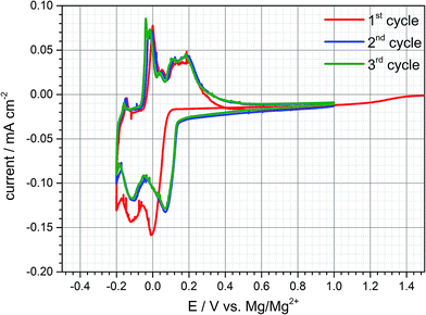
Electrochemical tests are conducted in Swagelok©-half cell configuration to determine the electrochemical behaviour of a natural graphite anode in the DMF based electrolyte containing 0.5 M Mg(TFSI)2. The voltage ranges for individual cyclic voltammetry scans are set to values between −0.5 to +1.0 V vs. Mg/Mg2+ at a scan rate of 0.05 mV s−1. As a result, (cf. Fig. 1) three broad reduction peaks appear below a potential threshold of +0.15 V vs. Mg/Mg2+. In the subsequent anodic sweep three oxidation peaks can be observed between −0.20 and +0.4 V vs. Mg/Mg2+ connoting that all cathodic peaks are reversible. In an analogous manner further eligible electrolytes were characterized with solvents which exhibit a sufficient solubility for Mg(TFSI)2. An intercalation phenomenon comparable to DMF based electrolytes could be observed with dimethylacetamide (DMA) as a solvent (cf. Fig. S4 (ESI†)).Since the inorganic electrolyte salt is dissolved in DMF the only cation species in the electrolyte are magnesium-ions. That implies that both cathodic and anodic reactions suggests a kind of intercalation and deintercalation of Mg2+ between and from the graphene layers respectively. However, the electrochemical reactions exhibit merely a practical capacity during the first cycle of ca. 40 mA h g−1 and the coulombic efficiency reveals an irreversible capacity loss of about 30%. The capacity loss decreases with subsequent cycling indeed, but even in the second and third cycle irreversible capacity can be still detected and reaches values up to 10%. This quite high capacity loss and irreversible capacity, respectively, can be attributed to either continuous electrolyte reduction and/or remaining magnesium-ions within the graphite interlayer.
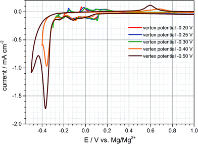
Since the practical capacity only reaches values of around 35–40 mA h g−1 in the first cycles the negative cut-off voltage is adjusted to −0.25 V vs. Mg/Mg2+ trying to enhance practical capacity (cf. Fig. S3 (ESI†)). Once the graphite anode is polarized to this negative potential the third cathodic peak at −0.2 V is much more distinct compared to the previous cycle and the capacity increases to 53 mA h g−1 and 40 mA h g−1 respectively (charge- and discharge capacity). By adjusting the lower vertex potential to even more negative values below −0.25 V vs. Mg/Mg2+ large reduction currents can be observed with little to no oxidation currents in the subsequent anodic sweep during the cyclic voltammogram. As is obvious from Fig. 2, after polarizing the anode to more than even −0.4 V and −0.5 V vs. Mg/Mg2+ large reduction currents appear and the corresponding oxidation peaks shift from around 0 V to +0.7 V. This behaviour can be related to magnesium deposition and electrolyte decomposition, respectively, below −0.3 V and magnesium dissolution at around +0.6 V vs. Mg/Mg2+. The shifted oxidation peak indicates a huge overpotential for the dissolution process which is hardly reversible emphasizing electrolyte decomposition and mainly forming a passivation layer on the graphite anode's surface. The deintercalation process within the range of −0.2 V to 1.0 V vs. Mg/Mg2+ cannot be observed anymore for being inhibited by the passivation layer. Deeper polarization might lead to competitive reactions between magnesium intercalation, electrolyte reduction and magnesium metal deposition. This gives cause for remaining above this vertex potential to prevent these undesired reactions of electrolyte decomposition and passivation of the negative electrode's surface.
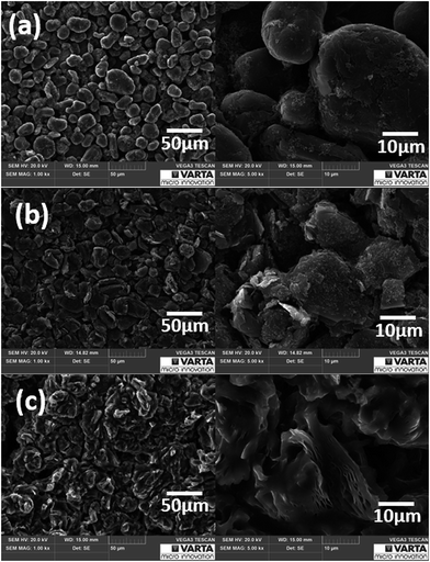
Fig. 3a and b display the morphology of natural graphite anodes before and after electrochemical experiments with 0.5 M Mg(TFSI)2 in DMF respectively. In the SEM images no exfoliation behaviour is detectable as long as the anode is not polarized to more negative potentials than −0.20 V vs. Mg/Mg2+. In comparison to the pristine graphite anode flat flakes of graphite particles with distinct edges are observable after cycling but the entire surface morphology of the graphite electrode is still homogeneous. Since the particles themselves do not become bigger after cycling almost no volume change of the particles is assumed which would be caused by expansion of solvated intercalation/deintercalation processes. The cycled electrode additionally shows particles dispersed on graphite's surface reflecting electrolyte reduction reaction which is common for conventional electrolyte reduction processes.26 Nevertheless, the cycled electrode resembles pristine graphite electrodes and the electrolyte seems to prone to reduction and formation of a “SEI-like interphase layer”.
According to Fig. 3c magnesium metal deposition and massive electrolyte reduction take place forming a passivation layer on the anode's surface which is consistent with the electrochemical results obtained in the cyclic voltammetry in Fig. 2. Graphite particles change their shape because once the graphite anode is polarized below −0.30 V vs. Mg/Mg2+ exfoliation of graphite occurs as well. Obviously, metal deposition and exfoliation seem to be preferred to reversible intercalation/deintercalation reactions at greater polarization then.
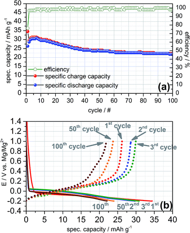
The charge and discharge profiles of the galvanostatic cycles recorded at 0.1C exhibit a similar electrochemical behaviour as obtained in the cyclic voltammetry (cf. Fig. 4a). In the first cycle a practical capacity of 35 mA h g−1 and a rather high irreversible capacity of 25% can be observed while the coulombic efficiency increases with ongoing cycling and reaches values higher than 98% after the 7th cycle. Apparently, the galvanostatic cycling shows a high reversibility of the intercalation and deintercalation of magnesium-ions into and from graphite for more than 100 cycles in the Swagelok© half-cell. Moreover, the charge and discharge plateaus are consistent with the cathodic and anodic peaks shown in the cyclic voltammograms (cf. Fig. 4b). The plateaus of the charging steps are close to +0.15 V vs. Mg/Mg2+ and thus, could be ascribed to magnesium intercalation of Mg2+-ions in between the graphene layers as well. With increasing number of electrochemical cycles the intercalation plateau is continuously shortening and exhibits a practical capacity of 22 mA h g−1 for the 100th cycle finally.
According to literature a reversible, non-destructive intercalation of NR+-cations without solvent co-intercalation into graphite occurs when, e.g. tetrabutylammonium tetrafluoroborate (TBA-BF4) is dissolved in organic solvents.27–30 In order to compare the intercalation behaviour between Mg2+- and TBA+-cations and to deepen the knowledge which intercalation reactions take place we recorded a cyclic voltammogram of a graphite anode vs. Mg metal as counter- and reference electrode using 0.1 M TBA-BF4 in DMF.
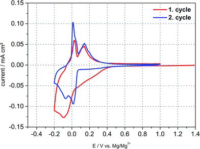
Fig. 5 shows the cyclic voltammetry behaviour and reveals distinct intercalation and deintercalation peaks, which can be attributed to insertion/deinsertion of TBA+-cations in the first cycle. The cathodic and anodic reactions in the second cycle resemble the magnesiation/demagnesiation behaviour of graphite. However, this measurement setup comprises Mg metal as counter electrode, that is, maybe the CV-behaviour originates from Mg2+-cations as well due to oxidation of the counter electrode pretending the intercalation of TBA+-ions. The question arises anyhow what species intercalates into graphite reversibly since no other cation apart from Mg2+ exists in 0.5 M Mg(TFSI)2/DMF electrolyte and in case of the TBA based one both cations may coexist showing an almost exact intercalation behaviour. Nevertheless, the possibility of a solvated co-intercalation still might be applicable.
X-ray diffraction measurements
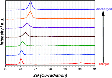
For determination whether solvated intercalation and/or merely magnesiation of graphite takes place ex situ X-ray diffraction is employed.Fig. 6 displays the X-ray diffraction patterns of the intercalated natural graphite electrode prepared by two full cycles of cyclic voltammetry and a subsequent charging step in the 0.5 M Mg(TFSI)2 in DMF electrolyte (half-cycle/charge to −0.2 V vs. Mg/Mg2+ at 0.05 mV s−1). The graphite diffraction peak is clearly observed at a 2θ angle of 26.70°. After the charging step to −0.2 V vs. Mg/Mg2+ this peak is shifted to 2θ angle 26.03° suggesting the widening of the graphene layers and the formation of a graphite interlayer compound of Mg as a consequence. A completely new diffraction peak appears at an angle of 30.05° 2θ as well and is an indication of staging, that suggesting Mg cations in only every nth space between graphene sheets.31 Moreover, this additional peak will disappear during the charging step in case of a solvated intercalation because organic solvent molecules will be decomposed at a certain potential. By contrast, however, its presence can be attributed to the intercalation of magnesium-ions merely. Thus, the intercalated magnesium-ions are not reduced within graphene layer during the charging step. Wagner et al. investigated the XRD behaviour of PC-solvated Li+-ions into graphite leading to the formation of ternary solvated compounds with the formula Lix(PC)yCn.32 In their study an additional diffraction peak at 27.5° 2θ appears as well and the intensity of the original graphite diffraction peak distinctly decreases at the same time. These observed changes are definitely ascribed to co-intercalation of PC and solvated Li+-ions respectively. In case of magnesiated graphite the additional peak at 30.05° 2θ appears indeed, but the intensity of the graphite peak remains more or less the same and shifts to a lower angle only favouring the intercalation of magnesium-ions only. After discharging the graphite electrode the additional peak at 30.05° 2θ disappears completely and the peak at 26.03° 2θ shifts back again to the pristine graphite diffraction peak at 26.70° 2θ with a similar intensity suggesting a non-destructive and highly reversible magnesiation/demagnesiation without irreversible structure damages of the graphite respectively (cf. Fig. 7).
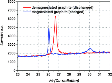 | ||
| Fig. 6 XRD diffraction patterns of magnesiated graphite electrode and the original graphite diffraction peak obtained after discharging the electrode. | ||
The calculation of the obtained diffraction peaks give the characteristic d-value for the pristine graphite lattice constant (d = 3.356 Å). More importantly, the XRD measurement confirms the formation of an intercalated crystalline phase by showing an additional d-value for the charged graphite anode. In order to estimate the degree of intercalation by magnesiation of graphite it might be helpful to compare these d-values with those of lithiated graphite compounds due to very similar ionic radii of both metals (60 pm for Li+ and 65 pm for Mg2+).24 Table 1 summarizes the comparison of dn-values for lithiated graphite taken from literature and the experimentally determined dn-value for magnesiated graphite.33–35 As clearly seen in this table, the repeated graphite interlayer distance of the magnesiated species is quite close to the lithiated one at an intercalation stage corresponding to LixC6 (x = 0.17). The most remarkable fact is, though, that the interlayer distance only widened up a little bit for both intercalated compounds. In case of solvated intercalation it can be concluded that the size of solvated alkali earth metal plays an important role. Magnesium is six-solvated in the organic solvent DMF giving [Mg(DMF)6]2+ and the bond length of magnesium to one of the oxygen atoms of DMF rM–O is 210 pm.36,37 By taking into account that magnesium is six-coordinated, the estimated order for the size of solvated Mg2+-ions will exceed for sure by a factor the bond length of rM–O. The Mg–O distance in DMF with 210 pm indicates that the length of only one solvent molecule to Mg is much bigger than the obtained d-value of the magnesiated graphite compound reflects. Assuming a similar magnesiation GIC with regard to full lithiation of graphite the distance between the graphene layers would be still smaller than one solvated magnesium ion with the formula [Mg(DMF)6]2+. Besenhard et al., for instance, showed for a stage-1-GIC formation a d-value of 1.25 nm resulting from the reduction of (CH3)4NCl in DMSO leading to the composition [(CH3)4·6DMSO]C24.29 According to the work of Santhanam et al., however, TBA+-cations are intercalated into graphite without a solvation sheath in DMSO and show d-values of the intercalated graphite compound of 3.66 Å.30 This distance is very similar to the apparently magnesiated graphite in this study and a solvated intercalation might be excluded from this point of view at the present stage as a consequence. Even if solvated intercalation would be neglected at this point and sheer magnesiation/demagnesiation of graphite are the main electrochemical reactions the reason for the low practical capacity still remains to be investigated. Factors such as graphite particle size, electrolyte conductivity, transference number or transport rate at the interfacial layer electrode–electrolyte and diffusion of magnesium within graphite affect the rate capability. In case that only the graphite particle surface is intercalated due to low magnesium diffusivity within the graphene layers and depending on how deep X-rays penetrate the active material, the original graphite peak at 26.70° 2θ should just be diminished in its intensity. Besides, a shifted peak should arise as well indicating the formed intercalation compound or the widening of the graphene layers at least. However, in this study only the diffraction peak as a whole shifts to a lower angle and a second peak appears additionally, thus is, the total magnesiation of the graphite particle occurs provided that X-rays penetrate the entire graphite particles as mentioned above. The high irreversible capacity of the first electrochemical cycle might be truly attributable to electrolyte decomposition and formation of a “SEI-like interphase layer”, respectively, because neither an additional diffraction peak of magnesium metal nor the disappearance of the 30.05° 2θ diffraction peak during the charging step can be detected.
| Degree of intercalation LixC6/x | Graphite interlayer distance, dn (Li–C)/Å | Graphite interlayer distance, dn (Mg–C)/Å |
|---|---|---|
| 0.00 | 3.358 | 3.356 |
| 0.17 | 13.763 | 13.512 |
| 0.22 | 10.401 | — |
| 0.50 | 7.043 | — |
| 1.00 | 3.703 | — |
Conclusion
We demonstrate a feasible use of natural graphite based electrodes for their utilization as insertion anodes in rechargeable magnesium-ion batteries. Intercalation of magnesium into graphite is highly reversible and shows distinct demagnesiation (deintercalation) peaks in all electrochemical experiments. By applying more negative vertex potentials magnesium deposition and electrolyte decomposition take place, which lead to passivation of the graphite anode surface and suppress intercalation/deintercalation reactions of magnesium as a consequence. Practical capacities are rather low and exhibit only one tenth of the theoretical capacity (372 mA h g−1) with reference to a hypothetically assumed phase with Mg0.5C6 as final stage. SEM images can support this assumption of a reversible, non-destructive co-intercalation of solvated Mg2+-ions since no exfoliation of graphite is detected. XRD investigations reveal the widening up of graphite interlayer distances (d-values) but exclude a solvated intercalation of magnesium and solvent at the same time. Even it is rather uncertain we believe that “SEI-like interphase layer” is formed by electrolyte reduction which does not block Mg2+-ion migration. This hypothesis might be supported by the high irreversible capacity obtained in the first cycles.Taken as a whole, it must be clearly pointed out that the obtained results presented in this study are preliminary and have to be verified for other organic electrolytes consisting of distinct solvents and magnesium salts. Most importantly, there is still uncertainty about the exact reaction mechanisms and whether sheer magnesiation/demagnesiation or co-intercalation of graphite take place. Furthermore, it will be necessary to prove the existence and exact stage of magnesiated graphite intercalation compounds. With this study we want to offer our results, explanations and assumptions, respectively, to other research groups encouraging them to determine dependences of intercalation and deintercalation mechanisms of magnesium into and from graphite and to improve practical capacities. As a consequence, we aim at giving the basis for further development and investigations of insertion anodes in combination with conventional organic electrolytes. This will enable the utilization of common current collectors for already developed cathode materials (MnO2, V2O5, etc.) simultaneously leading to a rechargeable 3.0 V magnesium-ion battery in the end.
References
- D. Linden and T. B. Reddy, Handbook of Batteries, McGraw-Hill, New York, 4th edn, 2011 Search PubMed.
- P. Saha, M. K. Datta, O. I. Velikokhatnyi, A. Manivannan, D. Alman and P. N. Kumta, Prog. Mater. Sci., 2014, 66, 1–86 CrossRef CAS.
- Panasonic, http://industrial.panasonic.com/cdbs/www-data/pdf2/ACI4000/ACI4000CE17.pdf, accessed December 2015.
- MIT Technology Review, M. LaMonica, http://www.technologyreview.com/news/507561/toyota-plugs-away-at-the-next-gen-electric-car-battery/, accessed November 2012.
- K. Xu, Chem. Rev., 2004, 104, 4303–4417 CrossRef CAS PubMed.
- D. Aurbach, Y. Gofer, Z. Lu, A. Schechter, O. Chusid, H. Gizbar, Y. Cohen, V. Ashkenazi, M. Moshkovich, R. Turgeman and E. Levi, J. Power Sources, 2001, 97–98, 28–32 CrossRef CAS.
- Z. Lu, A. Schechter, M. Moshkovich and D. Aurbach, J. Electroanal. Chem., 1999, 203–217 CrossRef.
- J. Muldoon, C. B. Bucur, A. G. Oliver, T. Sugimoto, M. Matsui, H. S. Kim, G. D. Allred, J. Zajicek and Y. Kotani, Energy Environ.Sci., 2012, 5, 5941–5950 CAS.
- D. Aurbach, Z. Lu, A. Schechter, Y. Gofer, H. Gizbar, R. Turgeman, Y. Cohen, M. Moshkovich and E. Levi, Nature, 2000, 407, 724–727 CrossRef CAS PubMed.
- D. Lv, T. Xu, P. Saha, M. K. Datta, M. L. Gordin, A. Manivannan, P. N. Kumta and D. Wang, J. Electrochem. Soc., 2013, 160(2), A351–A355 CrossRef CAS.
- S. Yagi, A. Tanaka, Y. Ichikawa, T. Ichitsubo and E. Matsubara, J. Electrochem. Soc., 2013, 160(3), C83–C88 CrossRef CAS.
- N. Singh, T. S. Arthur, C. Ling, M. Matsui and F. Mizuno, Chem.Commun., 2013, 49, 149–151 RSC.
- O. I. Malyi, T. L. Tan and S. Manzhos, J. Power Sources, 2013, 233, 341–345 CrossRef CAS.
- A. Kitada, Y. Kang, Y. Uchimoto and K. Murase, ECS Trans., 2014, 36, 75–80 CrossRef.
- S. Y. Ha, Y. W. Lee, S. W. Woo, B. Koo, J. S. Kim, J. Cho, K. T. Lee and N. S. Choi, ACS Appl. Mater. Interfaces, 2014, 6, 4063–4073 CAS.
- E. N. Keyzer, H. F. J. Glass, Z. Liu, P. M. Bayley, S. E. Dutton, C. P. Grey and D. S. Wright, J. Am. Chem. Soc., 2016, 138, 8682–8685 CrossRef CAS PubMed.
- M. Zoidl, C. God, P. Handel, R. Fischer, C. Lenardt, M. Schmuck and T. M. Wrodnigg, J. Electrochem. Soc., 2016, 163(10), A2461–A2463 CrossRef CAS.
- M. Kawaguchi and A. Kurasaki, Chem. Commun., 2012, 48, 6897–6899 RSC.
- Y. Maeda and P. Touzain, Electrochim. Acta, 1988, 1493–1497 CrossRef CAS.
- D. Pontiroli, M. Aramini, M. Gaboardi, M. Mazzani, A. Gorreri, M. Riccò, I. Margiolaki and D. Sheptyakov, Carbon, 2013, 51, 143–147 CrossRef CAS.
- J. Giraudet, D. Claves, K. Guerin, M. Dubois, A. Houdayer, F. Masin and A. Hamwi, J. Power Sources, 2007, 173, 592–598 CrossRef CAS.
- C. Cazorla, S. A. Shevlin and Z. Y. Guo, Phys. Rev. B: Condens. Matter Mater. Phys., 2010, 82, 155454 CrossRef.
- M. Katayama, M. Shinoda, K. Ozutsumi, S. Funahashi and Y. Inada, Anal. Sci., 2012, 28, 103–106 CrossRef CAS PubMed.
- D. W. James, R. E. Mayes, W. H. Leong, I. M. Jamie and G. Zhen, Faraday Discuss. Chem. Soc., 1988, 85, 269–281 RSC.
- P. Kurzweil, Advances in Battery Technology for Electric Vehicles, ed. B. Scrosati, J. Garche and W. Tillmetz, Elsevier, 2015, ch. 7, p. 161 Search PubMed.
- S. Komaba, T. Itabashi, B. Kaplan, H. Groult and N. Kumagai, Electrochem. Commun., 2003, 5, 962–966 CrossRef CAS.
- J. O. Besenhard and H. P. Fritz, J. Electroanal. Chem., 1974, 53, 329–333 CrossRef CAS.
- J. O. Besenhard, Carbon, 1976, 14, 111–115 CrossRef CAS.
- J. O. Besenhard, H. Möhwald and J. J. Nickl, Carbon, 1980, 18, 399–405 CrossRef CAS.
- R. Santhanam and M. Noel, J. Power Sources, 1997, 66, 47–54 CrossRef CAS.
- J. A. Seel and J. R. Dahn, J. Power Sources, 2000, 147(3), 892–898 CAS.
- M. R. Wagner, J. H. Albering, K.-C. Moeller, J. O. Besenhard and M. Winter, Electrochem. Commun., 2005, 7, 947–952 CrossRef CAS.
- T. Ohzuku, Y. Iwakoshi and K. Sawai, J. Electrochem. Soc., 1993, 140, 2490–2498 CrossRef CAS.
- H. Kim, J. Hong, G. Yoon, H. Kim, K.-Y. Park, M.-S. Park, W.-S. Yoon and K. Kang, Energy Environ. Sci., 2015, 8, 2963 CAS.
- T. Placke, G. Schmuelling, R. Kloepsch, P. Meister, O. Fromm, P. Hilbig, H.-W. Meyer and M. Winter, Z. Anorg. Allg. Chem., 2014, 640(10), 1996–2006 CrossRef CAS.
- M. Asada, T. Fujimori, K. Fujii, R. Kanzaki, Y. Umebayashi and S. Ishiguro, J. Raman Spectrosc., 2007, 38, 417–426 CrossRef CAS.
- Y. Mizutani, T. Abe, M. Inaba and Z. Ogumi, Synth. Met., 2002, 125, 153–159 CrossRef CAS.
Footnote |
| † Electronic supplementary information (ESI) available: Additional ionic conductivity data, additional viscosity data, additional electrochemical data. See DOI: 10.1039/c6ra28300d |
| This journal is © The Royal Society of Chemistry 2017 |

