 Open Access Article
Creative Commons Attribution 3.0 Unported Licence
In situ construction of Z-scheme g-C3N4/Mg1.1Al0.3Fe0.2O1.7 nanorod heterostructures with high N2 photofixation ability under visible light
Yanjuan Wang,
Wenshi Wei,
Mengyan Li,
Shaozheng Hu *,
Jian Zhang* and
Ruijiang Feng
College of Chemistry, Chemical Engineering, and Environmental Engineering, Liaoning Shihua University, Fushun 113001, Liaoning Province, P. R. China. E-mail: hushaozhenglnpu@163.com
First published on 24th March 2017
Abstract
By tuning the metal ratio, a Z-scheme g-C3N4/MgAlFeO nanorod composite was prepared in situ. The nitrogen photofixation performance under visible light was tested to evaluate the performance of the prepared catalysts. Strong electronic coupling, as evidenced by the XPS, PL and EIS results, exists between the two components in the g-C3N4/Mg1.1Al0.3Fe0.2O1.7 heterojunction photocatalysts, leading to a more effective separation of photogenerated electron–hole pairs and faster interfacial charge transfer, causing the higher activity and stability for N2 photofixation. Neat MgAlFeO shows almost no N2 photofixation activity. However, with the MgAlFeO mass percentage of 23.6%, the as-prepared heterojunction photocatalyst exhibits the highest NH4+ generation rate under visible light, which is 3.5-fold greater than that of individual g-C3N4. A possible Z-scheme mechanism is proposed.
Introduction
Nitrogen is the main ingredient of many important organic compounds in plants. Nitrogen can directly affect the metabolism and growth of all living bodies. Since nitrogen is unusable in its molecular form to most organisms because of its strong nonpolar N![[triple bond, length as m-dash]](https://www.rsc.org/images/entities/char_e002.gif) N covalent triple bond, nitrogen fixation as ammonia is a significant important chemical process in nature. Ammonia is very extensively used in people's daily lives, including as chemical raw materials, fertilizers and refrigerants. However, the biochemical N2 fixation process, which occurs with the help of specialized microorganisms, does not satisfy the increased demand of human beings. During the early 20th century, Haber invented the artificial nitrogen fixation method, the Haber–Bosch process, using hydrogen gas and nitrogen gas as raw materials in the presence of Fe-based catalysts under high pressure and temperature. Both the energy consumption and raw material costs are high for this process. Therefore, artificial nitrogen fixation using cheap raw materials under mild conditions is of considerable significance from the perspectives of cost and environmental protection. With this background, various methods have been developed, including chemical,1,2 electrochemical3,4 and photochemical routes.5,6
N covalent triple bond, nitrogen fixation as ammonia is a significant important chemical process in nature. Ammonia is very extensively used in people's daily lives, including as chemical raw materials, fertilizers and refrigerants. However, the biochemical N2 fixation process, which occurs with the help of specialized microorganisms, does not satisfy the increased demand of human beings. During the early 20th century, Haber invented the artificial nitrogen fixation method, the Haber–Bosch process, using hydrogen gas and nitrogen gas as raw materials in the presence of Fe-based catalysts under high pressure and temperature. Both the energy consumption and raw material costs are high for this process. Therefore, artificial nitrogen fixation using cheap raw materials under mild conditions is of considerable significance from the perspectives of cost and environmental protection. With this background, various methods have been developed, including chemical,1,2 electrochemical3,4 and photochemical routes.5,6
In 1977, the process of N2 reduction to NH3 over Fe doped TiO2 was discovered by Schrauzer et al.5 Since then, nitrogen photofixation technology becomes a hotspot and is considered to be a promising method to replace the traditional Haber–Bosch process. Because of the poor visible light absorption, the traditional Ti-based semiconductor catalysts show unsatisfactory nitrogen fixation ability under visible light.7–9 In recent years, many novel nitrogen-photofixation catalysts are reported successively, including BiOBr (BiOCl), g-C3N4, multi-metal sulfide and FeMoS-Chalcogels.10–16 The details of their finding are shown in Table 1. However, compared with the photocatalytic H2 production, N2 photofixation is more challenging because of the hard formation of high-energy N2 intermediates (N2− or N2H) during the N2 photofixation process.12
| Ref. number | Author | Year | Finding |
|---|---|---|---|
| 7 | Ranjit | 1996 | Noble-metal-loaded TiO2 was used as photocatalyst. A correlation between the M–H bond strength and the yield of ammonia was found |
| 8 | Rusina | 2003 | Fe2Ti2O7 was used as photocatalysts for N2 photofixation |
| 9 | Hoshino | 2001 | Titanium oxide (TiOx) with a conducting polymer material (P3MeT) was used as photocatalyst |
| 10 | Dong | 2015 | They observed that nitrogen vacancies could endow g-C3N4 with the photocatalytic N2 fixation ability |
| 11 | Zhao | 2014 | They used Fe-doped TiO2 with highly exposed (1 0 1) facets to enhance nitrogen photofixation performance |
| 12 | Zhu | 2013 | They demonstrated that illuminated hydrogen-terminated diamond yields facile electron emission into water, thus inducing reduction of N2 to NH3 at ambient temperature and pressure |
| 13 | Hu | 2016 | They found the sulfur vacancies in ternary metal sulfide plays important role on the N2 photofixation ability |
| 14 | Kitano | 2012 | They found that a Ru-loaded [Ca24Al28O64]4+(e−)4 (Ru/C12A7: e−), which has high electron-donating power and chemical stability, works as an efficient catalyst for ammonia synthesis |
| 15 | Banerjee | 2015 | They found that chalcogels containing FeMoS inorganic clusters are capable of photochemically reducing N2 to NH3 |
| 16 | Li | 2016 | They used oxygen vacancies of BiOCl as the catalytic centers to promote the N2 photofixation ability |
g-C3N4, which is shown to function as a semiconductor photocatalyst, has received more and more attentions. This is due to its special physicochemical properties, such as moderate band gap, unique electronic structure and special optical properties. However, as a metal-free organic semiconductor material, its photocatalytic performance is greatly limited by the fast charge recombination and insufficient absorption of visible light.17 Therefore, some g-C3N4 based heterostructured photocatalysts coupling with other semiconductors have been developed in recent years. Metal oxides and sulphides are widely used as this semiconductor to form the heterojunction composites with g-C3N4. In addition to single metal sulfide, some multi-metal sulfides coupled g-C3N4 composites are also reported, including ZnSnCdS/g-C3N4,18 ZnCdS/g-C3N4,19 and ZnMoCdS/g-C3N4.20 However, few studies concerning multi-metal oxide (MMO) coupled g-C3N4 composites are reported.21,22 With the tunable composition, MMO possesses the special optical properties and electronic structure, leading to the formation of tunable band structure. This is beneficial to the energy level matching of two semiconductors, which is significant important to form the heterojunction.23 Chen et al. prepared ZnFe2O4 modified g-C3N4 by a simple one-pot method.21 As a result, the photoinduced electrons and holes in g-C3N4 are efficiently separated by spatial engineering of the photoactive sites, and hence enhanced photocatalytic hydrogen generation activity is obtained. Lan et al. synthesized Zn–In MMO/g-C3N4 hybrid composites by a facile thermal decomposition of Zn–In layered double hydroxide and melamine mixture precursors.22 The higher rhodamine B photocatalytic degradation rate is attributable to the unique heterostructure of the semiconductor coupling system, facilitating efficient transportation and separation of the photogenerated electron–hole pairs and thus the continuous generation of reactive oxygen species. In the best of our knowledge, no studies on the nitrogen photofixation performance over tri-component MMO/g-C3N4 heterojunction photocatalysts have been reported.
In this work, by tuning the metal ratio, Z-scheme g-C3N4/Mg1.1Al0.3Fe0.2O1.7 MMO nanorods composite was prepared in situ. Compared with the ectopic preparation, the heterojunction photocatalysts prepared by this method displayed stronger interaction between g-C3N4 and MMO. The nitrogen photofixation performance under visible light was tested to evaluate the performance of the prepared catalysts. The possible Z-scheme mechanism is proposed.
Experimental
Preparation and characterization
All the chemicals used in this experiment were reagent grade and without further treatment. Mixed salt solutions of Mg(NO3)2·6H2O, Al(NO3)3·6H2O and Fe(NO3)3·9H2O (molar ratio Mg![[thin space (1/6-em)]](https://www.rsc.org/images/entities/char_2009.gif) :
:![[thin space (1/6-em)]](https://www.rsc.org/images/entities/char_2009.gif) Al
Al![[thin space (1/6-em)]](https://www.rsc.org/images/entities/char_2009.gif) :
:![[thin space (1/6-em)]](https://www.rsc.org/images/entities/char_2009.gif) Fe = 10
Fe = 10![[thin space (1/6-em)]](https://www.rsc.org/images/entities/char_2009.gif) :
:![[thin space (1/6-em)]](https://www.rsc.org/images/entities/char_2009.gif) 3
3![[thin space (1/6-em)]](https://www.rsc.org/images/entities/char_2009.gif) :
:![[thin space (1/6-em)]](https://www.rsc.org/images/entities/char_2009.gif) 2) were added into 80 mL deionized water under stirring. Then, desired amount of urea (molar ratio urea/total metal = 1.5) was added. The obtained solution was placed in a stainless autoclave, which has a 100 mL Teflon inner liner. The autoclave was sealed, placed in an oven and maintained at 120 °C for 8 h. The solid was collected by centrifugation, washed with deionized water and dried at 70 °C. The obtained solid was annealed at 520 °C for 2 h (at a rate of 5 °C min−1), and denoted as MgAlFeO. 4 g of dicyandiamide was annealed at 520 °C for 2 h (at a rate of 5 °C min−1). The obtained g-C3N4 catalyst was denoted as CN.
2) were added into 80 mL deionized water under stirring. Then, desired amount of urea (molar ratio urea/total metal = 1.5) was added. The obtained solution was placed in a stainless autoclave, which has a 100 mL Teflon inner liner. The autoclave was sealed, placed in an oven and maintained at 120 °C for 8 h. The solid was collected by centrifugation, washed with deionized water and dried at 70 °C. The obtained solid was annealed at 520 °C for 2 h (at a rate of 5 °C min−1), and denoted as MgAlFeO. 4 g of dicyandiamide was annealed at 520 °C for 2 h (at a rate of 5 °C min−1). The obtained g-C3N4 catalyst was denoted as CN.
0.2, 0.4, 0.8 and 1.6 g of MgAlFeO was added into 20 mL of deionized water respectively and ultrasonicated for 30 min to obtain a suspension. Then, 4 g of dicyandiamide was added under stirring. The suspension was heated and maintained at 60 °C for 10 min to dissolve the dicyandiamide. The suspension was cooled down to room temperature under stirring, during which dicyandiamide was separated out and attached onto MgAlFeO surface. The solid was filtrated, dried at 80 °C and annealed at 520 °C for 2 h (at a rate of 5 °C min−1). The obtained product was denoted as MgAlFeO(1)-CN, MgAlFeO(2)-CN, MgAlFeO(3)-CN and MgAlFeO(4)-CN. MgAlFeO@CN, with the same mass ratio as MgAlFeO(2)-CN, was prepared using ectopic preparation method according to previous work.24 For comparison, the mechanical mixture of CN and MgAlFeO with the same mass ratio as MgAlFeO(2)-CN was also prepared. In order to investigate the reaction mechanism, MMO with other metal ratio (molar ratio Mg![[thin space (1/6-em)]](https://www.rsc.org/images/entities/char_2009.gif) :
:![[thin space (1/6-em)]](https://www.rsc.org/images/entities/char_2009.gif) Al
Al![[thin space (1/6-em)]](https://www.rsc.org/images/entities/char_2009.gif) :
:![[thin space (1/6-em)]](https://www.rsc.org/images/entities/char_2009.gif) Fe = 1
Fe = 1![[thin space (1/6-em)]](https://www.rsc.org/images/entities/char_2009.gif) :
:![[thin space (1/6-em)]](https://www.rsc.org/images/entities/char_2009.gif) 1
1![[thin space (1/6-em)]](https://www.rsc.org/images/entities/char_2009.gif) :
:![[thin space (1/6-em)]](https://www.rsc.org/images/entities/char_2009.gif) 1; 1
1; 1![[thin space (1/6-em)]](https://www.rsc.org/images/entities/char_2009.gif) :
:![[thin space (1/6-em)]](https://www.rsc.org/images/entities/char_2009.gif) 2
2![[thin space (1/6-em)]](https://www.rsc.org/images/entities/char_2009.gif) :
:![[thin space (1/6-em)]](https://www.rsc.org/images/entities/char_2009.gif) 3 and 3
3 and 3![[thin space (1/6-em)]](https://www.rsc.org/images/entities/char_2009.gif) :
:![[thin space (1/6-em)]](https://www.rsc.org/images/entities/char_2009.gif) 2
2![[thin space (1/6-em)]](https://www.rsc.org/images/entities/char_2009.gif) :
:![[thin space (1/6-em)]](https://www.rsc.org/images/entities/char_2009.gif) 1) were prepared and denoted as MAFO, MA2F3O and M3A2FO. The obtained MMO were also used to synthesize heterojunction catalysts following the same procedure as in the synthesis of MgAlFeO(2)-CN. The products were denoted as MAFO-CN, MA2F3O-CN and M3A2FO-CN.
1) were prepared and denoted as MAFO, MA2F3O and M3A2FO. The obtained MMO were also used to synthesize heterojunction catalysts following the same procedure as in the synthesis of MgAlFeO(2)-CN. The products were denoted as MAFO-CN, MA2F3O-CN and M3A2FO-CN.
The XRD patterns of the prepared samples were recorded on a Rigaku D/max-2400 instrument using Cu-Kα radiation (λ = 1.54 Å). The scan rate, step size, voltage and current were 0.05° min−1, 0.01°, 40 kV and 30 mA, respectively. UV-vis spectroscopy was carried out on a JASCO V-550 model UV-vis spectrophotometer using BaSO4 as the reflectance sample. The morphologies of prepared catalyst were observed by using a scanning electron microscope (SEM, JSM 5600LV, JEOL Ltd.). Nitrogen adsorption was measured at −196 °C on a Micromeritics 2010 analyser. All the samples were degassed at 393 K prior to the measurement. The BET surface area (SBET) was calculated based on the adsorption isotherm. ICP was performed on a Perkin-Elmer Optima 3300DV apparatus. The XPS measurements were performed on a Thermo Escalab 250 XPS system with Al Kα radiation as the excitation source. The binding energies were calibrated by referencing the C 1s peak (284.6 eV) to reduce the sample charge effect. The photoluminescence (PL) spectra were measured at room temperature with a fluorospectrophotometer (FP-6300) using a Xe lamp as the excitation source. Electrochemical impedance spectra (EIS) made from these as-made materials were measured via an EIS spectrometer (EC-Lab SP-150, BioLogic Science Instruments) in a three-electrode cell by applying 10 mV alternative signal versus the reference electrode (SCE) over the frequency range of 1 MHz to 100 mHz. The cyclic voltammograms were measured in 0.1 M KCl solution containing 2.5 mM K3[Fe(CN)6]/K4[Fe(CN)6] (1![[thin space (1/6-em)]](https://www.rsc.org/images/entities/char_2009.gif) :
:![[thin space (1/6-em)]](https://www.rsc.org/images/entities/char_2009.gif) 1) as a redox probe with the scanning rate of 20 mV s−1 in the same three electrode cell as EIS measurement.
1) as a redox probe with the scanning rate of 20 mV s−1 in the same three electrode cell as EIS measurement.
Isotopic labeling experiments are carried out as follow. Ar was used to eliminate air and the possible adsorbed ammonia in the reaction system. 15N2 was passed through the reaction mixture for 30 min. After that, the reactor was sealed. Other experiment conditions were the same as those for 14N2 photofixation. The produced 15NH4+ reacts with phenolic and hypochlorite to form 15N labeled indophenol, which was analyzed by LC-MS. The sample for LC-MS analysis was prepared as follows. 0.5 mL of the reaction reacted with 0.1 mL of 1% phenolic solution in 95% ethanol. Then, 0.375 mL of 1% NaClO solution and 0.5 mL of 0.5% sodium nitroprusside solution were added into above solution. MS studies were carried on an Ultimate 3000-TSQ (LCMS-ESI).
Photocatalytic reaction
The nitrogen photofixation property was evaluated according to previous literature.11 The nitrogen photofixation experiments were performed in a double-walled quartz reactor in air. For these experiments, 0.2 g of photocatalyst was added to a 500 mL 0.789 g L−1 ethanol as a hole scavenger.11 The suspension was dispersed using an ultrasonicator for 10 min. During the photoreaction under visible light irradiation, the suspension was exposed to a 250 W high-pressure sodium lamp with main emission in the range of 400 to 800 nm, and N2 was bubbled at 100 mL min−1 through the solution. The UV light portion of the sodium lamp was filtered by a 0.5 M NaNO2 solution. All runs were conducted at ambient pressure and 30 °C. At given time intervals, 5 mL aliquots of the suspension were collected and immediately centrifuged to separate the liquid samples from the solid catalyst. The concentration of ammonia was measured using the Nessler's reagent spectrophotometry method (JB7478-87) with a UV-2450 spectrophotometer (Shimadzu, Japan).11,25Results and discussion
The XRD patterns of as-prepared catalysts are shown in Fig. 1a. Two typical diffraction peaks of g-C3N4 are present in the CN. The peak at 13.1° corresponds to in-plane structural packing motif of tri-s-triazine units, which is indexed as (100) peak. The peak at 27.5° corresponds to interlayer stacking of aromatic segments with distance of 0.324 nm, which is indexed as (002) peak. For MgAlFeO, nine diffraction peaks are observed, which are assigned to MgO, Al2O3 and Fe2O3, respectively.26–28 It is noted that no characteristic diffractions related to g-C3N4 are observed in the MgAlFeO(4)-CN, probably due to the low g-C3N4 content. With the increased CN content, the characteristic diffractions of g-C3N4 can be found clearly. No diffraction peak shift is observed indicating that no metal doping occurs. The UV-vis spectra of the as-prepared heterojunction photocatalysts, as well as those of CN and MgAlFeO, are shown in Fig. 1b. The band gaps are estimated from the tangent lines in the plots of the square root of the Kubelka–Munk function as a function of the photon energy (Fig. 1c).29 CN displays an absorption edge at approximately 452 nm, corresponding to a band gap of 2.74 eV (Table 2). The absorption edge for MgAlFeO is observed at 705 nm, and the corresponding band gap is estimated to be 1.76 eV. For the as-prepared heterojunction photocatalysts, the typical two absorption edges for CN and MgAlFeO are observed, hinting the heterojunction photocatalysts are composed of these two components. The higher MgAlFeO content, the stronger visible light absorption for these heterojunction photocatalysts, corresponding to the color change from light yellow to saffron yellow.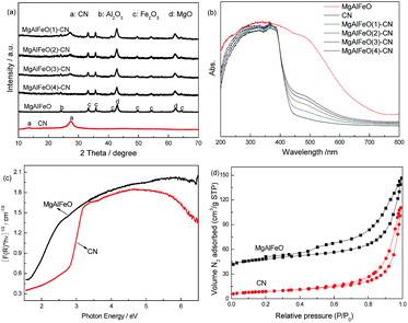 | ||
| Fig. 1 XRD patterns (a) UV-vis spectra (b), plots of the transformed Kubelka–Munk function versus the energy of light (c) and N2 adsorption–desorption isotherms (d) of as-prepared catalysts. | ||
| Sample | CN | MgAlFeO | MAFO | MA2F3O | M3A2FO |
|---|---|---|---|---|---|
| CB position (V) | −1.53 | 0.11 | −0.52 | −0.59 | −0.67 |
| VB position (V) | +1.21 | +1.65 | +1.46 | +1.34 | +1.21 |
| Band gap (eV) | 2.74 | 1.76 | 1.98 | 1.93 | 1.88 |
To characterize the specific surface area of as-prepared catalysts, the nitrogen adsorption and desorption isotherms were measured (Fig. 1d). The isotherm of CN and MgAlFeO are of classical type IV, suggesting the presence of mesopores. The BET specific surface areas (SBET) of CN, MgAlFeO(1)-CN, MgAlFeO(2)-CN, MgAlFeO(3)-CN, MgAlFeO(4)-CN and MgAlFeO are calculated to be 10.5, 12.6, 20.7, 28.9 and 38.6 m2 g−1. The large SBET can promote adsorption, desorption and diffusion of reactants and products, which is favorable to the photocatalytic performance. Table 3 shows the components of as-prepared catalysts obtained by ICP. The C and N contents for CN are 39 wt% and 57 wt%, which is close to the theoretical values. For MgAlFeO, the Mg, Al, Fe and O contents are 33 wt%, 11.5 wt%, 15.5 wt% and 40 wt%, respectively. Thus the actual atomic ratio is Mg1.1Al0.3Fe0.2O1.7. For the as-prepared heterojunction photocatalysts, the MgAlFeO content is 11.7 wt%, 23.6 wt%, 59.3 wt%, and 79.7 wt% for MgAlFeO(1)-CN, MgAlFeO(2)-CN, MgAlFeO(3)-CN and MgAlFeO(4)-CN, respectively.
| Sample | C/wt% | N/wt% | Mg/wt% | Al/wt% | Fe/wt% | O/wt% |
|---|---|---|---|---|---|---|
| CN | 39 | 57 | — | — | — | 4 |
| MgAlFeO | — | — | 34 | 11.5 | 15 | 39.5 |
| MgAlFeO(1)-CN | 35.1 | 53.2 | 3.6 | 1.4 | 1.8 | 4.9 |
| MgAlFeO(2)-CN | 30.6 | 46.8 | 7.0 | 2.6 | 3.4 | 9.6 |
| MgAlFeO(3)-CN | 15.5 | 25.2 | 19.6 | 6.5 | 9.2 | 24 |
| MgAlFeO(4)-CN | 7.9 | 12.4 | 26.3 | 8.5 | 12.3 | 32.6 |
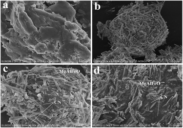
The morphologies of the representative samples were examined using SEM analysis (Fig. 2). Fig. 2a shows that as-prepared CN possesses smooth layer structure. MgAlFeO has a spherical structure assembled by dozens of nanorods (Fig. 2b). In the case of as-prepared heterojunction catalysts, spherical structure MgAlFeO can not be observed. The MgAlFeO nanorods attach on the CN surface to assemble CN/MgAlFeO nanocomposites (Fig. 2c and d). However, some obvious differences between MgAlFeO(2)-CN and MgAlFeO@CN can be observed. For MgAlFeO@CN (Fig. 2c) MgAlFeO nanorods stick to the CN surface. The interaction between MgAlFeO and CN is poor. In the case of MgAlFeO(2)-CN (Fig. 2d), the MgAlFeO nanorods seem to embed into the CN surface. Thus it is deduced that the interaction between MgAlFeO and CN should be stronger than that of MgAlFeO@CN. This stronger interaction can result in the higher interfacial charge transfer rate and more stable CN/MgAlFeO composite structure.
The structure of the as-prepared heterojunction catalyst is investigated by XP spectra. In Mg 2p, Al 2p and Fe 2p regions (Fig. 3a–c), the binding energies for MgAlFeO located at 49.7, 73.8 and 711.3 eV are assigned to the Mg2+, Al3+ and Fe3+ respectively.30–32 For MgAlFeO(2)-CN, the binding energies in Mg 2p, Al 2p and Fe 2p regions exhibit blue-shifts compared with that of MgAlFeO. This electron density change is probably due to the electron transfer from electron-rich g-C3N4 to MgAlFeO. In O 1s region (Fig. 3d), the MgAlFeO displays a single peak at 531.6 eV, which is assigned to the O2− bond to the metal ions. For MgAlFeO(2)-CN, besides this M (metal)–O bond, another peak at 533 eV is observed. As reported by previous literatures, this peak should be assigned to the adsorbed oxygen species.33–35
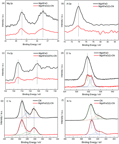 | ||
| Fig. 3 XPS of as prepared catalysts in the region of Mg 2p (a), Al 2p (b), Fe 2p (c), O 1s (d), C 1s (e) and N 1s (f). | ||
In Fig. 3e, the spectra of CN and MgAlFeO(2)-CN in the C 1s region can be fitted with three contributions located at 284.6, 285.8 and 287.8 eV. They are attributed to the C–C bond, which originated from sp2 C atoms bonded to N in an aromatic ring (N–C![[double bond, length as m-dash]](https://www.rsc.org/images/entities/char_e001.gif) N); C
N); C![[double bond, length as m-dash]](https://www.rsc.org/images/entities/char_e001.gif) N or C
N or C![[triple bond, length as m-dash]](https://www.rsc.org/images/entities/char_e002.gif) N, which could be attributed to defect-containing sp2-hybridized carbon atoms present in graphitic domains; and pure graphitic sites in a CN matrix.36 In Fig. 3f, the main N 1s peak of CN located at 398.5 eV can be assigned to sp2-hybridized nitrogen (C
N, which could be attributed to defect-containing sp2-hybridized carbon atoms present in graphitic domains; and pure graphitic sites in a CN matrix.36 In Fig. 3f, the main N 1s peak of CN located at 398.5 eV can be assigned to sp2-hybridized nitrogen (C![[double bond, length as m-dash]](https://www.rsc.org/images/entities/char_e001.gif) N–C), thus confirming the presence of sp2-bonded graphitic carbon nitride. The peak at a higher binding energy of 400.4 eV is attributed to tertiary nitrogen (N–(C)3) groups.37 For MgAlFeO(2)-CN, the remarkable shift to higher binding energy is observed, indicating the decreased electron density of nitrogen atoms. Combined with the phenomenon of binding energy shift in Mg 2p, Al 2p and Fe 2p regions, it is deduced that the strong electronic interaction between the CN and MgAlFeO is formed in MgAlFeO(2)-CN. Besides, no new binding energy is observed for MgAlFeO(2)-CN, indicating that the interaction between CN and MgAlFeO is not chemical bond.
N–C), thus confirming the presence of sp2-bonded graphitic carbon nitride. The peak at a higher binding energy of 400.4 eV is attributed to tertiary nitrogen (N–(C)3) groups.37 For MgAlFeO(2)-CN, the remarkable shift to higher binding energy is observed, indicating the decreased electron density of nitrogen atoms. Combined with the phenomenon of binding energy shift in Mg 2p, Al 2p and Fe 2p regions, it is deduced that the strong electronic interaction between the CN and MgAlFeO is formed in MgAlFeO(2)-CN. Besides, no new binding energy is observed for MgAlFeO(2)-CN, indicating that the interaction between CN and MgAlFeO is not chemical bond.
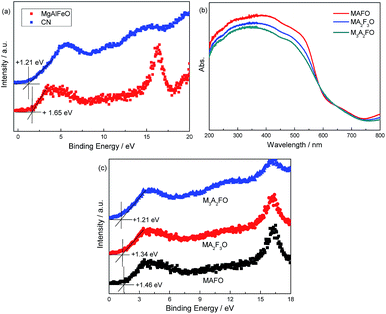
The energy level position of as-prepared catalyst is confirmed by VB XPS. In Fig. 4a, the VB positions of CN and MgAlFeO are +1.21 and +1.65 V (Table 2). It is obtained from the UV-vis results that the band gaps for CN and MgAlFeO are 2.74 and 1.76 eV. Thus the ECB for CN and MgAlFeO is −1.53 and −0.11 V, respectively. Fig. 4b shows the UV-vis spectra of MAFO, MA2F3O and M3A2FO. The absorption edges for MAFO, MA2F3O and M3A2FO are 626, 644 and 659 nm, and the corresponding band gaps are estimated to be 1.98, 1.93 and 1.88 eV, respectively. In Fig. 4c, the VB positions of MAFO, MA2F3O and M3A2FO are +1.46, +1.34 and +1.21 V. Combine with the UV-vis result, the ECB for MAFO, MA2F3O and M3A2FO are −0.52, −0.59 and −0.67 V, respectively. These results indicate that the component of MMO strongly influences the optical property and energy level position of as-prepared materials.
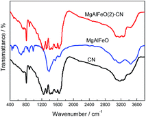
The FT-IR result is provided in Fig. 5. For CN, a series of peaks in the range from 1200 to 1600 cm−1 are attributed to the typical stretching modes of CN heterocycles, while the sharp peak located at 810 cm−1 is assigned to the bending vibration of heptazine rings, which indicating the synthesized g-C3N4 is composed of heptazine units. The broad absorption band around 3200 cm−1 is originated from the stretching vibration of N–H bond, associated with uncondensed amino groups. In the case of MgAlFeO, the peak located at 446 and 480 cm−1 are assigned to the Fe–O stretching and bending vibration modes.38 The peaks at 674 and 1533 cm−1 are attributed to the Mg–O bond.39 The peaks located at 882, 982 and 1372 cm−1 are assigned to the Al–O bond.40 In the case of MgAlFeO(2)-CN, no peak for metal oxide is observed. Theerthagiri et al. prepared α-Fe2O3/g-C3N4 nanocomposites and found the similar phenomenon.38 Besides, no new peak is observed for MgAlFeO(2)-CN, indicating no chemical bond is formed between two components. XPS result confirms this point of view.
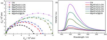
EIS and PL spectra were used to characterize charge-carrier migration and confirm the interfacial charge transfer effect of the as-prepared heterojunction catalysts. As shown in Fig. 6a, after coupling with MgAlFeO, the as-prepared heterojunction catalysts exhibit a decreased arc radius compared to that of CN. In general, the radius of the arc in the EIS spectra reflects the reaction rate on the surface of the electrode.41 The reduced arc radius indicates a diminished resistance of the working electrodes, suggesting a decrease in the solid-state interface layer resistance and the charge transfer resistance across the solid–liquid junction on the surface between CN and MgAlFeO.42,43 MgAlFeO(2)-CN shows the smallest arc radius, indicating that a more effective separation of photogenerated electron–hole pairs and a faster interfacial charge transfer occur. This is reasonable because, with this CN/MgAlFeO mass ratio, CN and MgAlFeO have the approximate SBET (10.5 and 38.6 m2 g−1 for CN and MgAlFeO, Fig. 1d). They can contact with each other as much as possible, leading to the formation of the maximum area of the heterojunction. In Fig. 6b, the PL intensity follows the sequence MgAlFeO(2)-CN < MgAlFeO(1)-CN < MgAlFeO(3)-CN < MgAlFeO(4)-CN < CN. In general, at a lower PL intensity, the separation rate of the photogenerated electron–hole pairs is higher. This confirms the efficient transfer of photoinduced electrons and holes between CN and MgAlFeO in heterojunction catalysts. In addition, both EIS and PL spectra show that the interfacial charge transfer efficiency of MgAlFeO@CN is much lower than that of MgAlFeO(2)-CN. This confirms the stronger interaction between MgAlFeO and CN in MgAlFeO(2)-CN.
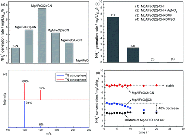
Fig. 7a shows the NH4+ generation rate (r(NH4+)) over the as-prepared catalysts under visible light. The control experiment results indicate that the r(NH4+) can be ignored in the absence of irradiation, N2 or photocatalyst, indicating that nitrogen photofixation occurs via a photocatalytic process. Interestingly, MgAlFeO shows almost no activity though it can absorb visible light, indicating it is not the active component in this reaction system. CN shows the r(NH4+) of 2.1 mg L−1 h−1 gcat−1. The r(NH4+) for as-prepared heterojunction photocatalyst obviously improves compared with CN. MgAlFeO(2)-CN displays the highest r(NH4+), 7.5 mg L−1 h−1 gcat−1, which is approximately 3.5-fold higher than that of CN. AgNO3, as electron scavenger, obviously decreases the nitrogen photofixation ability of MgAlFeO(2)-CN, as shown in Fig. 7b. This hints that the main active species of this nitrogen photofixation reaction is photogenerated electron. The r(NH4+) can be ignorant when using DMF and DMSO as aprotic solvents instead of water (Fig. 7b). This confirms that H2O as the proton source is necessary for the nitrogen photofixation process. In order to further investigate the nitrogen source of NH4+, the N2 photofixation ability of MgAlFeO(2)-CN under 15N isotope-labeled N2 (purity > 98%) was performed. A strong 15N labeled indophenol anion mass spectroscopy signal presents at 199 m/z in LC-MS studies (Fig. 7c). The intensity of this signal is obviously higher than the 14N![[thin space (1/6-em)]](https://www.rsc.org/images/entities/char_2009.gif) :
:![[thin space (1/6-em)]](https://www.rsc.org/images/entities/char_2009.gif) 15N natural abundance ratio, confirming that N2 is the nitrogen source of generated NH4+ in this N2 photofixation process. Fig. 7d compares the photocatalytic N2 fixation stability of as-prepared catalysts. The mixture of MgAlFeO and CN exhibits much lower r(NH4+) than that of MgAlFeO(2)-CN and MgAlFeO@CN which confirms the interfacial charge transfer plays an important role on the photocatalytic performance. MgAlFeO@CN shows the r(NH4+) of 4.2 mg L−1 h−1 gcat−1, lower than that of MgAlFeO(2)-CN. Besides that, MgAlFeO@CN displays a gradually decreased activity, which is approximatively equal to that of mechanical mixture after 20 h reaction. This should be due to the weaker interaction between CN and MgAlFeO for MgAlFeO@CN compared with MgAlFeO(2)-CN. The week interaction not only results in the low interfacial charge transfer rate but also causes the composite split to the mixture of CN and MgAlFeO during the reaction, leading to the poor stability. In the contrary, MgAlFeO(2)-CN shows the stable N2 photofixation ability. The strong interaction causes the stable CN/MgAlFeO composite structure, thus leads to this stable activity. The actual atomic ratio of MgAlFeO is Mg1.1Al0.3Fe0.2O1.7 obtained by ICP. According to the molar ratio, the number of oxygen atoms should be 1.85, indicating the oxygen vacancy should exist. It is also reported by Li et al. that the introduction of oxygen vacancies could activate N2 and promote interfacial electron transfer.25 However, the MgAlFeO shows very poor N2 photofixation ability, probably due to the poor CB driving force. For the as-prepared heterojunction photocatalysts, the actual atomic ratio of multi-metal oxide is hardly obtained because the oxygen also exists in g-C3N4. In order to investigate the influence of oxygen vacancy on the N2 photofixation ability, the MgAlFeO(2)-CN was calcined at 520 °C in O2 atmosphere for 4 h to eliminate the oxygen vacancy. The obtained catalyst shows the similar N2 photofixation ability (7.3 mg L−1 h−1 gcat−1) to that of MgAlFeO(2)-CN (7.5 mg L−1 h−1 gcat−1). Thus it is deduced that the oxygen vacancy should be not responsible for the improved N2 photofixation ability of heterojunction photocatalyst.
15N natural abundance ratio, confirming that N2 is the nitrogen source of generated NH4+ in this N2 photofixation process. Fig. 7d compares the photocatalytic N2 fixation stability of as-prepared catalysts. The mixture of MgAlFeO and CN exhibits much lower r(NH4+) than that of MgAlFeO(2)-CN and MgAlFeO@CN which confirms the interfacial charge transfer plays an important role on the photocatalytic performance. MgAlFeO@CN shows the r(NH4+) of 4.2 mg L−1 h−1 gcat−1, lower than that of MgAlFeO(2)-CN. Besides that, MgAlFeO@CN displays a gradually decreased activity, which is approximatively equal to that of mechanical mixture after 20 h reaction. This should be due to the weaker interaction between CN and MgAlFeO for MgAlFeO@CN compared with MgAlFeO(2)-CN. The week interaction not only results in the low interfacial charge transfer rate but also causes the composite split to the mixture of CN and MgAlFeO during the reaction, leading to the poor stability. In the contrary, MgAlFeO(2)-CN shows the stable N2 photofixation ability. The strong interaction causes the stable CN/MgAlFeO composite structure, thus leads to this stable activity. The actual atomic ratio of MgAlFeO is Mg1.1Al0.3Fe0.2O1.7 obtained by ICP. According to the molar ratio, the number of oxygen atoms should be 1.85, indicating the oxygen vacancy should exist. It is also reported by Li et al. that the introduction of oxygen vacancies could activate N2 and promote interfacial electron transfer.25 However, the MgAlFeO shows very poor N2 photofixation ability, probably due to the poor CB driving force. For the as-prepared heterojunction photocatalysts, the actual atomic ratio of multi-metal oxide is hardly obtained because the oxygen also exists in g-C3N4. In order to investigate the influence of oxygen vacancy on the N2 photofixation ability, the MgAlFeO(2)-CN was calcined at 520 °C in O2 atmosphere for 4 h to eliminate the oxygen vacancy. The obtained catalyst shows the similar N2 photofixation ability (7.3 mg L−1 h−1 gcat−1) to that of MgAlFeO(2)-CN (7.5 mg L−1 h−1 gcat−1). Thus it is deduced that the oxygen vacancy should be not responsible for the improved N2 photofixation ability of heterojunction photocatalyst.
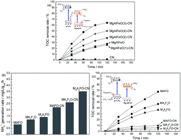
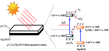
It is reported that the standard redox potential for N2/NH3 is −0.09 V against NHE.9 The reduction potential of CB electrons in CN is more negative than the redox potential for N2/NH3. Thus the CB electrons of CN can reduce the N2 molecule and form the NH3 theoretically. However, MgAlFeO shows almost no N2 photofixation activity though it can absorb visible light. This is probably due to the ECB of MgAlFeO is close to the standard redox potential for N2/NH3, leading to the poor CB driving force. This CB driving force determines the migration rate of photogenerated holes and electrons, causing the ignorant N2 photofixation ability.44 Fig. 8a shows the TOC removal rate of atrazine (a powerful herbicides) in the presence of N2 over as-prepared catalysts. In the contrary of N2 photofixation ability, the TOC removal rate for MgAlFeO is 28%, whereas CN shows almost no activity. The redox potentials for ˙OH/OH− is +1.99 V.45 The VB holes in CN and MgAlFeO are not positive enough to generate ˙OH. Thus the main active species should be holes for the atrazine photodegradation. The obvious activity difference in atrazine photodegradation between CN and MgAlFeO indicates that the VB holes in CN is not positive enough to oxidize atrazine but the VB holes in MgAlFeO can. For the as-prepared heterojunction photocatalysts, the TOC removal rates improve obviously. This hints that, in the as-prepared heterojunction photocatalysts, the photogenerated holes are in the VB of MgAlFeO but not CN. The transfer route of electrons and holes for heterojunction photocatalysts is shown in Fig. 8a inset. Because of the poor CB driving force, the photogenerated electrons in the CB of MgAlFeO can not react with N2 molecule to form NH4+. Consequently, these electrons tend to transfer to the VB of CN and recombine with the photogenerated holes there, leaving photogenerated holes in the VB of MgAlFeO to oxidize atrazine.
Fig. 8b shows the N2 photofixation ability over MAFO, MA2F3O, M3A2FO, MAFO-CN, MA2F3O-CN and M3A2FO-CN. MAFO, MA2F3O and M3A2FO exhibit much higher N2 photofixation ability than that of MgAlFeO (0.2 mg L−1 h−1 gcat−1), which should be due to that the proper energy level position results in the powerful CB driving force. However, the r(NH4+) for MAFO-CN, MA2F3O-CN and M3A2FO-CN are much lower than that of MgAlFeO(2)-CN (7.5 mg L−1 h−1 gcat−1). This hints that their transfer routes of electrons and holes are probably different from each other. In order to confirm this point of view, the TOC removal rates of atrazine in the presence of N2 over MAFO, MA2F3O, M3A2FO, MAFO-CN, MA2F3O-CN and M3A2FO-CN are measured (Fig. 8c). Interestingly, the MAFO-CN, MA2F3O-CN and M3A2FO-CN show much lower TOC removal rate than that of MAFO, MA2F3O and M3A2FO, indicating that the photogenerated holes are in the VB of CN but not MgAlFeO in these heterojunction photocatalysts, as shown in Fig. 8c inset.
According to the results mentioned above, the possible “Z-scheme” mechanism over MgAlFeO(2)-CN is proposed, as shown in Fig. 9. Upon visible-light irradiation, the photogenerated electrons and holes are formed in both CN and MgAlFeO. The electrons in CB of CN react with N2 to form NH4+. Whereas, the N2 photofixation can not be occurred in CB of MgAlFeO because of the poor CB driving force. Consequently, the photogenerated electrons in the CB of MgAlFeO tend to transfer to the VB of CN and recombine with the photogenerated holes there. Therefore, the photogenerated electrons in CB of CN can not back to VB to recombine with the photogenerated holes but react with N2 molecule, leading to the promoted N2 photofixation ability. In the case of MAFO-CN, MA2F3O-CN and M3A2FO-CN system, because of the proper energy level position of MMO, the photogenerated electrons in the CB of MMO can react with N2 molecule but not transfer to VB of CN to recombine with the photogenerated holes there. Thus the “Z-scheme” electrons transfer route is not formed, leading to the lower separation rate and N2 photofixation ability than that of MgAlFeO(2)-CN.
In order to confirm the different electrons transfer route among them, the PL spectra of MgAlFeO(2)-CN, MAFO-CN, MA2F3O-CN and M3A2FO-CN are compared with each other (Fig. 10a). Obviously, the MAFO-CN, MA2F3O-CN and M3A2FO-CN show the comparable PL intensities, which are much higher than that of MgAlFeO(2)-CN. This hints that the interfacial charge transfer efficiency of MgAlFeO(2)-CN is much higher that of MAFO-CN, MA2F3O-CN and M3A2FO-CN, confirming the “Z-scheme” mechanism over MgAlFeO(2)-CN. In addition, since MgO and Al2O3 are non-conductive, the semiconductivity of the mixed oxides should come from Fe2O3. It is known that the coupling of Fe2O3 with g-C3N4 can obviously improve the photocatalytic performance.46–49 Thus the Fe2O3-CN with the same mass ratio with MgAlFeO(2)-CN is prepared for comparison. The PL spectra and N2 photofixation performance of Fe2O3-CN are investigated (Fig. 10b). Obviously, the PL intensity of Fe2O3-CN is much higher than that of MgAlFeO(2)-CN, hinting its lower interfacial charge transfer efficiency. It is known that the ECB and EVB of Fe2O3 are +0.49 and +2.29 eV, respectively.38 Thus the band gap energy and band position of Fe2O3 are obviously different from that of as-prepared MgAlFeO. The ECB of Fe2O3 is much positive than that of MgAlFeO (−0.11 eV), causing the lower driving force from ECB of Fe2O3 to EVB of g-C3N4 than that of MgAlFeO(2)-CN. Thus the interfacial charge transfer efficiency and N2 photofixation performance of Fe2O3-CN are lower than that of MgAlFeO(2)-CN.
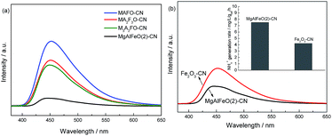 | ||
| Fig. 10 PL spectra of MgAlFeO(2)-CN, MAFO-CN, MA2F3O-CN and M3A2FO-CN (a) and the comparison of PL and N2 photofixation ability of MgAlFeO(2)-CN and Fe2O3-CN (b). | ||
Conclusions
In this work, Z-scheme g-C3N4/MgAlFeO nanorods composite was prepared in situ by tuning the metal ratio. SEM results show that the MgAlFeO nanorods stick but not attach to the CN surface, leading to the strong electronic coupling exists between two components. This strong electronic coupling results in more effective separation of photogenerated electron–hole pairs and faster interfacial charge transfer, causing the higher activity and stability of N2 photofixation. Because of the poor CB driving force, MgAlFeO shows almost no N2 photofixation ability. Thus, the photogenerated electrons can not be consumed in the CB of MgAlFeO. Consequently, these photogenerated electrons tend to transfer to the VB of CN and recombine with the photogenerated holes there, forming the “Z-scheme” interfacial charge transfer mechanism. With the MgAlFeO mass percentage of 23.6%, MgAlFeO(2)-CN exhibits the highest NH4+ generation rate under visible light (7.5 mg L−1 h−1 gcat−1), which is 3.5-fold greater than that of individual CN.Acknowledgements
This work was supported by the Natural Science Foundation of Liaoning Province (2015020590) and Pilot Program of University of Liaoning Innovation and Education Reform.Notes and references
- M. E. Vol’pin, V. B. Shur and E. G. Berkovich, Inorg. Chim. Acta, 1998, 280, 264–274 CrossRef.
- G. J. Leigh, Science, 1998, 279, 506–507 CrossRef CAS.
- E. E. van Tamelen and B. Akermark, J. Am. Chem. Soc., 1968, 90, 4492–4493 CrossRef CAS.
- C. R. Dickson and A. J. Nozik, J. Am. Chem. Soc., 1978, 100, 8007–8009 CrossRef CAS.
- G. N. Schrauzer and T. D. Guth, J. Am. Chem. Soc., 1977, 99, 7189–7193 CrossRef CAS.
- K. T. Ranjit and B. Viswanathan, Indian J. Chem., Sect. A: Inorg., Bio-inorg., Phys., Theor. Anal. Chem., 1996, 35, 443–448 Search PubMed.
- K. T. Ranjit, T. K. Varadarajan and B. Viswanathan, J. Photochem. Photobiol., A, 1996, 96, 181–185 CrossRef CAS.
- O. Rusina, O. Linnik, A. Eremenko and H. Kisch, Chem.–Eur. J., 2003, 9, 561–565 CrossRef CAS PubMed.
- K. Hoshino, Chem.–Eur. J., 2001, 7, 2727–2731 CrossRef CAS.
- G. H. Dong, W. K. Ho and C. Y. Wang, J. Mater. Chem. A., 2015, 3, 23435–23441 CAS.
- W. R. Zhao, J. Zhang, X. Zhu, M. Zhang, J. Tang, M. Tan and Y. Wang, Appl. Catal., B, 2014, 144, 468–477 CrossRef CAS.
- D. Zhu, L. Zhang, R. E. Ruther and R. J. Hamers, Nat. Mater., 2013, 12, 836–841 CrossRef CAS PubMed.
- S. Z. Hu, X. Chen, Q. Li, Y. F. Zhao and W. Mao, Catal. Sci. Technol., 2016, 6, 5884–5890 CAS.
- M. Kitano, Y. Inoue, Y. Yamazaki, F. Hayashi, S. Kanbara, S. Matsuishi, T. Yokoyama, S. W. Kim, M. Hara and H. Hosono, Nat. Chem., 2012, 4, 934–940 CrossRef CAS PubMed.
- A. Banerjee, B. D. Yuhas, E. A. Margulies, Y. B. Zhang, Y. Shim, M. R. Wasielewski and M. G. Kanatzidis, J. Am. Chem. Soc., 2015, 137, 2030–2034 CrossRef CAS PubMed.
- H. Li, J. Shang, J. G. Shi, K. Zhao and L. Z. Zhang, Nanoscale, 2016, 8, 1986–1993 RSC.
- Z. H. Chen, P. Sun, B. Fan, Q. Liu, Z. G. Zhang and X. M. Fang, Appl. Catal., B, 2015, 10–16, 170–171 Search PubMed.
- S. Z. Hu, Y. M. Li, F. Y. Li, Z. P. Fan, H. F. Ma, W. Li and X. X. Kang, ACS Sustainable Chem. Eng., 2016, 4, 2269–2278 CrossRef CAS.
- Q. Nie, Q. Yuan and Q. Wang, J. Mater. Sci., 2004, 39, 5611–5612 CrossRef CAS.
- X. L. Fu, X. X. Wang, Z. X. Chen, Z. Z. Zhang, Z. H. Li, D. Y. C. Leung, L. Wu and X. Z. Fu, Appl. Catal., B, 2010, 95, 393–399 CrossRef CAS.
- J. Chen, S. H. Shen, P. H. Guo, P. Wu and L. J. Guo, J. Mater. Chem. A, 2014, 2, 4605–4612 CAS.
- M. Lan, G. L. Fan, L. Yang and F. Li, RSC Adv., 2015, 5, 5725–5734 RSC.
- S. Z. Hu, F. Y. Li, Z. P. Fan, F. Wang, Y. F. Zhao and Z. B. Lv, Dalton Trans., 2015, 44, 1084 RSC.
- S. Nayak, L. Mohapatra and K. Parida, J. Mater. Chem. A, 2015, 3, 18622–18635 CAS.
- H. Li, J. Shang, Z. H. Ai and L. Z. Zhang, J. Am. Chem. Soc., 2015, 137, 6393–6399 CrossRef CAS PubMed.
- J. Choi, S. H. Zhang and J. M. Hill, Catal. Sci. Technol., 2012, 2, 179–186 CAS.
- Y. D. Ding, G. Song, X. Zhu, R. Chen and Q. Liao, RSC Adv., 2015, 5, 30929–30935 RSC.
- Z. H. Gu, K. Z. Li, S. Qing, X. Zhu, Y. G. Wei, Y. T. Li and H. Wang, RSC Adv., 2014, 4, 47191–47199 RSC.
- Y. I. Kim, S. J. Atherton, E. S. Brigham and T. E. Mallouk, J. Phys. Chem., 1993, 97, 11802–11810 CrossRef CAS.
- H. P. R. Kannapu, C. K. P. Neeli, K. S. R. Rao, V. N. Kalevaru, A. Martin and D. R. Burri, Catal. Sci. Technol., 2016, 6, 5494–5503 CAS.
- S. W. Lee, J. Heo and R. G. Gordon, Nanoscale, 2013, 5, 8940–8944 RSC.
- X. S. Zhou, B. Jin, R. Q. Chen, F. Peng and Y. P. Fang, Mater. Res. Bull., 2013, 48, 1447–1452 CrossRef CAS.
- H. Xu, J. Yan, X. J. She, L. Xu, J. X. Xia, Y. G. Xu, Y. H. Song, L. Y. Huang and H. M. Li, Nanoscale, 2014, 6, 1406–1415 RSC.
- K. X. Li, L. S. Yan, Z. X. Zeng, S. L. Luo, X. B. Luo, X. M. Liu, H. Q. Guo and Y. H. Guo, Appl. Catal., B, 2014, 156–157, 141–152 CrossRef CAS.
- P. Niu, Y. Q. Yang, J. C. Yu, G. Liu and H. M. Cheng, Chem. Commun., 2014, 50, 10837–10840 RSC.
- L. Ge and C. Han, Appl. Catal., B, 2012, 117–118, 268–274 CrossRef CAS.
- Y. W. Zhang, J. H. Liu, G. Wu and W. Chen, Nanoscale, 2012, 4, 5300–5303 RSC.
- J. Theerthagiri, R. A. Senthil, A. Priya, J. Madhavan, R. J. V. Michael and M. Ashokkumar, RSC Adv., 2014, 4, 38222–38229 RSC.
- X. X. Huang, Y. Men, J. G. Wang, W. An and Y. Q. Wang, Catal. Sci. Technol., 2017, 7, 168–180 CAS.
- J. Gangwar, B. K. Gupta, S. K. Tripathi and A. K. Srivastava, Nanoscale, 2015, 7, 13313–13344 RSC.
- Y. Xu, H. Xu, L. Wang, J. Yan, H. Li, Y. Song, L. Huang and G. Cai, Dalton Trans., 2013, 42, 7604–7613 RSC.
- B. L. He, B. Dong and H. L. Li, Electrochem. Commun., 2007, 9, 425–430 CrossRef CAS.
- Q. W. Huang, S. Q. Tian, D. W. Zeng, X. X. Wang, W. L. Song, Y. Y. Li, W. Xiao and C. S. Xie, ACS Catal., 2013, 3, 1477–1485 CrossRef CAS.
- S. Z. Hu, L. Ma, F. Y. Li, Z. P. Fan, Q. Wang, J. Bai, X. X. Kang and G. Wu, RSC Adv., 2015, 5, 90750–90756 RSC.
- S. Z. Hu, L. Ma, J. G. You, F. Y. Li, Z. P. Fan, G. Lu, D. Liu and J. Z. Gui, Appl. Surf. Sci., 2014, 311, 164–171 CrossRef CAS.
- K. C. Christoforidis, T. Montini, E. Bontempi, S. Zafeiratos, J. J. D. Jaén and P. Fornasiero, Appl. Catal., B, 2016, 187, 171–180 CrossRef CAS.
- Y. Liu, F. Y. Su, Y. X. Yu and W. D. Zhang, Int. J. Hydrogen Energy, 2016, 41, 7270–7279 CrossRef CAS.
- X. Liu, A. L. Jin, Y. S. Jia, J. Z. Jiang, N. Hu and X. S. Chen, RSC Adv., 2015, 5, 92033–92041 RSC.
- Y. Liu, Y. X. Yu and W. D. Zhang, Int. J. Hydrogen Energy, 2014, 39, 9105–9113 CrossRef CAS.
| This journal is © The Royal Society of Chemistry 2017 |

