 Open Access Article
Ferrimagnetic half-metallic properties of Cr/Fe δ doped MoS2 monolayer
M. D. Xiea,
C. G. Tan*a,
Pan Zhou a,
J. G. Linb and
L. Z. Sun
 *b
*b
aKey Laboratory of Low-Dimensional Materials and Application Technology, School of Material Sciences and Engineering, Xiangtan University, Xiangtan 411105, China. E-mail: gctan@xtu.edu.cn
bHunan Provincial Key Laboratory of Thin Film Materials and Devices, School of Material Sciences and Engineering, Xiangtan University, Xiangtan 411105, China. E-mail: lzsun@xtu.edu.cn
First published on 6th April 2017
Abstract
Using first-principles calculations, we found that Cr/Fe δ-type doping is an effective approach to modulate the electronic and magnetic properties of monolayer MoS2. Distinguished from ferromagnetic half-metallic Fe δ-type doped MoS2, Cr and Fe alternately δ-type codoped MoS2 presents half-metallic ferrimagnetism. The 3d orbitals of Cr and Fe strongly couple with the p states of their nearest neighbor S, and virtual hopping between them follows the GKA rules, thus the antiferromagnetic superexchange interaction between Cr and Fe produces the ferrimagnetic nature of the system. Our results indicated that the 3d δ-type doping in monolayer MoS2 provides an effective approach to produce a one dimensional spin-polarized transport channel.
1 Introduction
Since de Groot1 proposed the concept of half-metallic ferromagnets (HMFs) from the band structure of NiMnSb, HMFs have been a hot research topic during the last few decades due to their potential applications in spintronics. Half-metal materials, with 100% spin-polarized2 conduction electrons at the Fermi level, are a class of special magnetic materials that can be used as magnetic layers in magnetic tunnel junctions to obtain prodigious magnetoresistance.3 Lately, lots of materials have been predicted theoretically to exhibit this particular behavior, such as rutile CrO24 and mixed-valence perovskite Mn-doped GaAs.5Although the HMF shows great potential in spintronics, the magnetic domains and stray field in the system due to its ferromagnetic (FM) nature will inevitably restrict the generation of a spin-polarized current. van Leuken and de Groot6 proposed that this half-metallic nature can be achieved in antiferromagnets (HMAs) or ferrimagnets (HMFi’s), which will overcome the drawbacks of HMFs due to their zero or smaller magnetization. HMAs, with half-metallic characteristics but without any net magnetization, have been theoretically predicted in V7MnFe8Sb7In alloys,6 perovskite oxides,7,8 Mott insulator NiO,9 monolayer superlattices,10 and diluted magnetic semiconductors.11 All of them show potential applications in novel spin-polarized STM tips,6 new spin injection devices, and single spin superconductivity.7 Besides HMAs, HMFi’s also aroused a lot of concerns due to their lower total magnetic moments in comparison to those of HMFs. van Leuken and de Groot6 theoretically proposed that FeMnSb is half-metallic with a net moment of only 2 μB due to the antiparallel spin moments between Fe and Mn behaving as HMFi’s. HMFi’s create smaller external magnetic fields and this results in smaller energy losses in comparison to HMFs. In addition, HMFi’s provide the prototypic template for designing HMAs. For example, starting from Mn2VAl and Mn2VSi Heusler alloys which are well known HMFi’s, Galanakis et al.12 obtained a desirable HMA by substituting Co and Fe for Mn.
Traditionally, HMAs and HMFi’s were realized in complex crystal structures such as perovskite cuprates. The complex structures may suppress their magnetic properties owing to the lattice distortions in the systems.3 In comparison with the materials mentioned above, two dimensional (2D) materials, especially the 2D materials with large band gaps, are more suitable for spintronics due to their simple structures and easily controllable magnetic properties.13 In our previous work,14,15 half-semiconductor antiferromagnets with vanishing net magnetization were proposed in 2D h-BN, GaN, AlN, and Janus MXenes, paving the way for HMAs in 2D materials. One of the most recently obtained 2D materials, MoS2, with an S–Mo–S sandwich structure, is a direct band gap semiconductor with a band gap of 1.8 eV,16 which is potentially useful in transistors,17 phototransistors,18 gas transducers,19 lithium and sodium batteries, and solar cells.20–22 Experimentally, mono- and multi-layer MoS2 have been successfully fabricated through various methods including chemical vapor deposition,23 a liquid exfoliation method,24 mechanical exfoliation,25 and sulfurization of a pre-deposited transition metal or transition metal oxide.26,27 The pristine MoS2 analogous to graphene is a nonmagnetic material. To promote its applications in spintronics, methods including cutting the material into zigzag MoS2 nanoribbons,28 transitional metal (TM) adsorption,29,30 and TM doping31–34 were used. Among them, TM substitutional doping is one of the most simple and effective techniques to modulate the electronic and magnetic properties of MoS2. Substitutional doping of various TM dopants at the S or Mo sites has been successfully used to modulate the magnetic and electronic structure of the MoS2 monolayer.31–34 In comparison with TM atom substitutional doping at the S site, the absolute value of the binding energy (Eb) indicates that TM doping at the Mo site is more stable.35 However, substitutionally doping the TM atom at the Mo site only induces small magnetic moments, and the material still remains as a semiconductor with a narrower band gap.36 Previous studies have indicated that a total magnetic moment of 2 μB is observed for Fe doping, but doping with Cr shows a Jahn–Teller distortion and consequently no magnetism.36 Such results derive from single TM doping without considering the coupling between the TM dopants. The question is how the TM coupling influences the magnetic and electronic properties of the TM doped systems. Such an issue deserves more attention.
In this work, taking Cr/Fe, Cr, and Fe δ-type doped monolayer MoS2 including four different configurations as examples, we investigate the influence of TM coupling on the magnetic and electronic properties of Cr/Fe δ doped monolayer MoS2. We find that the Fe δ-type doped monolayer MoS2 behaves as a HMF with a magnetic moment of 4 μB for each Fe. The results indicate that the coupling between Fe produces the high spin state of Fe in the system. As for the Cr δ-type doped system, the Cr anti-ferromagnets couple with each other, so the system behaves as a non-magnetic semiconductor. The Cr and Fe δ-type codoped material with a CrCrFeFe-chain-MoS2 configuration is a metal. The neighboring CrCr, FeFe, and FeCr all show anti-ferromagnetic coupling, so these produced systems only show slight magnetic moments, while the system with an FeCrFeCr-chain-MoS2 configuration behaves as a HMFi’ with 100% spin-polarization even though the neighboring Fe and Cr show anti-ferromagnetic coupling. The system shows 2 μB magnetic moments per unit cell and the metallic characteristics derive from the spin-up channel contributed to by Fe and its neighboring S and Mo atoms. The anti-ferromagnetic coupling in the FeCrFeCr-chain-MoS2 configuration follows the superexchange of the GKA rules. The results in the present work indicate that the δ-type doping in monolayer MoS2 is an effective method to produce a one-dimensional spin-polarized transport channel.
2 Models and computational methods
Our calculations were performed using the spin-polarized density-functional theory (DFT),37,38 as implemented in the Vienna ab initio simulation package (VASP).39,40 The first-principles method adopted in our present work is suitable to study the electronic and magnetic properties of nano-magnetic materials, which has been proven by lots of previous reports.41,42 Projector augmented wave (PAW)43,44 potentials were used to describe the electron–ion interactions and the generalized gradient approximation (GGA) of Perdew, Burke, and Ernzerhof (PBE)45 was adopted for electron exchange and correlation interactions. The plane-wave kinetic energy cutoff of 500 eV was employed, which is sufficiently large for our systems. For single Cr or Fe doped monolayer MoS2, we adopted a 4 × 4 supercell containing 32 S, 1 Cr (or Fe) and 15 Mo. A gamma-centered 5 × 5 × 1 k-mesh was applied for relaxation calculations and a 7 × 7 × 1 k-sampling for static calculations. To investigate the δ-type doping of Cr and Fe in MoS2, a large periodic supercell should be used in the calculation. We found that a 7 × 4 supercell is large enough by testing different supercell sizes. In the supercell, the Cr/Fe magnetic chain is along the y-axis, and the x-axis is greater than 19 Å to avoid interactions between the two Cr/Fe magnetic chains in the neighboring images. To avoid interaction between adjacent images, the vacuum region perpendicular to the sheet was set to 15 Å. The first Brillouin zone (BZ) was sampled by adopting 1 × 5 × 1 and 3 × 7 × 1 gamma-centered Monkhorst–Pack grids for geometry relaxation and electronic structure calculations, respectively. The criteria for the energy and atomic force convergence were set to 10−6 eV per unit cell and 0.01 eV Å−1, respectively.The electronic properties of the TM δ-type doped monolayer MoS2 are sensitive to the treatment of the local Coulomb interactions U of the TM d orbital due to its strong localization. Therefore, DFT+U46 is an essential approach to accurately investigate the electronic structures of Cr/Fe, Cr, and Fe δ-type doped monolayer MoS2. In the present work, we perform GGA+U calculations and apply Ueff = 4.0 eV to the Cr and Fe atoms. We also test Ueff = 3.0 eV and Ueff = 5.0 eV, with the results revealing that there is no significant impact on the electric and magnetic properties upon changing the Ueff value. We tested the results of small size MoS2 with 3d transition metal doping based on functional HSE06, which gave similar magnetic properties (the main point of our present work) with those based on PBE+U. Considering the time consuming nature of HSE06, we adopted PBE+U in the present work.
3 Results and discussions
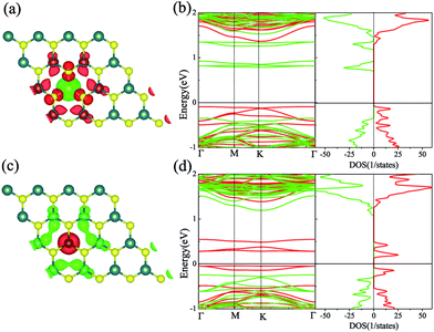
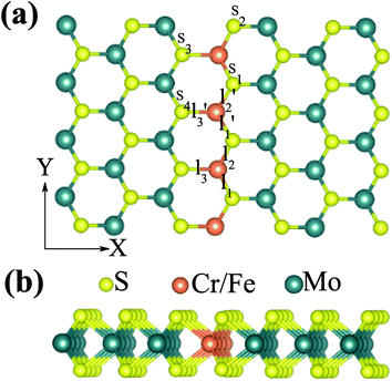
We firstly studied the electronic and magnetic properties of single Cr/Fe doped MoS2 (denoted as Cr–MoS2 and Fe–MoS2, respectively). The structure, spin charge density (SCD) derived from the difference in the charge density between the spin-up and spin-down channels, band structures, and density of states (DOS) of single Cr/Fe doped MoS2 are shown in Fig. 1. As shown in Fig. 1(b), there is obvious asymmetry between the spin-up and spin-down channels for Cr doped MoS2 around the Fermi level, which indicates that Cr doping can induce spin-polarized states. However, although the Cr atom shows a −2.689 μB local magnetic moment, the total magnetic moment of the system is 0 μB. The SCD as shown in Fig. 1(a) indicates that the antiferromagnetic Cr couples with its neighboring S/Mo atoms. Each of its six nearest neighbor (NN) S atoms shows a 0.117 μB magnetic moment, and each of its six neighboring Mo atoms shows a 0.229 μB magnetic moment. The Cr doped MoS2 still behaves as a semiconductor, however, although the system shows zero total magnetic moment, its valence band maximum (VBM) is totally spin-polarized. Moreover, the impurity states in the band gap derived from the d state of Cr and the conduction band minimum (CBM) show opposite spin-polarization with that of the VBM, indicting that the system behaves as a bipolar magnetic semiconductor (BMS) as proposed by Li et al.47 The difference between our work and the previous report35 is derived from the different treatment of the on site Hubbard U correction. As for the Fe doped MoS2, the ferromagnetic Fe couples with its NN S, whereas the anti-ferromagnetic Fe couples with its NN Mo, as shown in Fig. 1(c). The local magnetic moments of Fe and its neighboring S/Mo are 3.559 μB, 0.038 μB/−0.264 μB, respectively, and the total magnetic moment of the system is 2 μB. The band structure and DOS of the Fe doped system indicate that the system behaves as a spin-polarized semiconductor (SPS).Then, we studied the modulation effect of Cr and Fe δ-type doping and Cr/Fe δ codoping on the electronic and magnetic properties of the monolayer MoS2. The δ-type doping is along the zigzag direction of the monolayer MoS2 and the Mo atoms are substituted with Cr, Fe, or alternatively Fe and Cr, with the model being shown in Fig. 2. We named the Cr and Fe δ-type doping systems as CrCr-chain-MoS2 and FeFe-chain-MoS2, respectively. For the Cr and Fe δ-type alternatively codoped systems, we considered two configurations, named FeFeCrCr-chain-MoS2 and FeCrFeCr-chain-MoS2. To estimate the stability of the four δ-type doping configurations, the average binding energy (Eb) was calculated as
| Eb = (Ev + xECr + yEFe − ETM-MoS2)/m | (1) |
| Eb (eV) | Magnetic states | M (μB) | MCr1 (μB) | MCr2 (μB) | MFe1 (μB) | MFe2 (μB) | δE (meV) | |
|---|---|---|---|---|---|---|---|---|
| CrCr-chain-MoS2 | 5.078 | AFM | 0 | −2.908 | 2.908 | — | — | 444 |
| FeFe-chain-MoS2 | 5.126 | FM | 8 | — | — | 3.156 | 3.159 | −150 |
| FeFeCrCr-chain-MoS2 | 5.010 | AFM | 0 | 3.084 | −3.005 | −3.347 | 3.661 | 509 |
| FeCrFeCr-chain-MoS2 | 5.224 | AFM | 2 | −3.019 | — | 3.499 | — | 325 |
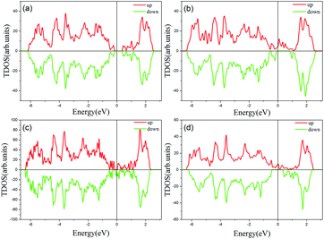
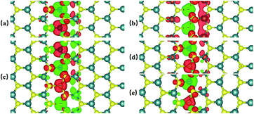
Previous studies have shown that monolayer MoS2 appears to be magnetic after being doped with TM atoms,29,30 thus we should firstly consider the magnetic exchange coupling between Cr and Fe, which determines the magnetic order of Cr/Fe-chain-MoS2. To ascertain the stable magnetic state, we calculate the energy of the antiferromagnetic and ferromagnetic states for all systems, and define δE as the energy difference between the ferromagnetic and antiferromagnetic states, with the results being listed in Table 1. One can see that the systems which are antiferromagnetic are more favorable in energy than the system in the ferromagnetic state, except for FeFe-chain-MoS2. As listed in Table 1, the results show that CrCr-chain-MoS2, FeFeCrCr-chain-MoS2, and CrFeCrFe-chain-MoS2 in the antiferromagnetic state are 444 meV, 509 meV and 325 meV energetically lower than the system in the ferromagnetic state, respectively. The large difference is favorable for their high temperature application. However, for FeFe-chain-MoS2, which shows ferromagnetic coupling, its energy under the ferromagnetic state is 150 meV lower than that of the antiferromagnetic one. The results indicate that the four configurations have robust antiferromagnetic and ferromagnetic orders. To explore the electronic properties of the δ-type doped systems, we calculated their total density of states (TDOS) corresponding to stable magnetic ordering and the results are shown in Fig. 3. The results indicate that CrCr-chain-MoS2 is an anti-ferromagnetic semiconductor with a narrower band gap of about 0.6 eV, FeFeCrCr-chain-MoS2 is an anti-ferromagnetic spin-polarized metal and its spin-polarization at the Fermi level is up to 92.5%, FeFe-chain-MoS2 behaves as a half-metal with 100% spin polarization at the Fermi level, and FeCrFeCr-chain-MoS2 is a HMFi’ with 100% spin-polarization at the Fermi level although the neighboring Fe and Cr show anti-ferromagnetic coupling. To clearly understand the magnetic order, the spin-polarized charge densities (SCDs) were calculated and the results are presented in Fig. 4. The results indicate that the majority and minority SCDs are mainly concentrated around the Cr/Fe chain, and Cr/Fe induces a small spin polarization on its NN S/Mo. As for FeFe-chain-MoS2, Fe and its NN Fe share the same spin-polarization and magnetic moment, while the spin-polarization and magnetic moments of Cr with its NN Cr in CrCr-chain-MoS2 are opposite. Moreover, from Fig. 4(b), one can find that the Fe atoms of FeFe-chain-MoS2 are antiferromagnetically coupled with its NN S/Mo atoms. For the FeFeCrCr-chain-MoS2 system, as shown in Fig. 4(c), the magnetic couplings between Fe and its NN Fe as well as its NN Cr are antiferromagnetic, and the local magnetic moments of Fe1 and Fe2 (Cr1 and Cr2) in the unit cell have nearly the same values as the opposite direction, thus the overall magnetic moment of the system is zero. Although Cr and its NN Fe in FrCrFeCr-chain-MoS2 are antiferromagnetically coupled as shown in Fig. 4(d), the total magnetic moment of this system is 2 μB so it is behaving as a ferrimagnet, and the origin of this magnetism will be discussed below. The above results indicate that Cr and Fe δ doping are effective approaches to modulate the electronic and magnetic properties of MoS2. In particular, FeCrFeCr-chain-MoS2 behaves as a HMFi’ with 100% spin-polarization at the Fermi level, whose detailed magnetic coupling mechanism will be emphasized below.
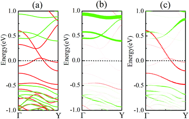
As discussed above, FeCrFeCr-chain-MoS2 behaves as a ferrimagnetic half-metal. We will focus on the origin of HMFi’ and its electronic structures. Its band structures are shown in Fig. 5, where one can see that the system is a half-metal; the spin-up channel is metallic while the spin-down channel is semiconducting with a gap (Eg) of 0.9 eV approximately. From the projection of the bands as shown in Fig. 5(b) and (c), we can see that the electrons at the Fermi level of the system are mainly derived from Fe. As mentioned above, the SCD in Fig. 4(d) indicates that Cr and Fe are anti-ferromagnetically coupled and most majority and minority SCDs localize around Fe and Cr, respectively. The band structures as shown in Fig. 5(b) and (c) indicate that around the Fermi level only the 3d states of Fe exist, and both the occupied and unoccupied 3d states of Cr are away from the Fermi level, resulting in the half-metallic characteristics of FeCrFeCr-chain-MoS2. As for the pristine monolayer MoS2, each Mo atom has six equivalent Mo–S bonds. Symmetry analysis shows that the pristine MoS2 system presents D3h symmetry. The NN S atoms of Cr/Fe in the codoped system will be no longer equivalent. However, S1 and S2, as indicated in Fig. 1, show a slight difference so they can be treated as equivalent. The total magnetic moment of FeCrFeCr-chain-MoS2 is 2 μB per unit cell, which follows the Slater–Pauling rule:48 Mt = Zt − 24, where Zt is the total number of valence electrons. The magnetic moments of the Cr and Fe atoms are −3.019 μB and 3.499 μB, respectively. Moreover, the Cr and Fe atoms further induce relatively small magnetic moments on their surrounding S and Mo atoms due to the proximity effect. The magnetic coupling between Fe and its neighboring S is ferromagnetic, while the coupling between Cr and its neighboring S is antiferromagnetic. The magnetic moments of the S atoms depend on the distance between S and Fe/Cr. S1 and S2 (as denoted in Fig. 1) have the same spin magnetic moments, and the magnetic moment of S3 is smaller than S1 and S2 but larger than S4, because the distance between S and Fe/Cr shows the sequence of  ,
,  (the
(the  were denoted in Fig. 1). The magnetic moments of S1, S2, S3, and S4 are 0.115 μB, 0.115 μB, 0.083 μB, and 0.033 μB, respectively, and the magnetic moments of the four next nearest neighbor (NNN) Mo atoms of Fe/Cr are 0.111 μB, 0.110 μB, 0.127 μB, 0.128 μB, respectively. In comparison with the free state, the magnetic moments of Cr and Fe are reduced due to the 4s electrons of Cr and Fe being transferred to MoS2 and the redistribution of the 3d electrons of Cr and Fe. To evaluate the charge transfer between Cr/Fe and MoS2, we calculated the atomic basin charge based on the atoms in molecules (AIM) theory.49 The results indicate that about one electron from the Cr/Fe atom transfers to the nearest neighbor S atom. Such electron transfer also produces a slight increase in the number of electrons in their NNN Mo atoms.
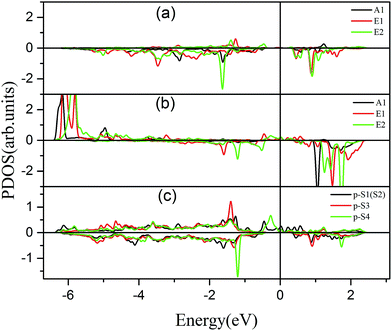
To further comprehend the mechanism of half-metallicity in FeCrFeCr-chain-MoS2, we show the partial density of states (PDOS) of Cr/Fe and their NN S atoms in Fig. 6. The 3d orbitals of Cr and Fe can be split into three classes: A1(dz2), E1(dyz, dxz), and E2(dxy, dx2−y2). As for the case of the Cr atom, in the spin-down channel, the results indicate that the A1 states are nearly occupied, and there are some unoccupied E1 and E2 state peaks located around 0.4 eV and 0.9 eV, respectively. According to the integration of the d state of the PDOS of Cr, the Cr atomic spin configuration is close to d0↑d3↓. Whereas, the d states of Fe below the Fermi level are predominantly in the majority channel, where the main peaks lie at around −6.0 eV. For the minority spin channel, the E1 and E2 states of Fe are partly occupied within a [−2.0 eV, −0.5 eV] energy window. Furthermore, the similar minority peaks for Cr and Fe around −1.7 eV indicate their coupling effect. It is worth mentioning that S1(2) has a peak in the same position, which proves that the interaction between Cr and Fe is mediated by the S between them. The Fe atomic spin configuration is close to d5↑d1↓ according to the integration of the d state of the PDOS of Fe. Contrary to Cr, with the results shown in Fig. 6(b), we can also notice that there are majority E1 and E2 states of Fe at the Fermi level. Meanwhile, the majority p states of S1(2) and S3 locate around the Fermi level indicating the coupling between S1(2) and S3 and Fe. Although there are Fe:3d–Cr:3d hybridizations through the mediating S, most of the Fe:3d majority remains non-bonding and is located around the Fermi level. Therefore, as far as the spin-up channel is concerned, FeCrFeCr-chain-MoS2 behaves as a metal.
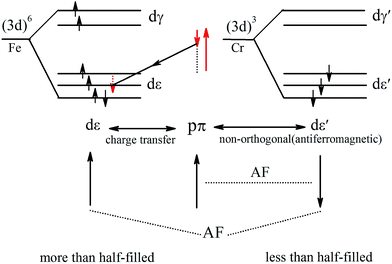
The PDOS of Cr and Fe indicate that the exchange splitting is opposite for the 3d states of Cr and Fe. Such behavior makes the local magnetic moments of the two transition-metal cations antiparallel. Therefore, we take a simplified model to analyze the magnetic coupling mechanism between Cr and Fe, as illustrated in Fig. 7. The virtual hopping of electrons between the p state of S1 and d state of Cr (Fe) follows Goodenough–Kanamori–Anderson (GKA)50,51 rules. In the model, the bond angle of Fe–S1–Cr is 83.99° (close to 90°), hence we could analyse it with 90° configurations. The pπ orbital of S1 is only non-orthogonal to dxy, so consequently a partial covalent bond between the pπ and dε [dxy] states will form. Then the electron virtual hopping occurs from the pπ orbital with the spin down state |↓> to the same unoccupied state of Fe due to Pauli’s exclusion principle. The remaining pσ orbital (spin-up state), which is non-orthogonal to dε′, antiferromagnetically couples to the dε′ orbitals of Cr. Thus the resultant superexchange interaction between Cr and Fe is antiferromagnetically coupled.
As mentioned above, FeCrFeCr-chain-MoS2 behaves as a HMFi’, showing a net 2 μB magnetic moment per unit-cell. Such magnetic properties will form a stray field in the system, which inevitably reduces the efficiency of the spin filter along the δ-type TM nano wire. Theoretical calculations have proven that external strain is an effective method to modulate the magnetism of 2D systems.32,52,53 We find that when we applied 12% compressed strain along the direction of the x-axis, the total magnetic moment can be reduced from 2 μB to 0 μB. Moreover, under such strain, antiferromagnetic coupling is still the favorable state for the system as the SCD results indicated in Fig. 4(e). The band structures of FeCrFeCr-chain-MoS2 under 12% compression, as shown in Fig. 8(a), indicate that the system transforms to a half-semiconductor, in which the VBM and CBM are fully spin-polarized with the same spin-up channel exhibiting about a 0.3 eV band gap. Fig. 8(b) and (c) show that the states of the VBM result from Fe and the states of the CBM derive from the hybrid of Cr and Fe. The results indicate that the magnetic properties of FeCrFeCr-chain-MoS2 can be effectively modulated with external strain producing its flexibility for applications in spintronics. Finally, it is worth noting that there are a lot of reports54,55 on the line defects in two dimensional MoS2 in experiments which may be the templates of the δ type doping. Considering the interesting properties of Fe/Cr δ type doped MoS2, we are looking forward to the confirmation in experiments soon.
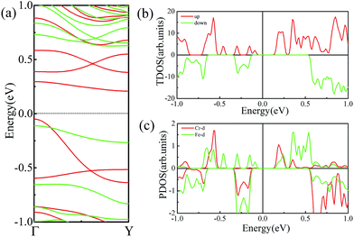 | ||
| Fig. 8 (a) Band structures of FeCrFeCr-chain-MoS2 under 12% compression strain. The Fermi level is set to zero. The TDOS and PDOS of Cr and Fe d orbitals are shown in (b) and (c), respectively. | ||
4 Conclusions
In the present work, we employed first-principles calculations to study the electronic and magnetic properties of Cr and Fe δ-type doped single layer MoS2. Our results demonstrate that Cr and Fe δ-type doping greatly influences the magnetic and electronic properties of monolayer MoS2, especially in the Cr and Fe alternatively codoped monolayer MoS2 (FeCrFeCr-chain-MoS2) which exhibits half-metallic ferrimagnetic properties with a 2 μB magnetic moment per unit cell. We analyzed the magnetic interaction of Cr/Fe and the nearest neighbor S atom, and found an interesting phenomenon: S is ferromagnetically coupled with Fe, and simultaneously antiferromagnetically coupled with Cr. Subsequently, we applied strain to modulate the magnetism. The magnetic moment turns from an initial 2 μB to 0 μB under 12% compression along the x-axis. The half-metallic ferrimagnetism in the monolayer MoS2 not only provides potential applications in spintronics, but also offers guidance for the implementation of half-metallic antiferromagnetism in two-dimensional materials.Acknowledgements
This work is supported by the National Natural Science Foundation of China (Grant No. 11574260) and scientific research innovation project of Hunan Province (CX2015B219).References
- R. A. de Groot, F. M. Mueller, P. G. v. Engen and K. H. J. Buschow, Phys. Rev. Lett., 1983, 50, 2024–2027 CrossRef CAS.
- B. I. Min, M. S. Park and J. H. Park, J. Phys.: Condens. Matter, 2004, 16, S5509 CrossRef CAS.
- X. Hu, Adv. Mater., 2012, 24, 294–298 CrossRef CAS PubMed.
- K. Schwarz, J. Phys. F: Met. Phys., 1986, 16, L211 CrossRef CAS.
- M. Shirai, T. Ogawa, I. Kitagawa and N. Suzuki, J. Magn. Magn. Mater., 1998, 177, 1383–1384 CrossRef.
- H. van Leuken and R. A. de Groot, Phys. Rev. Lett., 1995, 74, 1171–1173 CrossRef CAS PubMed.
- W. E. Pickett, Phys. Rev. Lett., 1996, 77, 3185–3188 CrossRef CAS PubMed.
- W. E. Pickett, Phys. Rev. B, 1998, 57, 10613–10619 CrossRef CAS.
- D. Ködderitzsch, W. Hergert, Z. Szotek and W. M. Temmerman, Phys. Rev. B, 2003, 68, 125114 CrossRef.
- M. Nakao, Phys. Rev. B, 2008, 77, 134414 CrossRef.
- H. Akai and M. Ogura, Phys. Rev. Lett., 2006, 97, 026401 CrossRef CAS PubMed.
- I. Galanakis, P. Dederichs and N. Papanikolaou, Phys. Rev. B, 2002, 66, 174429 CrossRef.
- B. Huang, H. Xiang, J. Yu and S.-H. Wei, Phys. Rev. Lett., 2012, 108, 206802 CrossRef PubMed.
- J. He, P. Zhou, N. Jiao, X. Chen, W. Lu and L. Z. Sun, RSC Adv., 2015, 5, 46640–46647 RSC.
- J. He, P. Lyu, L. Z. Sun, A. Morales Garcia and P. Nachtigall, J. Mater. Chem. C, 2016, 4, 6500–6509 RSC.
- K. F. Mak, C. Lee, J. Hone, J. Shan and T. F. Heinz, Phys. Rev. Lett., 2010, 105, 136805 CrossRef PubMed.
- B. Radisavljevic, A. Radenovic, J. Brivio, i. V. Giacometti and A. Kis, Nat. Nanotechnol., 2011, 6, 147–150 CrossRef CAS PubMed.
- Z. Yin, H. Li, H. Li, L. Jiang, Y. Shi, Y. Sun, G. Lu, Q. Zhang, X. Chen and H. Zhang, ACS Nano, 2012, 6, 74–80 CrossRef CAS PubMed.
- F. K. Perkins, A. L. Friedman, E. Cobas, P. M. Campbell, G. G. Jernigan and B. T. Jonker, Nano Lett., 2013, 13, 668–673 CrossRef CAS PubMed.
- K. Chang and W. Chen, ACS Nano, 2011, 5, 4720–4728 CrossRef CAS PubMed.
- N. Choudhary, J. Park, J. Y. Hwang and W. Choi, ACS Appl. Mater. Interfaces, 2014, 6, 21215–21222 CAS.
- X. Gu, W. Cui, H. Li, Z. Wu, Z. Zeng, S.-T. Lee, H. Zhang and B. Sun, Adv. Energy Mater., 2013, 3, 1262–1268 CrossRef CAS.
- Y.-H. Lee, X.-Q. Zhang, W. Zhang, M.-T. Chang, C.-T. Lin, K.-D. Chang, Y.-C. Yu, J. T.-W. Wang, C.-S. Chang and L.-J. Li, et al., Adv. Mater., 2012, 24, 2320–2325 CrossRef CAS PubMed.
- J. N. Coleman, M. Lotya, A. ONeill, S. D. Bergin, P. J. King, U. Khan, K. Young, A. Gaucher, S. De and R. J. Smith, et al., Science, 2011, 331, 568–571 CrossRef CAS PubMed.
- B. Radisavljevic, A. Radenovic, J. Brivio, V. Giacometti and A. Kis, Nat. Nanotechnol., 2011, 6, 147–150 CrossRef CAS PubMed.
- M. Heyne, D. Chiappe, J. Meersschaut, T. Nuytten, T. Conard, H. Bender, C. Huyghebaert, I. P. Radu, M. Caymax and J.-F. de Marneffe, et al., J. Mater. Chem. C, 2016, 4, 1295–1304 RSC.
- S. Ghosh, S. Najmaei, S. Kar, R. Vajtai, J. Lou, N. Pradhan, L. Balicas, P. Ajayan and S. Talapatra, Phys. Rev. B, 2014, 89, 125422 CrossRef.
- Y. Li, Z. Zhou, S. Zhang and Z. Chen, J. Am. Chem. Soc., 2008, 130, 16739–16744 CrossRef CAS PubMed.
- Y. Wang, B. Wang, R. Huang, B. Gao, F. Kong and Q. Zhang, Phys. E, 2014, 63, 276–282 CrossRef CAS.
- X.-Q. Wang, W.-G. Chen, Z.-L. Zhu and Y. Jia, Acta Metall. Sin. (Engl. Lett.), 2015, 28, 793–798 CrossRef CAS.
- K. Dolui, I. Rungger, C. D. Pemmaraju and S. Sanvito, Phys. Rev. B, 2013, 88, 075420 CrossRef.
- J. Qi, X. Li, X. Chen and K. Hu, J. Phys.: Condens. Matter, 2014, 26, 256003 CrossRef PubMed.
- A. Ramasubramaniam and D. Naveh, Phys. Rev. B, 2013, 87, 195201 CrossRef.
- Y. Wang, S. Li and J. Yi, Sci. Rep., 2016, 6, 24153 CrossRef CAS PubMed.
- Q. Yue, S. Chang, S. Qin and J. Li, Phys. Lett. A, 2013, 377, 1362–1367 CrossRef CAS.
- Y. Cheng, Z. Zhu, W. Mi, Z. Guo and U. Schwingenschlögl, Phys. Rev. B, 2013, 87, 100401 CrossRef.
- P. Hohenberg and W. Kohn, Phys. Rev., 1964, 136, B864–B871 CrossRef.
- W. Kohn and L. J. Sham, Phys. Rev., 1965, 140, A1133 CrossRef.
- G. Kresse and J. Furthmüller, Phys. Rev. B, 1996, 54, 11169 CrossRef CAS.
- G. Kresse and J. Furthmüller, Comput. Mater. Sci., 1996, 6, 15–50 CrossRef CAS.
- W. Yao, E. Wang, H. Huang, K. Deng, M. Yan, K. Zhang, K. Miyamoto, T. Okuda, L. Li, Y. Wang, H. Gao, C. Liu, W. Duan and S. Zhou, Nat. Commun., 2017, 8, 14216 CrossRef CAS PubMed.
- M. Garnica, D. Stradi, S. Barja, F. Calleja, C. Diaz, M. Alcami, N. Martin, A. L. Vazquez de Parga, F. Martin and R. Miranda, Nat. Phys., 2013, 9, 368–374 CrossRef CAS.
- P. E. Blöchl, Phys. Rev. B, 1994, 50, 17953 CrossRef.
- G. Kresse and D. Joubert, Phys. Rev. B, 1999, 59, 1758 CrossRef CAS.
- J. P. Perdew, K. Burke and M. Ernzerhof, Phys. Rev. Lett., 1996, 77, 3865 CrossRef CAS PubMed.
- V. I. Anisimov, F. Aryasetiawan and A. Lichtenstein, J. Phys.: Condens. Matter, 1997, 9, 767 CrossRef CAS.
- X. Li, X. Wu, Z. Li, J. Yang and J. Hou, Nanoscale, 2012, 4, 5680–5685 RSC.
- I. Galanakis, K. Özdoğan, E. Şaşıoğlu and B. Aktaş, Phys. Rev. B, 2007, 75, 092407 CrossRef.
- R. Bader, Atoms in Molecules: A Quantum Theory International Series of Monographs on Chemistry, Clarendon Press, 1990 Search PubMed.
- J. B. Goodenough, J. Phys. Chem. Solids, 1958, 6, 287–297 CrossRef CAS.
- J. B. Goodenough, Phys. Rev., 1955, 100, 564 CrossRef CAS.
- H. Shi, H. Pan, Y.-W. Zhang and B. I. Yakobson, Phys. Rev. B, 2013, 88, 205305 CrossRef.
- L. Kou, C. Tang, Y. Zhang, T. Heine, C. Chen and T. Frauenheim, J. Phys. Chem. Lett., 2012, 3, 2934–2941 CrossRef CAS PubMed.
- H.-P. Komsa, S. Kurasch, O. Lehtinen, U. Kaiser and A. V. Krasheninnikov, Phys. Rev. B, 2013, 88, 035301 CrossRef.
- Z. Zhang, X. Zou, V. H. Crespi and B. I. Yakobson, ACS Nano, 2013, 7, 10475–10481 CrossRef CAS PubMed.
| This journal is © The Royal Society of Chemistry 2017 |

