 Open Access Article
Creative Commons Attribution 3.0 Unported Licence
Ultrasmall titanium oxide/titanium oxynitride composite nanoparticle-embedded carbon nanofiber mats as high-capacity and free-standing electrodes for lithium sulfur batteries†
Cho-Long Lee,
Chanhoon Kim and
Il-Doo Kim *
*
Department of Materials Science and Engineering, Korea Advanced Institute of Science and Technology (KAIST), 291 Daehak-ro, Yuseong-gu, Daejeon 34141, Republic of Korea. E-mail: idkim@kaist.ac.kr
First published on 19th September 2017
Abstract
Carbon nanofibers functionalized by ultrasmall titanium based nanoparticles were synthesized as high-performance free-standing sulfur electrodes. With their high affinity to polysulfides and high electrical conductivity, the free-standing lithium–sulfur battery electrodes showed superior cycle retention of 85% with high reversible capacity of 1107 mA h g−1 after 100 cycles at 1C.
The demand for next generation rechargeable batteries with high energy densities has been increasing due to the rapid development of wide applications from portable electronics to electric vehicles (EVs) and energy storage systems (ESS). Among many candidates for next generation rechargeable batteries, lithium sulfur (Li–S) batteries have been intensively studied owing to their extremely high energy density (approximately 2600 W h kg−1) which is significantly higher than that of current lithium-ion batteries (150–200 W h kg−1).1–5 However, several drawbacks remain for commercialization of current Li–S systems including (i) the poor electrical conductivity (5 × 10⁻³⁰ S cm−1) of sulfur at room temperature, (ii) the significant volume change (up to 80%) during discharge, (iii) critical safety problems arising from the use of highly reactive Li metal, and (iv) dissolution of highly soluble lithium polysulfide (Li2Sn, 4 < n < 8).6
The poor electrical conductivity of sulfur leads to use of a large amount of conductive agents which are not active in electrochemical reactions of Li–S batteries. Therefore, the use of conductive agents has to be minimized in a fixed volume of electrodes for high energy density.6,7 In addition, the highly soluble polysulfides (Li2Sx, 3 ≤ x ≤ 6) in the ether-based electrolyte migrate and deposit on the surface of Li anodes by electrical and chemical reduction, resulting in severe shuttle effect, leading to rapid capacity fading. These parasitic reactions trigger other problems including (i) consumption of active sulfur species, (ii) corrosion of Li metal surface, and (iii) polarization of Li anode arising from formation and deposition of insoluble Li2S and Li2S2. Particularly, for the protection of Li anode, lithium nitrate (LiNO3) has been investigated as an effective additive in electrolyte solution to protect Li anode.8,9 Electrolyte solution with LiNO3 reacts with Li metal to form protective surface film. However, the addition of LiNO3 cannot be a fundamental solution for dissolution of polysulfides. To prevent and/or minimize polysulfides diffusion, anchoring materials have received great attention due to their polar functional groups which effectively promote the interaction with dissolved polysulfides.10,11 Strong affinities between anchoring materials and polysulfides prevents migration of polysulfides to Li metal anodes. Among many suggested anchoring materials, transition metal oxides (e.g. Al2O3, La2O3, SiO2, and TiO2) have been great candidates due to their strong affinity with polysulfides.6,12–15 For example, Cui's group reported the sulfur cathode based on hydrogen reduced TiO2 inverse opal structure which has effectively confined polysulfides in its 3D matrix due to both physical trapping and surface chemical adsorption.6 With the unique inverse opal structure, the sulfur cathode delivered a high capacity of approximately 890 mA h g−1 after 200 cycles at a rate of 0.2C.6,14,16 However, the low active mass loading of 0.8 mg cm−2 as well as complicated synthetic process including atomic layer deposition and subsequent H2 reduction reduces feasibility of the approach taken.
Recently, the combination of liquid polysulfide (catholyte) and a free standing conductive carbon matrix has received much interest owing to its simple and facile route for confinement of liquid polysulfide into conductive matrix.11 This approach enables the sulfur active material to simply disperse and distribute in the conductive matrix without the use of conventional melt-diffusion method. However, the interaction between liquid polysulfide and the conductive carbon matrix is not sufficient due to the nonpolar nature of carbon. In order to tackle the polysulfide-shuttle issues, strong interaction between liquid polysulfide and the conductive carbon matrix is required for the catholyte system.
Herein, we report carbon nanofibers (CNFs) functionalized by ultrasmall titanium oxide/titanium oxynitride composite nanoparticles (TiO2/TiOxNy c-NPs, 2–5 nm) as high-performance free-standing lithium–sulfur battery electrodes. The ultrasmall functional titanium based nanoparticles embedded in CNFs retain high affinity with polysulfides as well as high electrical conductivity. Furthermore, the use of dissolved polysulfides in electrolyte as active materials for liquid cathode enables us to design electrodes without binder and conductive agent as well as offer a high utilization of active materials owing to high reaction activity of liquid phase. As a consequence, free-standing sulfur electrodes resulted in excellent capacity retention of 85% with high reversible capacity of 1107 mA h g−1 after 100 cycles at 1C.
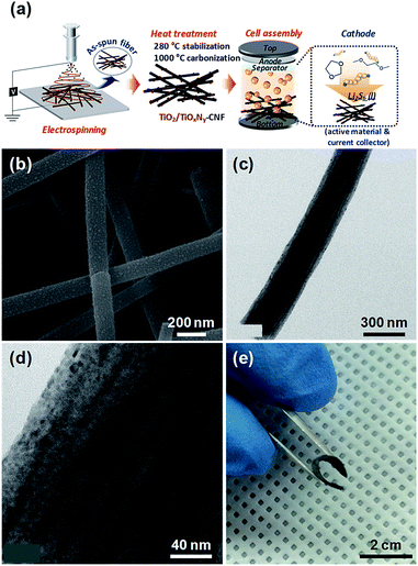
The facile synthetic route of the TiO2/TiOxNy c-NPs loaded-CNF (hereafter, TiO2/TiOxNy–CNF) mats and the configuration of Li/dissolved polysulfide electrode using the TiO2/TiOxNy–CNF mats (hereafter, TiO2/TiOxNy–CNF@PS) is schematically illustrated in Fig. 1a. The TiO2/TiOxNy–CNF mats were prepared via a simple electrospinning method followed by two-step heat treatment. The CNF backbone offers electronic pathway for active materials and empty space within nanofibers offers accommodation of volume change. The TiO2/TiOxNy c-NPs in CNFs attract polysulfides near the electrodes and help the facile kinetic reaction of lithium sulfides due to high affinity with sulfur and polysulfide species. For comparison, the pristine CNF mats (control current collector) were prepared via same electrospinning method without the addition of titanium precursor and acetic acid in electrospinning solution.
The microstructural evolution of TiO2/TiOxNy–CNF mats was characterized by transmission electron microscopy (TEM) and scanning electron microscopy (SEM). The microstructure and morphologies of the as-synthesized, stabilized, and carbonized nanofibers are shown in Fig. S1.† As shown in photograph images (Fig. S1a, d and g†), as-spun nanofibers showed white color, but their color was changed to brown and black during heat treatment. The diameter of nanofibers became thinner and finally 200 nm after carbonization (Fig. S1†). Many ultrasmall nanoparticles with the size distribution of 2–5 nm were decorated on the surface of carbonized nanofibers as shown in SEM and TEM images (Fig. 1b–d). The CNF mats including TiO2/TiOxNy–CNF showed high flexibility (Fig. 1e). The CNFs without TiO2/TiOxNy c-NPs showed similar diameters of about 200 nm while exhibiting smoother surface compared to TiO2/TiOxNy–CNF mats (Fig. S2†).
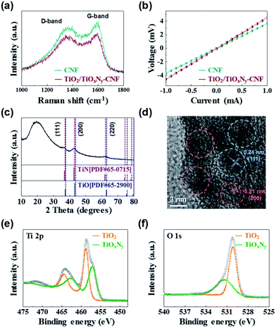
In order to investigate the carbon quality and electrical conductivity of TiO2/TiOxNy c-NPs–CNFs, we carried out Raman spectroscopy and four-probe measurement. In the Raman spectra, the peak intensity ratio of the D-band to the G-band (known as the R-value) indicates the amount of structurally ordered graphite crystallites in the carbonaceous materials (Fig. 2a).17–19 The R-value of the TiO2/TiOxNy–CNF mats was 0.91 which is almost similar to that of reference sample (0.92, CNF mat without TiO2/TiOxNy c-NPs). According to the R values, both samples exhibited disordered carbon nature. The electrical conductivity of TiO2/TiOxNy–CNF and CNF mats were 1.62 and 2.02 S cm−1, respectively materials (Fig. 2a). The crystal structure, and the phase composition of TiO2/TiOxNy–CNFs were confirmed by X-ray diffraction (XRD) analysis, high-resolution transmission electron microscopy (HRTEM), and X-ray photoelectron spectroscopy (XPS) analysis. The XRD pattern demonstrates the existence of nanoparticles loaded on CNFs, as shown in Fig. 2c. From the XRD pattern, the TiO2/TiOxNy–CNFs consisted of amorphous carbon derived from CNF mats and crystalline nanoparticles which are positioned between those for TiN (JCPDS card: no. 65-0715) and TiO (JCPDS card: no. 65-2900), exhibiting the existence of titanium oxynitride, TiOxNy. The TiNxOy is considered to be solid solution of TiN (a = 4.241 Å) and TiO (a = 4.18 Å) and its lattice parameter is between the reported values of TiO and TiN by Vegard's law.20,21 It was also confirmed by HRTEM analysis (Fig. 2d) that the fringe spacing of 2.10 ± 0.03 Å corresponds to the {200} planes, while the fringe spacing of about 2.43 ± 0.02 Å corresponds to the {111} planes. These values are between the reported values of TiO (d(200) = 2.0900 Å, d(111) = 2.4133 Å) and TiN (d(200) = 2.1200 Å, d(111) = 2.4480 Å). The results of XRD analysis and HRTEM indicated the existence of cubic phase TiOxNy.
 | ||
| Fig. 2 (a) Raman spectra and (b) I–V curves of TiO2/TiOxNy–CNF and CNF mats. (c) XRD pattern, (d) HRTEM analysis, and (e and f) XPS analysis of TiO2/TiOxNy–CNF mats. | ||
We further carried out XPS analysis to characterize the chemical compositions of the TiO2/TiOxNy NPs decorated on the CNFs. The binding energies were calibrated with respect to the C 1s peak at 284.5 eV. According to the XPS spectrum survey, all the peaks can be assigned to elemental O, Ti, N and the Ti 2p3/2 photoemission line can be fitted into two components at 457.08 eV and 458.74 eV, which correspond to TiOxNy and TiO2, respectively (Fig. 2e).22–26 These values are consistent with the spectra of O 1s photoelectrons (Fig. 2f), composed of two components centered at 530.18 and 531.36 eV, which are characteristic peaks of TiO2 and TiOxNy, respectively.22,24,25 Interestingly, the TiO2 phase was detected by the XPS analysis which was not shown in the XRD analysis. It could be attributed to the existence of amorphous TiO2.21,27,28 According to the XPS, XRD, and HRTEM analyses, as-synthesized NPs loaded on the CNFs were confirmed as the composite of TiO2 and TiOxNy.
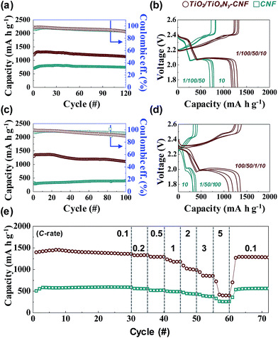
Due to the high flexibility of as-synthesized free-standing TiO2/TiOxNy–CNF mats, they can be used as 3D current collector without using conventional Al metal foil. The Li2S6 solution was prepared for the liquid cathode through a chemical reaction between sulfur (S) and lithium sulfide (Li2S). 20 μl of Li2S6 solution was simply dropped on the 3D current collector and dried for 10 min in a glove box without any post annealing or vacuum processes. The active mass loading was 2 mg cm−2. Fig. S4† shows the first charge/discharge voltage profiles of Li/dissolved polysulfide electrode using the TiO2/TiOxNy–CNF mats (TiO2/TiOxNy–CNF@PS) and a Li/dissolved polysulfide electrode using the CNF mats (hereafter, CNF@PS) at 0.05C (corresponding to 89 mA g−1) between 1.7–2.6 V vs. Li/Li+. Interestingly, the typical upper voltage plateau of the Li–S cells at 2.2–2.3 V did not appear during the first discharge curve as the reaction started at Li2S6 state. The TiO2/TiOxNy–CNF@PS shows lower first discharge capacity (1094 mA h g−1) than typical first discharge capacity of S due to the use of Li2S6 instead of S. The capacity was calculated solely based on the mass of sulfur. However, the charge capacity of the TiO2/TiOxNy–CNF@PS reached to 1444 mA h g−1 during the first charge process. The CNF@PS delivered much lower initial discharge/charge capacities (661.38 and 953.63 mA h g−1) due to the poor affinity to polysulfides. Fig. 3a–d shows cycle performance and charge/discharge voltage profiles of the TiO2/TiOxNy–CNF@PS and CNF@PS at 0.2C (corresponding to 335 mA g−1) and 1C (corresponding to 1675 mA g−1) between 1.7–2.6 V vs. Li/Li+. Owing to the high affinity to polysulfides, the TiO2/TiOxNy–CNF@PS exhibits much higher reversible capacities than CNF@PS during cycling both at 0.2 and 1C, as shown in Fig. 3a–d. The TiO2/TiOxNy–CNF@PS retained high reversible capacity of 1107 mA h g−1 after 100 cycles at 1C, which was as high as 280% of the capacity of the CNF@PS cells. The increase of specific capacities of both samples during the initial few cycles at 0.2C could be attributed to the redistribution of polysulfides on the nanofiber network. The polysulfides in the nanofiber network were rearranged and positioned at electrochemically favorable sites during initial charge/discharge process.11,29,30
The rate capabilities were also measured in charge/discharge rate (0.1C–5C) between 1.7–2.6 V vs. Li/Li+ (Fig. 3e). As expected, the TiO2/TiOxNy–CNF@PS delivered much higher reversible capacities throughout all rates. The ultrasmall TiO2/TiOxNy c-NPs in CNFs significantly increased affinity to polysulfides, which resulted in highly improved reversible capacity of the cells during the cycling. Furthermore, the CNF mats provided sufficient spaces for volume change during the cycling. The synergistic coupling of both rationally designed CNF and ultrasmall TiO2/TiOxNy c-NPs resulted in the highly improved cycle and rate performances. The effect of the TiO2/TiOxNy c-NPs decreased as charge/discharge current density increased. As shown in Fig. 3e, TiO2/TiOxNy–CNF@PS and CNF@PS shows slightly different specific capacities at extremely high current density compared to low current densities, because the charge/discharge current rates were faster than the rate of drawing the polysulfides around the electrode by affinity from TiO2/TiOxNy c-NPs.
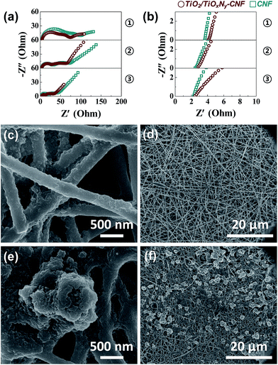
To further confirm the effect of the TiO2/TiOxNy c-NPs on the cell performance, electrochemical impedance spectroscopy (EIS) was carried out. Fig. 4a and b show the Nyquist plots of the TiO2/TiOxNy–CNF@PS and CNF@PS which were cycled for 1st discharge, and the materials were collected at the end of discharge at 1.7 V. Corresponding three points of each discharge state for impedance spectra are shown in Fig. S5.† All the spectra show two semicircles at high and medium frequencies and a linear slope at low frequencies, with corresponding equivalent circuit presented in the inset of Fig. S5.† The intercept of highest frequency on the Z′ axis is the resistance value of the electrolyte solution, i.e., RS. The RS values of the TiO2/TiOxNy–CNF@PS on three discharge states were higher (4.09, 2.84 and 2.44 Ω for state 1, 2 and 3, respectively) than those of the CNF@PS (3.63, 2.46 and 2.27 Ω for state 1, 2 and 3, respectively). The RS values are related to concentration of polysulfides on the electrode surface.31–33 Higher concentration of polysulfides on the electrode surface increases the viscosity of electrolyte and leads to increase in the RS value. Therefore, higher RS values of TiO2/TiOxNy–CNF@PS are originated from the strong polar–polar affinity of the polysulfides on the TiO2/TiOxNy c-NPs. As discharge state is deeper, RS values of both cells were smaller because most of the polysulfides on the interface of solution/electrode were already converted to the lithium sulfides. The intercepts between the medium-frequency semicircles and linear slopes on the Z′ axis are the charge transfer resistance, i.e., RCT. The RCT values are related to the reaction kinetics of the soluble polysulfides converted to the insoluble lithium sulfides.11 The TiO2/TiOxNy c-NPs facilitate precipitation and growth processes of lithium sulfide and lead to decreased RCT values of the TiO2/TiOxNy–CNF@PS. According to the EIS analysis results, the improvement of the cell performance including TiO2/TiOxNy c-NPs can be explained that the NPs attract the polysulfides around the electrode and facilitate reaction kinetics of lithium sulfides. The absorption experiment of polysulfides further supported the EIS results. As shown in Fig. S6,† the TiO2/TiOxNy–CNF shows strong absorption near 415 nm compared to the CNFs, which indicates that the TiO2/TiOxNy–CNF has the stronger entrapment ability toward Li2S6 due to the high affinity of ultrasmall TiO2/TiOxNy nanoparticles to polysulfides.34,35
 | ||
| Fig. 4 (a) Overall range and (b) expand range of the Nyquist plots of the cells using TiO2/TiOxNy–CNF and CNF current collectors after 1st discharge cycle. Ex situ SEM images of (c and d) the TiO2/TiOxNy–CNF and (e and f) CNF mats discharged for 2nd point in Fig. S4.† | ||
Furthermore, the TiO2/TiOxNy c-NPs also contributed to uniform distribution of dissolved lithium sulfides. Fig. 4c–f shows the ex situ SEM images of the TiO2/TiOxNy–CNF@PS collected at the end of discharge at 2.0 V (point 2 in Fig. S5†). According to the SEM images, relatively large reduction products with the size distribution of 1.5–4 μm were deposited on the surface of the CNF@PS, whereas very thin layers of lithium sulfides were deposited on the surface of the TiO2/TiOxNy–CNF@PS. These results indicate that the TiO2/TiOxNy–CNFs significantly contribute to uniform deposition of dissolved lithium sulfides and maintain porosity of the CNFs during cycling, which enables to achieve high reversible capacity even at high C rates.
Conclusions
In summary, we have synthesized highly flexible and conductive free-standing TiO2/TiOxNy–CNF mat by simple electrospinning method for high performance 3D current collector of Li/dissolved polysulfide cells. The electrospun structure provides empty space among nanofibers for accommodation of volume change and the TiO2/TiOxNy c-NPs with polar property not only significantly improved the redox kinetics of polysulfides, but also provided many active sites for effective deposition of lithium sulfides. Owing to the combination of functional titanium based ultrasmall nanoparticles cells and highly conductive CNFs, the TiO2/TiOxNy–CNF@PS delivered high reversible capacity of 1107 mA h g−1 after 100 cycles at 1C, respectively. Our functionalized conductive 3D current concept can be applicable to the development of next-generation sulfur batteries.Conflicts of interest
There are no conflicts of interest to declare.Acknowledgements
This work was supported by the Korea CCS R&D Center (KCRC) grant funded by the Korea government (Ministry of Science, ICT & Future Planning) (no. NRF-2014M1A8A1049303), the Korea Institute of Machinery & Materials (KIMM) and the National Research Council of Science and Technology (NST), Republic of Korea, and the Wearable Platform Materials Technology Center (WMC) funded by the National Research Foundation of Korea (NRF) Grant of the Korean Government (Ministry of Science, ICT & Future Planning) (no. 2016R1A5A1009926).References
- M.-K. Song, E. J. Cairns and Y. Zhang, Nanoscale, 2013, 5, 2186–2204 RSC.
- X. Ji and L. F. Nazar, J. Mater. Chem., 2010, 20, 9821–9826 RSC.
- P. G. Bruce, S. A. Freunberger, L. J. Hardwick and J.-M. Tarascon, Nat. Mater., 2012, 11, 19–29 CrossRef CAS PubMed.
- S. S. Zhang, J. Power Sources, 2013, 231, 153–162 CrossRef CAS.
- R. Van Noorden, Nature, 2014, 507, 26–28 CrossRef CAS PubMed.
- Z. Liang, G. Zheng, W. Li, Z. W. Seh, H. Yao, K. Yan, D. Kong and Y. Cui, ACS Nano, 2014, 8, 5249–5256 CrossRef CAS PubMed.
- C. Kim, S. Choi, S. Yoo, D. Kwon, S. Ko, J. M. Kim, S. Y. Lee, I. D. Kim and S. Park, Nanoscale, 2015, 7, 11286–11290 RSC.
- S. Xiong, K. Xie, Y. Diao and X. Hong, Electrochim. Acta, 2012, 83, 78–86 CrossRef CAS.
- S. S. Zhang, Electrochim. Acta, 2012, 70, 344–348 CrossRef CAS.
- Q. Zhang, Y. Wang, Z. W. Seh, Z. Fu, R. Zhang and Y. Cui, Nano Lett., 2015, 15, 3780–3786 CrossRef CAS PubMed.
- H. Yao, G. Zheng, P.-C. Hsu, D. Kong, J. J. Cha, W. Li, Z. W. Seh, M. T. McDowell, K. Yan, Z. Liang, V. K. Narasimhan and Y. Cui, Nat. Commun., 2014, 5, 3943 CAS.
- Y. Choi, B. Jung, D. Lee, J. Jeong, K. Kim, H. Ahn, K. Cho and H. Gu, Phys. Scr., 2007, 2007, 62 CrossRef.
- F. Sun, J. Wang, D. Long, W. Qiao, L. Ling, C. Lv and R. Cai, J. Mater. Chem. A, 2013, 1, 13283–13289 CAS.
- S. Evers, T. Yim and L. F. Nazar, J. Phys. Chem. C, 2012, 116, 19653–19658 CAS.
- Z. W. Seh, J. H. Yu, W. Li, P.-C. Hsu, H. Wang, Y. Sun, H. Yao, Q. Zhang and Y. Cui, Nat. Commun., 2014, 5, 5017 CrossRef CAS PubMed.
- Q. Pang, D. Kundu, M. Cuisinier and L. Nazar, Nat. Commun., 2014, 5, 4759 CrossRef CAS PubMed.
- P. Joshi, L. Zhang, Q. Chen, D. Galipeau, H. Fong and Q. Qiao, ACS Appl. Mater. Interfaces, 2010, 2, 3572–3577 CAS.
- B. Zhang, Y. Yu, Z. Huang, Y.-B. He, D. Jang, W.-S. Yoon, Y.-W. Mai, F. Kang and J.-K. Kim, Energy Environ. Sci., 2012, 5, 9895–9902 CAS.
- M. Zhi, A. Manivannan, F. Meng and N. Wu, J. Power Sources, 2012, 208, 345–353 CrossRef CAS.
- X. Yang, C. Li, B. Yang, W. Wang and Y. Qian, Chem. Phys. Lett., 2004, 383, 502–506 CrossRef CAS.
- M. Zukalova, J. Prochazka, Z. Bastl, J. Duchoslav, L. Rubacek, D. Havlicek and L. Kavan, Chem. Mater., 2010, 22, 4045–4055 CrossRef CAS.
- X. Song, D. Gopireddy and C. G. Takoudis, Thin Solid Films, 2008, 516, 6330–6335 CrossRef CAS.
- H. Man, Z. Cui and X. Yang, Appl. Surf. Sci., 2002, 199, 293–302 CrossRef CAS.
- F.-H. Lu and H.-Y. Chen, Surf. Coat. Technol., 2000, 130, 290–296 CrossRef CAS.
- N. C. Saha and H. G. Tompkins, J. Appl. Phys., 1992, 72, 3072–3079 CrossRef CAS.
- Z. Yang, G. Du, Q. Meng, Z. Guo, X. Yu, Z. Chen, T. Guo and R. Zeng, J. Mater. Chem., 2012, 22, 5848–5854 RSC.
- M. Drygas, C. Czosnek, R. T. Paine and J. F. Janik, Chem. Mater., 2006, 18, 3122–3129 CrossRef CAS.
- A. Trenczek-Zajac, M. Radecka, K. Zakrzewska, A. Brudnik, E. Kusior, S. Bourgeois, M. M. De Lucas and L. Imhoff, J. Power Sources, 2009, 194, 93–103 CrossRef CAS.
- C.-L. Lee and I.-D. Kim, Nanoscale, 2015, 7, 10362–10367 RSC.
- S.-H. Chung and A. Manthiram, Chem. Commun., 2014, 50, 4184–4187 RSC.
- X. Pu, G. Yang and C. Yu, J. Electrochem. Soc., 2015, 162, A1396–A1400 CrossRef CAS.
- K. Han, J. Shen, S. Hao, H. Ye, C. Wolverton, M. C. Kung and H. H. Kung, ChemSusChem, 2014, 7, 2545–2553 CrossRef CAS PubMed.
- N. A. Cañas, K. Hirose, B. Pascucci, N. Wagner, K. A. Friedrich and R. Hiesgen, Electrochim. Acta, 2013, 97, 42–51 CrossRef.
- Y. Tao, Y. Wei, Y. Liu, J. Wang, W. Qiao, L. Ling and D. Long, Energy Environ. Sci., 2016, 9, 3230–3239 CAS.
- A. Schneider, J. Janek and T. Brezesinski, Phys. Chem. Chem. Phys., 2017, 19, 8349–8355 RSC.
Footnote |
| † Electronic supplementary information (ESI) available: Experimental procedure, photograph and SEM images of as-spun, stabilized, carbonized TiO2/TiOxNy–CNF mats, high magnification and low magnification SEM images of TiO2/TiOxNy–CNF and CNF mats, XPS survey spectra of the TiO2/TiOxNy–CNF mats, the 1st discharge curve of the cells using TiO2/TiOxNy–CNF and CNF current collectors corresponding to impedance spectra, and cycle performance of the pristine cells at 1C and 0.2C. See DOI: 10.1039/c7ra00877e |
| This journal is © The Royal Society of Chemistry 2017 |


