 Open Access Article
Creative Commons Attribution 3.0 Unported Licence
Electroactive polymer/carbon nanotube hybrid materials for energy storage synthesized via a “grafting to” approach†
Bruno Ernoulda,
Olivier Bertranda,
Andrea Minoiac,
Roberto Lazzaronic,
Alexandru Vladb and
Jean-François Gohy *a
*a
aInstitute of Condensed Matter and Nanosciences (IMCN), Bio- and Soft Matter (BSMA), Université catholique de Louvain, Place L. Pasteur 1, B-1348, Louvain-la-Neuve, Belgium. E-mail: jean-francois.gohy@uclouvain.be
bInstitute of Condensed Matter and Nanosciences (IMCN), Division of Molecules, Solids and Reactivity (MOST), Université catholique de Louvain, Place L. Pasteur 1/6, B-1348 Louvain-la-Neuve, Belgium
cLaboratory for Chemistry of Novel Materials, University of Mons – UMONS, Place du Parc 20, B-7000 Mons, Belgium
First published on 20th March 2017
Abstract
This paper describes the synthesis and characterization of a new hybrid material based on poly(2,2,6,6-tetramethylpiperidin-1-oxyl-4-yl methacrylate) (PTMA) for lithium battery applications. Our strategy relies on the anchoring of nitroxide-embedding polymer chains onto multi-walled carbon nanotubes (MWCNTs). The resulting hybrid material (MWCNT-g-PTMA) not only prevents the solubilization of the PTMA active material but also benefits from its structural design aspects. The MWCNT-g-PTMA structure confers high performances thanks to the precise distribution of the PTMA redox material with respect to the MWCNT conductive network, as confirmed by molecular modeling simulations of the polymer/MWCNT interface. Physicochemical characterizations are evidence of the success of MWCNT-g-PTMA synthesis with a polymer loading up to 30 wt%. Electrochemical analysis shows the potential of MWCNT-g-PTMA as a battery material, with a capacity reaching 85% of the theoretical value, a good cyclability (retention > 80% after 150 cycles) and excellent power performances (capacity at 60C exceeding 65% of the nominal value).
Introduction
In our ever more electronic, connected and mobile world, numerous technologies of everyday life rely on working principles requiring materials exhibiting, for instance, light emission, electrochromism or electrical to chemical energy conversion. However, the devices based on these principles are often inherently linked to the use of metals that raise environmental concerns about their extraction, use/reuse and end-of-life management. Hence, more sustainable developments in our society should draw attention to alternatives that will lower the environmental impact. Among these alternatives, organic electroactive materials have the potential to give birth to disruptive technologies.1 The recent increase in research in this area can be explained by the fact that organic materials are based on abundant resources and that their synthesis can be designed to be less expensive in terms of energy consumption and waste management.2,3 For these reasons, organic electroactive materials have gained major interest for energy storage applications.Regarding electrochemical energy storage, batteries and supercapacitors are the main classes of technologies implemented nowadays in autonomous devices. Considered as a mature technology, lithium-ion batteries (LIBs) are usually implemented wherever the energy density is the key parameter, rather than the power density. Oppositely electrochemical capacitors – better known as supercapacitors – offer considerably higher power density but at the expense of the energy density. In between these technologies, there is clearly a need for technologies balancing the power and energy densities. In particular, an emerging class of devices came up to fill the gap, namely the organic radical batteries (ORBs).3,4 In an ORB, an organic radical acts as the electroactive component, typically on the cathodic side. One of the most studied materials is poly(2,2,6,6-tetramethylpiperidin-1-oxyl-4-yl methacrylate) (PTMA), a polymer bearing stable nitroxide radicals as side groups.1,3 During the charge process, the nitroxide side groups can be oxidized to oxoammonium cations, with the reverse process occurring during the discharge process. As a main benefit, PTMA-based cathodic materials for lithium batteries can display high charge/discharge rate capabilities (compared to classical transition metal oxides for LIBs)3,5 along with an interesting high electrochemical potential (3.6 V vs. Li/Li+).4,6 Yet, PTMA suffers from good solubility in standard commercial electrolytes7 and from its electric insulating behavior.3,4 To overcome these issues, the formulation of PTMA-based electrodes often incorporates a large amount of conductive carbon additives (60 to 80 wt%)3 to adsorb soluble species and support charge transport. Although adsorption reduces the solubilization, the process is not irreversible. Preventing long-term capacity fading still remains an issue.8 To address this, several solutions have been proposed, including cross-linking of the polymer,8–10 PTMA anchoring on insoluble substrates (ITO surface and silica particles)11–13 or nanostructured PTMA-based block copolymers incorporating an insoluble phase-segregated sequence.14
In the present contribution we are proposing an original grafting strategy that provides chemical anchoring between polymer chains and multi-walled carbon nanotubes (MWCNTs), with the extra advantage of favoring charge transfer and collection due the intimate contact between the two materials. Compared to our previous report on the “grafting from” approach,15 we report here on a “grafting to” strategy that offers a more convergent and efficient pathway to achieve covalent bonding between PTMA and MWCNTs. Previous reports about grafting have demonstrated that strong interactions between carbon nanotubes (CNTs) and the polymer are essential to take full advantage of the nitroxide ultrafast redox process.15,16 In other words, electroactive grafted materials provide higher power performances while maintaining the same conductive material content, thanks to robust charge storage and efficient charge transfer. Practically, our strategy relies on the synthesis of a functional polymer that is able to react at the MWCNT surface. As highlighted in the literature, covalent CNT surface modification often requires some pre-functionalization steps.17 Efficiency-wise, the first step is usually an attack on the sp2 carbon side-walls by means of a very reactive species, thus generating sites for the next steps of surface modification. These sites can be exploited to introduce moieties of interest so as to perform covalent anchoring of the functional polymer.
The strategy chosen here takes the benefits of a controlled polymerization technique that we reported earlier in order to obtain a functional block copolymer.18 This copolymer incorporates a PTMA sequence along with a sequence bearing azide functional groups. Introducing alkyne groups at the MWCNT surface then enables the anchoring of the block copolymer via the well-known copper-catalyzed azide–alkyne cycloaddition (CuAAC; Fig. 1). This strategy yields the grafted material MWCNT-g-PTMA with a PTMA content up to 30 wt% while offering superior electrochemical performance with respect to a more traditional blend of PTMA/MWCNTs.
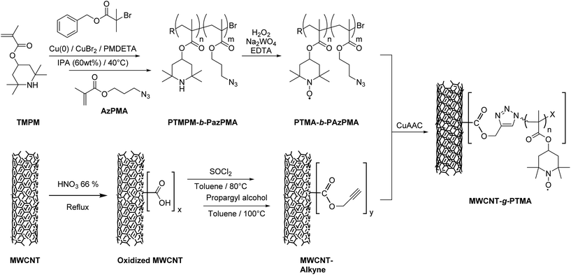 | ||
| Fig. 1 Strategy for the “grafting to” synthesis of PTMA covalently anchored on MWCNTs (MWCNT-g-PTMA). | ||
In order to gain a better understanding of the nature and strength of the PTMA/MWCNT interactions and the morphology of the interface, we have investigated model systems for the interface by means of quantum chemical and molecular modeling simulations.
Experimental
Materials
Triethylamine (analytical reagent grade, Fischer Scientific) was distilled over CaH2 under an argon atmosphere. Multi-walled carbon nanotubes (MWCNTs) NC7000 were kindly provided by Nanocyl. SOCl2 (99.5+%, Fisher Scientific), HNO3 (65%, AnalaR NORMAPUR, VWR Chemicals), anhydrous toluene (extra dry, 99.85%, over molecular sieves, AcroSeal, Acros Organics), propargyl alcohol (99%, Acros), isopropanol (IPA, 99%, Acros), sodium azide (99.9%, Acros), methacryloyl chloride (97%, containing ∼200 ppm MEHQ, Sigma-Aldrich), CuCl (99.999%, Aldrich), CuBr2 (99.999%, Aldrich), 2,2,6,6-tetramethyl-4-piperidyl methacrylate (TMPM, >98%, TCI), N,N,N′,N′′,N′′-pentamethyldiethylenetriamine (PMDETA, 98%, Aldrich), Na2WO4·2H2O (purum, ≥99%, Sigma-Aldrich), ethylenediaminetetraacetic acid disodium salt dihydrate (EDTA, 99+%, ACS reagent, Acros), anisole (99%, Acros), tris(benzyltriazolylmethyl)amine (TBTA, >97.0%, TCI), 1-methyl-2-pyrrolidone (NMP, >99.0%, TCI) and all other chemicals were used as received.Synthesis procedures
1H NMR (300 MHz, CDCl3): 6.11 (m, 1H, ![[double bond, length as m-dash]](https://www.rsc.org/images/entities/char_e001.gif) CH), 5.58 (m, 1H,
CH), 5.58 (m, 1H, ![[double bond, length as m-dash]](https://www.rsc.org/images/entities/char_e001.gif) CH), 4.24 (t, 2H, CH2–O), 3.52 (t, 2H, CH2–N3) and 1.91–2.02 (m, 5H, overlapping CH3–C and C–CH2–C).
CH), 4.24 (t, 2H, CH2–O), 3.52 (t, 2H, CH2–N3) and 1.91–2.02 (m, 5H, overlapping CH3–C and C–CH2–C).
1H NMR (300 MHz, CDCl3): 6.10 (m, 1H, ![[double bond, length as m-dash]](https://www.rsc.org/images/entities/char_e001.gif) CH), 5.57 (m, 1H,
CH), 5.57 (m, 1H, ![[double bond, length as m-dash]](https://www.rsc.org/images/entities/char_e001.gif) CH), 4.24 (t, 2H, CH2–O), 3.42 (t, 2H, CH2–N3) and 1.91–2.02 (m, 5H, overlapping CH3–C and C–CH2–C).
CH), 4.24 (t, 2H, CH2–O), 3.42 (t, 2H, CH2–N3) and 1.91–2.02 (m, 5H, overlapping CH3–C and C–CH2–C).
Mn (SEC) = 13![[thin space (1/6-em)]](https://www.rsc.org/images/entities/char_2009.gif) 200 g mol−1; Đ (SEC) = 1.20; 1H NMR (300 MHz, CDCl3) PTMPM60-b-PAzPMA3.6: 7.45–7.30 (b, 5H, HAr chain-end), 5.25–4.90 (b, 60H, CH–O PTMPM), 4.20–3.90 (b, 7.2H, CH2–O PAzPMA), 3.55–3.30 (b, 7.2H, CH2–N3 PAzPMA), 2.20–0.60 (b, 1292H, CH3 + CH2 backbone and side groups).
200 g mol−1; Đ (SEC) = 1.20; 1H NMR (300 MHz, CDCl3) PTMPM60-b-PAzPMA3.6: 7.45–7.30 (b, 5H, HAr chain-end), 5.25–4.90 (b, 60H, CH–O PTMPM), 4.20–3.90 (b, 7.2H, CH2–O PAzPMA), 3.55–3.30 (b, 7.2H, CH2–N3 PAzPMA), 2.20–0.60 (b, 1292H, CH3 + CH2 backbone and side groups).
Mn (SEC) = 10![[thin space (1/6-em)]](https://www.rsc.org/images/entities/char_2009.gif) 400 g mol−1; Đ (SEC) = 1.20; oxidation yield = 94%.
400 g mol−1; Đ (SEC) = 1.20; oxidation yield = 94%.
Modeling methodology
To investigate the interaction between the radical species and the nanotube wall, we evaluated the binding energy of a PTMA monomer interacting with a graphene flake by means of DFT calculations, using the Gaussian 09 package, and the uwB97xd functional and 6-31g(d) basis set. The correction for basis set superposition error has been included in the calculations.To investigate the morphology of the CNT-g-PTMA interface, we performed molecular dynamics simulations using the Materials Studio 7 (MS7) molecular modelling package. In order to properly describe the TEMPO fragments in the PTMA polymer chains, we improved the standard Amber force field, as included in the MS7 package by introducing new force field atom types and parameters taken from the work of Stendardo et al.20 The partial atomic charges for the PTMA monomer units were calculated by applying the restrained electrostatic potential (RESP)21 procedure to the potential grid computed for the PTMA monomer at the HF/6-31g(d) level of theory. Molecular dynamics (MD) simulations were performed in the NVT or NPT ensemble, where temperature and pressure were kept constant by using the Nosé–Hoover thermostat and Parrinello barostat. For all MD simulations, the time step was set to 1 fs. All polymer chains modelled were atactic, i.e., statistical PTMA polymer chains having 37 monomers, for a molecular mass of 8880 g mol−1. We will refer to these polymer chains as PTMA37. As for the nanotube, we built a periodic MWCNT composed of seven concentric tubes, the smallest one being a (44,44) SWNT with a diameter of about 6 nm, with a tube separation of 0.33 nm. The resulting MWCNT had 35![[thin space (1/6-em)]](https://www.rsc.org/images/entities/char_2009.gif) 113 carbon atoms, a periodic length of 5.165 nm and its external wall was an armchair nanotube with a diameter of about 10 nm and it contained 6216 carbon atoms. Knowing the total number of atoms in the whole MWCNT allows the calculation of a polymer grafting density in the model that matches the experimental value (see below). To keep the computational effort on a tractable level, only the external tube was included in the actual simulations of the polymer/nanotube interface; it was considered as a rigid body, to account for the MWCNT rigidity.
113 carbon atoms, a periodic length of 5.165 nm and its external wall was an armchair nanotube with a diameter of about 10 nm and it contained 6216 carbon atoms. Knowing the total number of atoms in the whole MWCNT allows the calculation of a polymer grafting density in the model that matches the experimental value (see below). To keep the computational effort on a tractable level, only the external tube was included in the actual simulations of the polymer/nanotube interface; it was considered as a rigid body, to account for the MWCNT rigidity.
Electrochemical characterizations
![[thin space (1/6-em)]](https://www.rsc.org/images/entities/char_2009.gif) :
:![[thin space (1/6-em)]](https://www.rsc.org/images/entities/char_2009.gif) 1 v/v with 1 M of lithium hexafluorophosphate (LiPF6) was purchased from Solvionic and used as the electrolyte. Cells were assembled in CR2032 coin cells. All cells were assembled under an argon atmosphere (<0.1 ppm H2O, <0.1 ppm O2) in an INERT LAB glovebox. Spare parts for the CR2032 coin cell assembly were purchased from MTI Corp.
1 v/v with 1 M of lithium hexafluorophosphate (LiPF6) was purchased from Solvionic and used as the electrolyte. Cells were assembled in CR2032 coin cells. All cells were assembled under an argon atmosphere (<0.1 ppm H2O, <0.1 ppm O2) in an INERT LAB glovebox. Spare parts for the CR2032 coin cell assembly were purchased from MTI Corp.Results and discussion
Pre-functionalization of MWCNTs into MWCNT-alkyne
As mentioned in the introduction, our “grafting to” strategy benefits from our work on the controlled synthesis of the PTMA-b-PAzPMA functional polymer.18 We demonstrated previously that copper(0)-mediated reversible-deactivation radical polymerization (Cu0-RDRP) is a powerful technique to yield PTMA-b-PAzPMA, a polymer bearing nitroxides as well as azides as pendant groups (Fig. 1).In this contribution, these azide groups are exploited to generate covalent bonding to the CNT conductive support. When it comes to azides as coupling moieties, their reacting counterparts tend to be alkynes in order to create covalent links under CuAAC conditions.19,22,23 Therefore we built our CNT pre-functionalization strategy around the formation of these alkyne functions. This strategy is very similar to the pre-functionalization procedure reported for surface-initiated radical polymerization from CNTs.15 The main difference here lies in the introduction of the alkyne functions instead of initiating groups leading to alkyne functionalized MWCNTs (MWCNT-alkyne).
MWCNT-alkyne is prepared via esterification of carboxylic functions with propargyl alcohol. These carboxylic groups are generated, among other functions, through oxidation with nitric acid24 and are activated using SOCl2 prior to their esterification. Consideration of the reactivity and density of the anchoring groups led us to use this method as these parameters can drastically influence the loading of active PTMA on the MWCNT-g-PTMA composite.
Monitoring of the pre-functionalization procedure was carried out at each step using thermogravimetric analyses (TGA). MWCNT–COOH displays a 3.5 wt% weight loss between 200 °C and 500 °C while pristine MWCNTs show only a little degradation (1.5 wt%) in the same temperature range. The higher weight loss for MWCNT–COOH is indicative of the presence of oxidized functions being generated on the walls of the MWCNTs.25
Concerning MWCNT-alkyne, the weight loss in the same temperature region (200–500 °C) amounts to 4.5 wt%. The difference in weight loss between MWCNT–COOH and MWCNT-alkyne is attributed to the newly bound propargyl groups. Based on this weight loss difference (1.0 wt%) and on the molar mass of the propargyl group (39 g mol−1), the number of alkyne functions can be evaluated. The calculation leads to a value of 3 functions per 1000 carbon atoms, which is in agreement with values reported previously for esterifications performed using comparable procedures.26
Synthesis of the PTMA-based polymers
In the context of the present work, we were aiming to obtain polymers that were able to react efficiently with MWCNT-alkyne while maximizing the amount of electroactive material (PTMA) both in the polymer and the resulting MWCNT-g-PTMA composites. Considering this prerequisite, we designed the polymers to incorporate a minimum amount of the azide-containing units (AzPMA). Although controlled techniques such as SET-LRP or SARA-ARTP have been acknowledged to afford well-defined polymers, feeding the reaction with a single AzPMA unit per propagating group does not ensure that every chain will actually incorporate one azide unit (even if this is statistically true). For this reason, we fed the medium with 2 to 3 AzPMA monomer molecules per polymer chain, depending on the targeted degree of polymerization (DP).For the grafting experiments, we synthesized two copolymers, PTMA37-b-PAzPMA2.5 and PTMA60-b-PAzPMA3.6. PTMA35 and PTMA69 homopolymers were also synthesized using the same Cu0-RDRP technique, as reference ‘dummy’ materials to highlight the interest of the grafting procedure. These homopolymers display overall DPs comparable to PTMA37-b-PAzPMA2.5 and PTMA60-b-PAzPMA3.6.
All the PTMA-based polymers were obtained after oxidation of the corresponding PTMPM derivatives with Na2WO4/H2O2. This chemical oxidation converts the amine functions of the TMPM units into nitroxides. Table 1 lists some of the characteristics of the PTMA polymers. The degrees of oxidation are almost quantitative, as evidenced by means of UV-Vis spectroscopy using TEMPO-tert-butyrate in CH2Cl2 for calibration (details about the procedure are provided in the ESI and Fig. S1†). The degrees of polymerization were determined for the PTMPM derivatives based on 1H NMR measurements (Fig. S2 and S3†) and the controlled character of the polymerization was confirmed through recording the GPC chromatograms (low dispersity, Đ < 1.2, Fig. S4†).
| Entrya | Mnb [g mol−1] | Đb | Oxidation yieldc [%] |
|---|---|---|---|
| a Determined by 1H NMR on the block copolymer in CDCl3.b Determined by GPC in CHCl3/IPA/Et3N calibrated with PS standards.c Determined by UV-Vis using TEMPO-tert-butyrate calibration. | |||
| PTMPM37-b-PAzPMA2.5 | 6500 | 1.12 | — |
| PTMA37-b-PAzPMA2.5 | 6640 | 1.12 | 95.2 |
| PTMA60-b-PAzPMA3.6 | 13![[thin space (1/6-em)]](https://www.rsc.org/images/entities/char_2009.gif) 200 200 |
1.20 | 94.0 |
| PTMA35 | 5800 | 1.14 | 95.5 |
| PTMA69 | 10![[thin space (1/6-em)]](https://www.rsc.org/images/entities/char_2009.gif) 900 900 |
1.11 | 96.7 |
Retention of the azide functionality was confirmed using FT-IR measurements (Fig. S5†). Altogether these characterizations prove the viability of these copolymers as functional materials for grafting experiments.
Synthesis of MWCNT-g-PTMA via grafting to
The PTMA active material loading is one of the key parameters for the performance of our target material, i.e. MWCNT-g-PTMA. The target is to achieve a loading similar to the common value in the literature for PTMA composites (i.e. 30 wt%).3 However, concerning grafting to CNTs, reaching such loadings is often difficult. Surface functionalization by polymers via a “grafting to” approach can be challenging since the free polymer chains may have poor access to the surface, with the already anchored chains masking some of the reacting sites.27 Additionally in the case of CNTs, their propensity to self-aggregation is another delicate parameter to handle.Given these considerations, we optimized the grafting conditions via screening of some relevant parameters, such as the nature of the polymer (PTMA or PTMPM derivative), the nature of the ligand for the CuAAC, the reaction solvent, the polymer to MWCNT-alkyne weight ratio and the DP of the polymer to graft. TGA measurements were systematically performed to evaluate the influence of these parameters on the polymer material loading. As a starting point, some parameters were set for the grafting syntheses, such as the catalyst (CuCl), the ligand (N,N,N′,N′′,N′′-pentamethyldiethylenetriamine, PMDETA) and the relative amount of polymer (200 mg) to MWCNT-alkyne (20 mg) (weight ratio = 10).
The first parameter is the nature of the polymer to be grafted. For efficiency reasons, a synthetic pathway is more advantageous when it is convergent. In this regard, the grafting would be more expedient if it were involving PTMA-b-PAzPMA rather than PTMPM-b-PAzPMA. Incidentally the grafting of the former allows more comprehensive characterization of the polymer chains.
Nevertheless, one can expect differences between PTMPM and PTMA in terms of polymer loading in the resulting hybrid materials. Other things being equal, PTMA37-b-PAzPMA2.5 and PTMPM37-b-PAzPMA2.5 originating from the same polymerization batch were engaged in comparative grafting experiments. The TGAs obtained from both experiments are typical for those systems and very similar to those obtained previously with our “grafting from” approach (Fig. 2).15 The TGA experiments have been conducted under a nitrogen flow to avoid degradation of the MWCNTs and to obtain more reliable results. From the TGA recordings, the resulting MWCNT-g-PTMA displays a slightly higher polymeric content (24.0 wt%) compared to MWCNT-g-PTMPM (23.7 wt%).‡
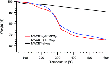 | ||
| Fig. 2 TGA thermograms of MWCNT-g-PTMPM37 and MWCNT-g-PTMA37 grafted materials. The curve obtained for alkyne-functionalized MWCNTs (MWCNT-alkyne) is also shown. | ||
Since no benefits in terms of loading were observed when grafting PTMPM derivatives, PTMA-b-PAzPMA was chosen as the polymer to graft.
The catalytic system is often considered as a critical parameter for the efficiency of CuAAC. Notably the catalytic activity can be modulated by the ligand surrounding the metal center. Though PMDETA is often chosen, this ligand is not the most activating for CuAAC by far.23 As an alternative, a grafting synthesis with the more active tris(benzyltriazolylmethyl)amine ligand (TBTA) was also conducted but it afforded no polymer loading improvement (23.2 wt% loss).
The surface chemistry of particles is also dependent on the availability of the surface to the dissolved coupling molecules. Related to that, the quality of particle dispersion can influence the yield of the reaction. N-Methyl-2-pyrrolidone (NMP) is typically a solvent recognized as an excellent dispersant for MWCNTs.28 However, the grafting experiments using NMP instead of anisole afforded MWCNT-g-PTMA with no increase in polymer loading (23.4 wt%). Seemingly the availability of the surface and the activity of the catalyst are not parameters that can be changed to permit us to reach towards the 30 wt% target.
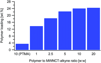
The next parameter tested was the polymer to MWCNT-alkyne weight ratio. The ratios are defined as the mass of PTMA37-b-PAzPMA2.5 relative to the mass of MWCNT-alkyne (ranging from 1 to 20). Practically we varied the mass of polymer, while all the other parameters remaining identical. From the TGAs, the loading of PTMA in the synthesized material increased with the ratio, as expected (Fig. 3). However, considering that the highest two ratios tested (10 and 20) presented very close loading values (24.0 and 24.6 wt%), the polymer content in the MWCNT-g-PTMA seems to level off at this point.
From these results, we infer that by increasing the amount of polymer with respect to the substrate, at some stage accessibility to the surface becomes an issue. In other words, the reacting groups of the polymer may be unable to interact with the anchoring points on the substrate due to steric hindrance by the already attached polymer chains. This kind of phenomenon is well-known when dealing with “grafting to” approaches applied to flat substrates29 and seems to also occur with the present system.
And yet, high surface area materials like MWCNTs are inherently prone to physisorption phenomena that can sometimes be difficult to distinguish from chemisorption. To settle this matter, a blank experiment involving a dummy polymer was conducted. The dummy compound was a linear PTMA35 homopolymer exhibiting a DP close to that of the functional PTMA37-b-PAzPMA2.5. This PTMA35 was submitted to exactly the same treatments in the presence of MWCNT-alkyne (ratio w/w = 10). As for the grafting experiments, extensive washing of the recovered material was performed until no polymer residue could be found in the filtrate after evaporation to dryness. The TGA measurements on the recovered material displayed only a 3.5 wt% weight loss attributed to physisorbed species (Fig. 3). The considerably higher weight loss of MWCNT-g-PTMA (24.0 wt%) was then quantitatively accounting for chemically-bound PTMA.
In another attempt to reach a higher value of active material, a longer functional polymer was synthesized for the grafting experiments. This PTMA60-b-PAzPMA3.6 polymer was designed to have the same TMA to AzPMA ratio as PTMA37-b-PAzPMA2.5. The grafting experiment with this longer polymer reached our expectations, with a polymeric content comparable to the literature standards (29.5 wt%).
X-ray photoelectron spectroscopy (XPS) was used to assess the nature of the MWCNT-alkyne and MWCNT-g-PTMA60 materials. The XPS measurements indicated quite distinct surface elemental and chemical compositions for MWCNT-g-PTMA60 compared to MWCNT-alkyne. For MWCNT-g-PTMA60, the N1s, O1s and C1s surface atomic concentrations correspond to a composition close to the composition of PTMA60-b-PAzPMA3.6 and distinctly different from the composition of MWCNT-alkyne (Table 2).
| Spectral lines | MWCNT-alkyne | MWCNT-g-PTMA60 | PTMA60-b-PAzPMA3.6 |
|---|---|---|---|
| Found | Found | Expected | |
| C1s | 84.6% (284.8 eV) | 80.4% (284.8 eV) | 75.7% |
| O1s | 14.7% (532.3 eV) | 15.4% (532.5 eV) | 17.6% |
| N1s | 0.68% (402.1 eV) | 4.2% (400.5 eV) | 6.7% |
Regarding the line shape, the MWCNT-alkyne C1s signal presents a pronounced tail typical of oxidized MWCNTs.24 In contrast, MWCNT-g-PTMA60 exhibits a shoulder more characteristic of pure PTMA (Fig. 4).15 Consistent with this, C1s peak deconvolution of the hybrid material can be performed considering the three components corresponding to the O–C![[double bond, length as m-dash]](https://www.rsc.org/images/entities/char_e001.gif) O, C–(N,O) and C–(C,H) chemical states. Interestingly, the quantification of these chemical states leads to values very similar to those expected for PTMA60-b-PAzPMA3.6 (Table 3). Regarding the N1s signal of our hybrid material, the peak position (400.5 eV) is consistent with nitrogen bound to other heteroatoms. Moreover the N1s peak presents a shoulder on the high-energy side (Fig. S6†). The shape and position of the peak is consistent with the contribution of triazole rings30 overlapping the TMA unit’s signal. The XPS analyses therefore clearly highlight the presence of the grafted polymer in the hybrid material and are in agreement with a core–shell structure where the MWCNT XPS signal is hidden by the surrounding grafted polymer.
O, C–(N,O) and C–(C,H) chemical states. Interestingly, the quantification of these chemical states leads to values very similar to those expected for PTMA60-b-PAzPMA3.6 (Table 3). Regarding the N1s signal of our hybrid material, the peak position (400.5 eV) is consistent with nitrogen bound to other heteroatoms. Moreover the N1s peak presents a shoulder on the high-energy side (Fig. S6†). The shape and position of the peak is consistent with the contribution of triazole rings30 overlapping the TMA unit’s signal. The XPS analyses therefore clearly highlight the presence of the grafted polymer in the hybrid material and are in agreement with a core–shell structure where the MWCNT XPS signal is hidden by the surrounding grafted polymer.
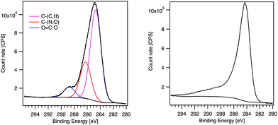 | ||
| Fig. 4 XPS C1s peaks of MWCNT-g-PTMA60 (left) and MWCNT-alkyne (right). The components obtained after fitting are displayed for MWCNT-g-PTMA60. | ||
| Components | MWCNT-g-PTMA60 | PTMA60-b-PAzPMA3.6 |
|---|---|---|
| Found | Expected | |
| C–(C,H) | 65.9% (284.6 eV) | 68.9% |
| C–(N,O) | 26.5% (286.2 eV) | 23.2% |
O![[double bond, length as m-dash]](https://www.rsc.org/images/entities/char_e001.gif) C–O C–O |
7.6% (288.7 eV) | 7.9% |
Structure of the polymer/nanotube interface
To understand in detail how the polymer chains organize at the interface with the nanotubes, the first step in the modeling studies was to investigate how the PTMA functional groups interact when adsorbed on the nanotube wall. In particular, it is essential to determine whether, upon interacting with the nanotube, (i) the radical remains localized on the nitroxide group of the PTMA unit, (ii) it becomes delocalized on the π-system of the surface, or (iii) a chemical bond forms between the NO group and the unsaturated carbon surface. The DFT results for our model system, i.e., the TEMPO fragment interacting with a graphene flake, showed that even when the nitroxide group is pointing directly towards the carbon surface (Fig. 5), there is no formation of a chemical bond nor is there delocalization of the radical, which remains fully localized on the nitroxide group. Those groups therefore remain available for redox processes.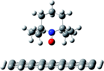 | ||
| Fig. 5 Adsorption geometry for a TEMPO fragment on a graphene flake, as a model system for the PTMA chain on the nanotube surface. | ||
This is due to the fact that the nitroxide moiety is “protected” by the four methyl groups, which keep the oxygen atom in the NO group about 0.3 nm above the carbon surface, hence suppressing any direct, strong interaction between the two species. Consistent with this, the interaction between the molecule and the carbon surface is mainly due to CH–π interactions.
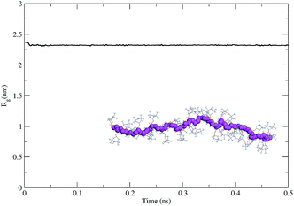
As the second step, we modeled the intrinsic behavior of the PTMA37 polymer chain. For that purpose, we performed a 500 ps-long molecular dynamics (MDs) simulation at 300 K to determine the capability of the polymer chain to coil on itself. The time evolution of the radius of gyration calculated for the polymer chain using the MDs simulation (Fig. 6) shows that PTMA37 has no strong tendency to fold on itself, meaning that the chain is rather rigid and linear.
This is probably due to steric hindrance between the TEMPO lateral groups in the monomer units and the atactic nature of the polymer chain, which does not favor the formation of organized, compact conformations (under the same conditions a polyethylene chain with the same backbone length folds readily).
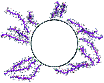
As the final step, we modeled the CNT-g-PTMA37 grafted system. Based on the experimental composition of the composite (24 wt% in polymer), we grafted 15 PTMA37 polymer chains to a 5 nm-long periodic unit cell of the model nanotube surface. Because of the high grafting density and the rigidity of the polymer chains, we performed a series of MD simulation runs in order to better explore the potential energy landscape of the system: first, a 1 ns-long MD simulation was run at 600 K, followed by a geometry minimization and a 500 ps MD run at 300 K. Fig. 7 shows the final morphology of the system: all the PTMA37 chains are mostly in an extended conformation, stretching roughly perpendicular from the nanotube surface into the surrounding medium. This organization appears to be particularly favorable in real systems because it allows for efficient interactions between each chain and both the carbon nanotube surface and the surrounding electrolyte phase. Moreover, this organization is also in perfect agreement with the experimental results that show that non-grafted PTMA (the dummy sample previously described in this contribution) is not physisorbed or wrapped around the CNT. This further justifies the need to chemically graft PTMA onto CNTs in order to obtain useful electrode materials.
Electrochemical characterizations
To proceed with the electrochemical measurements, the MWCNT-g-PTMA60 material required processing. The processing relied on a vacuum filtration method31,32 that we applied successfully in our previous work.15 More specifically, this filtration method allows the formation of MWCNT mats (buckypaper), which are obtained by successive filtrations of a first dispersion of pristine MWCNTs, followed by a second dispersion of the MWCNT-g-PTMA material. The first layer of pristine MWCNTs acts as a current collector and also permits the easy peeling of the fabric from the filter at the end of the process. Compared to our previous work, the MWCNTs for the current collector layer were kept to a minimal amount. The mixture of NMP and CH2Cl2 that was used previously as the dispersion medium for the active material here was replaced by the more benign solvent methanol.For comparison purposes, control electrodes were also prepared via a more traditional coating method (details about the preparation of which are provided in the ESI†). The coating on aluminum foils was carried out by spreading a slurry composed of the PTMA69 homopolymer, pristine MWCNTs and PVDF (30/60/10, w![[thin space (1/6-em)]](https://www.rsc.org/images/entities/char_2009.gif) :
:![[thin space (1/6-em)]](https://www.rsc.org/images/entities/char_2009.gif) w
w![[thin space (1/6-em)]](https://www.rsc.org/images/entities/char_2009.gif) :
:![[thin space (1/6-em)]](https://www.rsc.org/images/entities/char_2009.gif) w).
w).
The electrodes made of one type of active material, MWCNT-g-PTMA or PTMA69, were then assembled in a half-cell configuration vs. Li/Li+ in order to carry out the electrochemical characterization.
Cyclic voltammetry measurements were first performed to confirm the redox response of the MWCNT-g-PTMA electrodes (Fig. 8). As expected, cycling revealed a pair of clean and sharp redox peaks centered around 3.6 V, with the peak during the forward scan corresponding to the oxidation of the nitroxide into the oxoammonium cation.33 The reverse scan displays the cathodic peak corresponding to the reduction of the system. After the first cycle, the redox response was fully stable with a narrow peak-to-peak separation (ΔEp < 100 mV).
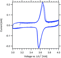 | ||
Fig. 8 Cyclic voltammograms of the MWCNT-g-PTMA60 electrode at 0.2 mV s−1 (EC/DEC 1![[thin space (1/6-em)]](https://www.rsc.org/images/entities/char_2009.gif) : :![[thin space (1/6-em)]](https://www.rsc.org/images/entities/char_2009.gif) 1 v/v; 1 M LiPF6). 1 v/v; 1 M LiPF6). | ||
The cyclability of the MWCNT-g-PTMA electrode was evaluated by means of galvanostatic charge/discharge measurements at a constant rate of C/2 (55.5 mA g−1; 1C rate = 111 mA g−1). During the first three conditioning cycles, a slight drop of the capacity was observed, which was attributed to irreversible processes (Fig. 9). Afterwards the capacity tends to stabilize at 94 mA h g−1, i.e. 85% of the theoretical 111 mA h g−1. This value is consistent with the expected 104 mA h g−1 taking into account the oxidation yield (94%) of PTMPM60-b-AzPMA3.6 into PTMA60-b-PAzPMA3.6.
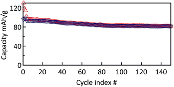 | ||
Fig. 9 Cycle stability of MWCNT-g-PTMA60 at a rate of C/2 over 150 cycles (EC/DEC 1![[thin space (1/6-em)]](https://www.rsc.org/images/entities/char_2009.gif) : :![[thin space (1/6-em)]](https://www.rsc.org/images/entities/char_2009.gif) 1 in volume; 1 M LiPF6). 1 in volume; 1 M LiPF6). | ||
Furthermore a good capacity retention was also observed after 150 cycles, with 80 mA h g−1 still being available (>80% of the nominal value). In contrast, the control electrode behaves much less efficiently under the same conditions (Fig. S7†). After the irreversible drop of the first conditioning cycles, the control electrode still displayed a pronounced fade in capacity over a few tens of cycles. After cycle 40, the capacity tends to stabilize at a value of 42 mA h g−1. This lack of performance compared to the grafted material is most probably related to the fact that the active material is not immobilized.8 The control electrodes made of PTMA69 untethered chains are likely subject to structural changes and the loss of active material through solubilization while in contact with the electrolyte solution, i.e., two processes that can be detrimental to the cycling performance.
The power capability of the electrodes was evaluated via galvanostatic measurements at variable rates (Fig. 10). The MWCNT-g-PTMA electrode displayed relatively good performances, the capacity being only slightly affected when increasing the rate from C to 10C. With regards to the charge–discharge profiles, the typical plateau of PTMA centered at 3.6 V (vs. Li/Li+)10 was only affected by polarization (<100 mV) for all rates up to 10C. Even at the highest rate of 60C (charge or discharge < 1 min), more than 65% of the nominal capacity was still available (61 mA h g−1) while the above mentioned plateau was still maintained. These rate performances underline the good electron transfer properties of the electrode made of the hybrid material. The electrode integrity after the rate capability measurements was confirmed by cycling back the electrode to lower current densities. Under these conditions the electrode displayed an appreciable recovery, obtaining nearly the same capacity as previously at the same current density.
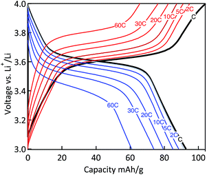 | ||
Fig. 10 Charge–discharge curves of the MWCNT-g-PTMA60 electrode at various C rates (EC/DEC 1![[thin space (1/6-em)]](https://www.rsc.org/images/entities/char_2009.gif) : :![[thin space (1/6-em)]](https://www.rsc.org/images/entities/char_2009.gif) 1 in volume; 1 M LiPF6). 1 in volume; 1 M LiPF6). | ||
From a power performance standpoint, the control and MWCNT-g-PTMA composite electrodes were also compared on the basis of their capacity retention at various C rates, as depicted in Fig. 11 (the capacities are normalized with respect to the capacity obtained at C/2). Again the comparison clearly points to MWCNT-g-PTMA offering more superior rate capabilities. The power performances of PTMA-based systems rely strongly on the electron transfer between the conductive charge and the active material9,15,34 but they can also depend on the conductivity of the overall system.35 The electrical conductivity was evaluated for both systems via 4-point probe measurements. The conductivity is 53 S cm−1 and 28 S cm−1 for the MWCNT-g-PTMA electrode and the control electrode, respectively. These values are within the same order of magnitude and cannot be solely accounting for the difference in power performances. Seemingly the higher level of homogeneity of the grafted material results in an improved support for the redox reactions by the conductive charge, as already pointed out in previous studies.9,15
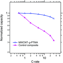 | ||
Fig. 11 Comparison of the MWCNT-g-PTMA60 and control composite electrodes on the basis of their capacity retention at various C rates (EC/DEC 1![[thin space (1/6-em)]](https://www.rsc.org/images/entities/char_2009.gif) : :![[thin space (1/6-em)]](https://www.rsc.org/images/entities/char_2009.gif) 1 in volume; 1 M LiPF6). 1 in volume; 1 M LiPF6). | ||
In every electrochemical aspect, the grafted material MWCNT-g-PTMA thus offers advantageous performances thanks to the precise distribution and anchoring of the active polymer around the conductive support.
Conclusions
This work presents an original strategy towards the successful synthesis of a MWCNT-g-PTMA hybrid material via a “grafting to” approach. The strategy takes the benefits of the synthesis of the PTMA-b-PAzPMA functional polymer via Cu0-RDRP. This polymer contains nitroxide as well as azide functionalities, the latter being involved in the tethering of the chains to the MWCNT surface. Notably, this approach allows the full characterization of the polymer prior to grafting, in particular the oxidation yield. The physicochemical characterization of the hybrid materials is consistent with their core–shell structures and demonstrates an incorporation of the electroactive polymer up to 30 wt%. Molecular modeling shows that in the core–shell structure, the grafted PTMA chains are not wrapped around the nanotubes but strongly extend from the nanotube surface into the surrounding medium, which is expected to favor interactions with the electrolyte.Electrochemical characterizations of MWCNT-g-PTMA processed as a buckypaper electrode were carried out to assess their performance in a half-cell configuration vs. Li/Li+. Galvanostatic measurements indicated excellent extraction of the theoretical capacity (85%) along with a good cycling stability (>80% retention of the initial capacity after 150 cycles). Variable-rate measurements demonstrate the ability of the material to sustain high charge/discharge current densities with the capacity exceeding 60 mA h g−1 at 60C. This approach not only affords a means to suppress the solubilization of the active material but also permits high power performances thanks to the intimate contact between PTMA and the MWCNT conductive network.
Acknowledgements
The authors are grateful to the projects BATWAL 1318146 and HYB2HYB 1410134 from the DG06 of the Service Public de Wallonie. Research in Mons is also supported by the Science Policy Office of the Belgian Government (PAI 7/5) and by FNRS-FRFC.Notes and references
- S. Muench, A. Wild, C. Friebe, B. Haeupler, T. Janoschka and U. S. Schubert, Chem. Rev., 2016, 116, 9438–9484 CrossRef CAS PubMed.
- D. Larcher and J. M. Tarascon, Nat. Chem., 2015, 7, 19–29 CrossRef CAS PubMed.
- T. Janoschka, M. D. Hager and U. S. Schubert, Adv. Mater., 2012, 24, 6397–6409 CrossRef CAS PubMed.
- H. Nishide and T. Suga, Electrochem. Soc. Interface, 2005, 14, 32–36 CAS.
- A. Vlad, N. Singh, J. Rolland, S. Melinte, P. Ajayan and J.-F. Gohy, Sci. Rep., 2014, 4, 4315 CAS.
- H. Nishide, S. Iwasa, Y.-J. Pu, T. Suga, K. Nakahara and M. Satoh, Electrochim. Acta, 2004, 50, 827–831 CrossRef CAS.
- S. Iwasa, T. Nishi and K. Nakano, NEC Tech. J., 2012, 7, 102–106 CAS.
- L. Bugnon, C. J. H. Morton, P. Novak, J. Vetter and P. Nesvadba, Chem. Mater., 2007, 19, 2910–2914 CrossRef CAS.
- A. Vlad, J. Rolland, G. Hauffman, B. Ernould and J.-F. Gohy, ChemSusChem, 2015, 8, 1692–1696 CrossRef CAS PubMed.
- F. Boujioui, O. Bertrand, B. Ernould, J. Brassinne, T. Janoschka, U. S. Schubert, A. Vlad and J.-F. Gohy, Polym. Chem., 2017, 8, 441–450 RSC.
- H.-C. Lin, C.-C. Li and J.-T. Lee, J. Power Sources, 2011, 196, 8098–8103 CrossRef CAS.
- M.-K. Hung, Y.-H. Wang, C.-H. Lin, H.-C. Lin and J.-T. Lee, J. Mater. Chem., 2012, 22, 1570–1577 RSC.
- K. Takahashi, K. Korolev, K. Tsuji, K. Oyaizu, H. Nishide, E. Bryuzgin, A. Navrotskiy and I. Novakov, Polymer, 2015, 68, 310–314 CrossRef CAS.
- G. Hauffman, A. Vlad, T. Janoschka, U. S. G. Schubert and J. Francois, J. Mater. Chem. A, 2015, 3, 19575–19581 CAS.
- B. Ernould, M. Devos, J.-P. Bourgeois, J. Rolland, A. Vlad and J.-F. Gohy, J. Mater. Chem. A, 2015, 3, 8832–8839 CAS.
- W. Choi, S. Endo, K. Oyaizu, H. Nishide and K. E. Geckeler, J. Mater. Chem. A, 2013, 1, 2999–3003 CAS.
- P.-C. Ma, N. A. Siddiqui, G. Marom and J.-K. Kim, Composites, Part A, 2010, 41, 1345–1367 CrossRef.
- O. Bertrand, B. Ernould, F. Boujioui, A. Vlad and J.-F. Gohy, Polym. Chem., 2015, 6, 6067–6072 RSC.
- B. S. Sumerlin, N. V. Tsarevsky, G. Louche, R. Y. Lee and K. Matyjaszewski, Macromolecules, 2005, 38, 7540–7545 CrossRef CAS.
- E. Stendardo, A. Pedone, P. Cimino, M. Cristina Menziani, O. Crescenzi and V. Barone, Phys. Chem. Chem. Phys., 2010, 12, 11697–11709 RSC.
- J. Wang, P. Cieplak and P. A. Kollman, J. Comput. Chem., 2000, 21, 1049–1074 CrossRef CAS.
- P. L. Golas and K. Matyjaszewski, QSAR Comb. Sci., 2007, 26, 1116–1134 CAS.
- J. E. Hein and V. V. Fokin, Chem. Soc. Rev., 2010, 39, 1302–1315 RSC.
- K. A. Wepasnick, B. A. Smith, K. E. Schrote, H. K. Wilson, S. R. Diegelmann and D. H. Fairbrother, Carbon, 2011, 49, 24–36 CrossRef CAS.
- V. Datsyuk, M. Kalyva, K. Papagelis, J. Parthenios, D. Tasis, A. Siokou, I. Kallitsis and C. Galiotis, Carbon, 2008, 46, 833–840 CrossRef CAS.
- S. Qin, D. Qin, W. T. Ford, D. E. Resasco and J. E. Herrera, J. Am. Chem. Soc., 2003, 126, 170–176 CrossRef PubMed.
- E. Beyou, S. Akbar, P. Chaumont and P. Cassagnau, in Syntheses and Applications of Carbon Nanotubes and Their Composites, InTech, 2013, ch. 5, pp. 77–115, DOI:10.5772/50710.
- K. D. Ausman, R. Piner, O. Lourie, R. S. Ruoff and M. Korobov, J. Phys. Chem. B, 2000, 104, 8911–8915 CrossRef CAS.
- B. Zhao and W. J. Brittain, Prog. Polym. Sci., 2000, 25, 677–710 CrossRef CAS.
- C. Abarca, M. M. Ali, D. Bowie and R. H. Pelton, Colloids Surf., A, 2016, 508, 192–196 CrossRef CAS.
- A. Vlad, N. Singh, C. Galande and P. M. Ajayan, Adv. Energy Mater., 2015, 5, 1402115 CrossRef.
- S. Y. Chew, S. H. Ng, J. Wang, P. Novák, F. Krumeich, S. L. Chou, J. Chen and H. K. Liu, Carbon, 2009, 47, 2976–2983 CrossRef CAS.
- K. Nakahara, S. Iwasa, M. Satoh, Y. Morioka, J. Iriyama, M. Suguro and E. Hasegawa, Chem. Phys. Lett., 2002, 359, 351–354 CrossRef CAS.
- A. Aqil, A. Vlad, M.-L. Piedboeuf, M. Aqil, N. Job, S. Melinte, C. Detrembleur and C. Jérôme, Chem. Commun., 2015, 51, 9301–9304 RSC.
- J.-K. Kim, G. Cheruvally, J.-H. Ahn, Y.-G. Seo, D. S. Choi, S.-H. Lee and C. E. Song, J. Ind. Eng. Chem., 2008, 14, 371–376 CrossRef CAS.
Footnotes |
| † Electronic supplementary information (ESI) available: Instrumentation; procedure for the oxidation degree determination of PTMA derivatives; 1H NMR of PTMPM37-b-PazPMA2.5 and PTMPM60-b-PazPMA3.6; SEC chromatograms of all polymers involved in the present work; FT-IR spectra of PTMPM37-b-PazPMA2.5 and PTMA37-b-PAzPMA2.5; N1s narrow scan of the MWCNT-g-PTMA60 material; and details about the preparation and capacity retention plot for the control electrodes. See DOI: 10.1039/c7ra02119d |
| ‡ The weight loss values presented in the “Synthesis of MWCNT-g-PTMA via grafting to” section were obtained for the 200–500 °C temperature range after subtraction of the MWCNT-alkyne contribution. |
| This journal is © The Royal Society of Chemistry 2017 |

