 Open Access Article
Creative Commons Attribution 3.0 Unported Licence
The conversion of donor to acceptor and rational design for diketopyrrolopyrrole-containing small molecule acceptors by introducing nitrogen-atoms for organic solar cells†
Jie Pana,
Hang Yina,
Yu-Zhong Xiea,
Guang-Yan Sun *a and
Zhong-Min Su
 *b
*b
aDepartment of Chemistry, Faculty of Science, Yanbian University, Yanji, 133002, People's Republic of China. E-mail: gysun@ybu.edu.cn
bInstitute of Functional Material Chemistry, Faculty of Chemistry, Northeast Normal University, Changchun 130024, People's Republic of China. E-mail: zmsu@nenu.edu.cn
First published on 21st June 2017
Abstract
For the purpose of improving the power conversion efficiencies (PCEs) of bulk heterojunction (BHJ) devices, non-fullerene small acceptors have been presented by modifying desirable donors, such as a diketopyrrolopyrrole (DPP)-based acceptor with two thiazoles, namely poly{3,6-bis(5-hexyldecyl-2thenyl)-2,5-dihydro-2,5-di(alkyl)pyrrolo[3,4]pyrrolo-1,4-dionethiazole} (PDPP2TzT), synthesized by introducing two nitrogens onto the copolymer based on DPP and terthiophene (poly[{2,5-bis(2-hexyldecyl)-2,3,5,6-tetrahydro-3,6-dioxopyrrolo[3,4-c]pyrrole-1,4-diyl}]-alt-{[2,2′:5′,2′′-terthiophene-5,5′′-diyl}]) (PDPP3T). In order to clarify the transfer mechanism, we put forward a comparative theoretical study of PDPP3T and PDPP2TzT using density functional theory/time-dependent density functional theory (DFT/TD-DFT) calculations. Subsequently, we determined that the mechanism of the conversion from a donor to an acceptor was that the insertion of nitrogen could reduce the LUMO energy by changing the electron density and intramolecular interactions. Based on this mechanism, a series of acceptors were designed with the advantages of PDPP2TzT. The results illustrate that b4 showed the best performance when blended with PDPP5T as the donor for BHJ devices. Finally, we hope our investigations will provide guidelines for further rational design of acceptor materials for BHJ devices.
1. Introduction
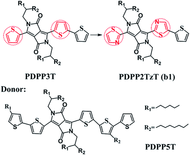
Bulk heterojunction (BHJ) devices, which exhibit clear phase separation, are famous for converting solar energy into electrical energy.1 Ordinarily, a classical BHJ device contains both donors and acceptors to enable the entire photoelectric conversion process to occur at the heterojunction interface.2 However, in contrast to the great deal of experimental and theoretical studies on electron donor materials, the electron acceptor materials have fallen far behind.3–5 For the purpose of improving the power conversion efficiencies (PCEs), more researchers have begun to pay attention to the polymer acceptors and they have determined that it is possible to secure prominent acceptors by introducing electron-withdrawing groups into low level donors. For instance, Barbarella and co-workers reported a dendritic oligothiophene-s,s-dioxide acceptor by adding oxygen to one thienyl ring of oligothiophene, and when it was combined with poly(3-hexylthiophene-2,5-diyl) (P3HT), a PCE of 0.3% could be achieved.6 Anthony and co-workers synthesized cyano-pentacene acceptors via cyano functionalization of pentacenes, finding that the energy levels would drop by 0.14 eV with the reduction of each cyano group.7 Sonar and co-workers designed a series of diketopyrrolopyrrole (DPP)-based acceptors by inserting fluoride groups, resulting in an excellent PCE as high as 2.05%.8 On this basis, Janssen and co-workers synthesized a new n-type acceptor (poly{3,6-bis(5-hexyldecyl-2thenyl)-2,5-dihydro-2,5-di(alkyl)pyrrolo[3,4]pyrrolo-1,4-dionethiazole}) (PDPP2TzT) (Fig. 1) by replacing adjacent thiophene groups in the copolymer based on DPP and terthiophene (poly[{2,5-bis(2-hexyldecyl)-2,3,5,6-tetrahydro-3,6-dioxopyrrolo[3,4-c]pyrrole-1,4-diyl}]-alt-{[2,2′:5′,2′′-terthiophene]-5,5′′-diyl}) (PDDP3T) (Fig. 1) with thiazole units and transforming the donor to an acceptor.9–14 Here, the introduction of nitrogen is performed with the aim of improving the open circuit voltage (Voc) and short-circuit current density (Jsc) by reducing the energy levels and band gap.15,16 PDPP2TzT is a promising acceptor material candidate because of its relatively low energy levels (−5.63 eV and −4.00 eV), high electron mobility (0.13 cm2 V−1 s−1), and broad infrared absorption (300–900 nm).17To the best of our knowledge, small molecule acceptor (SMA) materials, which can be acquired from polymer units, have better-defined molecular structures, higher purity without batch-to-batch variations and higher Voc than polymers.18,19 Therefore, in this context, we deeply studied the monomer of PDPP3T and PDPP2TzT (b1) as a SMA material to investigate the reason why the introduction of nitrogen made the donor convert into an acceptor using density functional theory (DFT) and time-dependent density functional theory (TD-DFT) calculations. Moreover, for the purpose of achieving a superior PCE, we designed a series of SMA materials according to the transfer mechanism of donors to acceptors. Also, we chose (poly[{2,5-bis(2-hexyldecyl)-2,3,5,6-tetrahydro-3,6-diox-opyrrolo[3,4-c]pyrrole-1,4-diyl}-alt-{[2,2′:5′,2′′pentathiophene]-5,5′′-diyl}]) (PDPP5T), which is based on DPP and penta-thiophene (Fig. 1), as the complementary donor to construct interface models, PDPP5T/b1–10.17 Some parameters such as the Frontier molecular orbitals (FMOs), energy levels, absorption spectra and charge transport abilities related to Voc, Jsc, and PCE were estimated to evaluate the performance of the SMAs in organic solar cells (OSCs).
2. Computational method
2.1. Models
According to the computed results, the alkyl-branched chains (R1 and R2, shown in Fig. 1) were proved to make no difference to the electronic structures and optical properties of the materials (shown in Table S1†), therefore these chains were replaced with hydrogen during the whole calculation for the purpose of reducing the computational cost.5,19 We tested four hybrid functions, B3LYP, PBE0, B3P86 and B3PW91, to obtain the equilibrium geometries with the 6-31G(d) basis set for the monomer models PDPP5T and PDPP2TzT.19,20 It turned out that the B3P86/6-31G(d) level is in good accordance with the experimental values; therefore, all of the ground-state geometries were optimized at this level (shown in Table S2†). As for the absorption spectra and excited-state energies, the TD-B3P86/6-31G(d) level was utilized. In addition, the fragment orbital correlation maps and charge density difference (CDD) maps, which were used to account for the conversion of the donors and acceptors, were implemented in Multiwfn 3.3.21For the interfaces, the intermolecular distance between the isolated donor and acceptor (monomer, n = 1) is a vital factor that affects the performance of the active layers.22 Therefore, we screened plenty of distances. Firstly, we made the left donor unit, the acceptor unit and the right donor unit of the donor correspond to the right donor unit, the acceptor unit and the left donor unit, respectively. This way we obtained nine distances and determined the most stable configuration when the acceptor units of the donor and acceptor corresponded, namely, X = 0 Å (shown in Table S3†). Secondly, we made 0 Å the basis and 1 Å the interval, and filtered four distances in the positive and negative direction, respectively, along the Y axis. The results are summarized in Table S4,† and indicate that Y = 2 Å gives the most stable configuration. A number of researchers have proved that 3.5 Å is the optimal distance for the Z axis of D/A interfaces, which is accordance with the similar system of Bredas and co-workers.23 Therefore, we thirdly made 3.5 Å the basis and 0.1 Å the interval, and filtered nine distances along the Z axis. The results summarized in Table S5† show that Z = 3.4 Å is the most suitable distance. Therefore, we formed face-to-face π–π stacking between the donor units, as well as the acceptor units, as the final structure (as an example, the structural model of PDPP5T/b1 is shown in Fig. S1†). Then the ground-state geometries of the PDPP5T/b1–10 interface models were optimized using the dispersion-corrected B3LYP-D3(BJ) functional with the 6-31G(d) basis set, which has been demonstrated to afford a reasonable interpretation of the interface model of heterojunction structures by Troisi and co-workers.24 To further study the relevant parameters at the D/A interface, all calculations related to excited states were evaluated by TD-DFT theory at the CAM-B3LYP/6-31G(d) level, taking long-rang correction into account, which has been proved to be suitable for evaluating the excitation energies for D/A systems.25–27 All of the above calculations were completed in the Gaussian 09 program package.28
2.2. Marcus rate expression
For the weak coupling between D and A, the non-adiabatic electron transfer theory was employed to describe the inter-CT and inter-CR. The inter-CT (kinter-CT) and inter-CR (kinter-CR) rates at the interface formed by PDPP5T and b1–b10 can be expressed by the Marcus semi-classical model:29,30
 | (1) |
3. Results and discussion
3.1. Comparative study of PDPP3T and b1
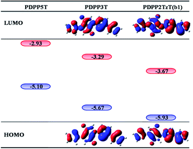
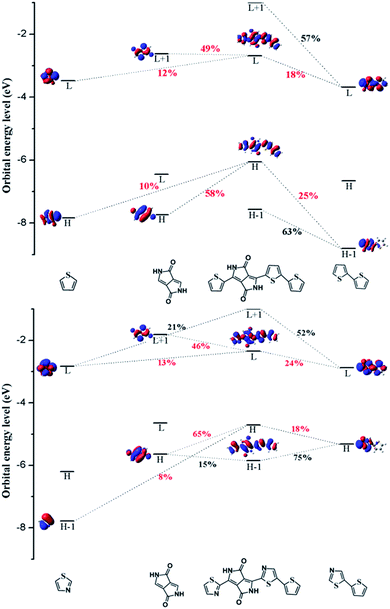
In order to investigate the mechanism via which the donor converts to an acceptor, we calculated some parameters, such as the FMOs, energy levels, CDD maps, and fragment orbital correlation maps. Then we defined PDPP5T as the donor and b1 as the acceptor to construct a BHJ device and computed some parameters concerned with the PCE.CDD is the charge density difference between the ground and excited states and can be used to analyze the charge transfer in conjugated backbones.31 Hence, we obtained CDD maps of PDPP3T and b1 to prove the deduction that the charge transfer increases with the addition of nitrogen, as shown in Fig. 4. From the plot, we can intuitively see that the predominant charge transfers for the S0 → S1 transitions of PDPP3T and b1 are practically identical. Therefore, we are left with nothing better than the second choice of S3 for PDPP3T and S4 for b1. It is obvious that the electron density of thiazole is elevated compared with thiophene due to the existence of electron-withdrawing nitrogen, which may enhance the charge transfer and the electron mobility of b1. This result is highly in agreement with the analysis of the FMOs and the fragment orbital correlation maps.
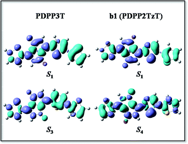 | ||
| Fig. 4 The CDD map for PDPP3T and b1 (PDPP2TzT) at the B3P86/6-31G(d) level, where the violet and turquoise colors represent an increase and a decrease in electron density, respectively. | ||
In short, we can conclude that the introduction of nitrogen can change the electron density and intramolecular interactions, which then causes the conversion of donors to acceptors.
In addition, we also figured out the energy gap, which directly determines the absorption spectra. As a consequence of the low-lying energy gap, the absorption spectrum exhibits a broad absorption in the visible region as shown in Fig. 6. Hence, the device could capture a great deal of photons and increase Jsc. Eventually we acquired the kinter-CT and kinter-CR via the Marcus rate expression to evaluate the charge separation and recombination. The result is satisfactory as the kinter-CT is large enough to cause the charge to separate and the kinter-CR is low enough to avoid charge recombination. As all of the results have indicated the electron accepting ability of b1, we infer that the introduction of nitrogen may be a helpful mechanism to design novel acceptors.
3.2. Rational design of acceptors based on b1
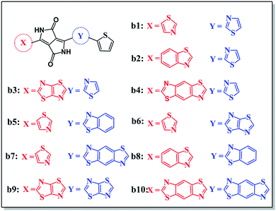
According to the mechanism above, we simultaneously designed acceptors b1–b10 with electron-withdrawing groups such as benzothiazole, thiadiazole, and benzodithiazole, which are shown in Fig. 5, and hoped to make a contribution to improve the performance of BHJ devices.All of the designed acceptors were calculated with the same methods as b1. The calculated FMOs and energy levels are displayed in Fig. S1 and S2.† As seen in the FMOs, the delocalization of b2–b10 is in accordance with that of b1, with both the HOMOs and LUMOs distributed over the whole molecule, except for in b7. In b7, there is obvious charge transfer, which means that the HOMO and LUMO are mainly delocalized at the right and left side, respectively. This may be due to the electron-donating benzodithiazole compared to the thiophene-capped diketopyrrolopyrrole (TDPP) units, which can form “push–pull” electronic structures to facilitate charge separation and tune the energy levels.33–35 However, b4, whose connection position is different from that of b7, cannot form the same peculiar structure and possesses plenty of electrons. Therefore, it is more delocalized and shows a relatively high LUMO energy level, which may enhance the Voc of the BHJ device, as seen from Table 1. In addition, we can see that the ΔEL–L of all molecules is larger than 0.3 eV, which means that efficient charge separation is guaranteed. Hence, all of the designed acceptors could be electron acceptors relative to PDPP5T.
| HOMO | LUMO | Eg | ΔEL–L | Voc | |
|---|---|---|---|---|---|
| PDPP5T | −5.10 | −2.93 | |||
| b1 | −5.93 | −3.67 | 2.26 | 0.74 | 1.13 |
| b2 | −6.01 | −3.76 | 2.25 | 0.83 | 1.04 |
| b3 | −6.05 | −3.83 | 2.22 | 0.90 | 0.97 |
| b4 | −6.07 | −3.68 | 2.39 | 0.75 | 1.12 |
| b5 | −6.12 | −3.74 | 2.38 | 0.81 | 1.06 |
| b6 | −6.04 | −3.77 | 2.27 | 0.84 | 1.03 |
| b7 | −6.04 | −3.76 | 2.28 | 0.83 | 1.04 |
| b8 | −6.19 | −3.83 | 2.36 | 0.90 | 0.97 |
| b9 | −6.05 | −3.91 | 2.14 | 0.98 | 0.89 |
| b10 | −6.29 | −3.95 | 2.34 | 1.02 | 0.85 |
The energy gap is the difference between the LUMO and HOMO, and may have an impact on the absorption properties of the molecules. Therefore, we should regard it as a reference. As shown in Fig. S2,† we can sort the energy gaps into the following order: b4 > b5 > b8 > b10 > b7 > b6 > b1 > b2 > b3 > b9. As you can see, b9 exhibits the lowest energy gap, probably because of the strongest electron-withdrawing ability of thiadiazole. Therefore, b9 may show the best conjugation and satisfactory absorption properties, which will be further discussed with reference to the absorption spectra below.
The simulated absorption spectra are provided in Fig. 6; all of the designed molecules exhibit wide absorption from 300 nm to 900 nm, which matches well with the solar spectrum. The maximum absorption peak with the largest oscillator strength mainly ranges from S0 → S1 generated by the transition from the HOMO to the LUMO, as seen in ESI Table S7.† Furthermore, the range of the maximum absorption highly overlaps with that of PDPP5T, which has been proved to be helpful for achieving high photovoltaic efficiency.36 It is worth nothing that b9 with the lowest energy gap is bathochromically shifted compared to the other molecules. As the red shift of the absorption spectrum could result in the absorption of more sunlight in the visible spectrum and increase the Jsc of the corresponding OSCs, we deduce that b9 will give a preeminent charge separation at the D/A interface, though the maximum oscillator strength is slightly lower than that of b4 and b10.5 Certainly, b4 and b10 are also capable of achieving outstanding charge separation due to their superior inter-chain π–π* stacking, which will be discussed in the following section.
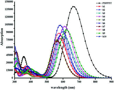 | ||
| Fig. 6 The absorption spectra of all the designed molecules b1–b10 and PDPP5T calculated at the B3P86/6-31G(d) level in a chloroform solvent. The value of the FWHM is 3000 cm−1. | ||
It is widely known that not only charge separation but also charge recombination occurs during photovoltaic conversions. Hence, both the inter-CT and inter-CR should be considered to probe the charge properties. The parameters related to inter-CT and inter-CR for S1 → S2 are summarized in Table 2. Upon inspection of Table 2, we find that b2–b10 together with PDPP5T possess comparatively high kinter-CT at about 1012 s−1 indicating the electron accepting abilities of the designed molecules. Unfortunately, we find that the kinter-CR of b10 is 1 order of magnitude larger than the kinter-CT, so the photovoltaic property of PDPP5T/b10 is doubtful. Subsequently, the kinter-CR of b9 is relatively large, which is harmful to the charge separation even though the kinter-CT is quite large. As far as we are concerned, the bigger kinter-CR originates from the inferior |ΔG| of b9 and b10, as shown in Table 2. It is widely accepted that both the intermolecular CT and CR processes are regarded as exothermic reactions (ΔG < 0).37 And the electron transfer rate will reach a maximum where the values of |ΔG| and λ are equal. When |ΔG| > λ, the electron transfer rate will increase with a decrease in the |ΔG|.19 For b4, the kinter-CT is large enough to promote charge separation and the kinter-CR is the lowest of all. This suggests that the BHJ device constructed from PDPP5T and b4 will exhibit the best photovoltaic properties. Overall, when we define PDPP5T as the donor, b4 is considered to be the most promising acceptor material because of its high LUMO energy level, broad absorption, large kinter-CT and small kinter-CT.
| λint | λext | λ | ΔGinter-CR | ΔGinter-CT | VDA | kinter-CR | kinter-CT | |
|---|---|---|---|---|---|---|---|---|
| PDPP5T/b1 | 0.33 | 0.19 | 0.52 | −1.43 | −0.83 | 0.059 | 1.64 × 10⁷ | 1.34 × 10¹³ |
| PDPP5T/b2 | 0.33 | 0.18 | 0.51 | −1.34 | −0.91 | −0.187 | 1.74 × 10⁹ | 3.94 × 10¹³ |
| PDPP5T/b3 | 0.34 | 0.18 | 0.52 | −1.27 | −0.95 | 0.067 | 2.98 × 10⁹ | 3.34 × 10¹² |
| PDPP5T/b4 | 0.34 | 0.16 | 0.50 | −1.42 | −0.97 | 0.013 | 2.93 × 10⁵ | 5.26 × 10¹⁰ |
| PDPP5T/b5 | 0.33 | 0.18 | 0.51 | 1.36 | −1.02 | 0.028 | 2.07 × 10⁷ | 1.33 × 10¹¹ |
| PDPP5T/b6 | 0.33 | 0.18 | 0.51 | −1.33 | −0.94 | 0.049 | 1.65 × 10⁸ | 1.71 × 10¹² |
| PDPP5T/b7 | 0.34 | 0.17 | 0.51 | −1.34 | −0.94 | 0.075 | 2.83 × 10⁸ | 3.40 × 10¹² |
| PDPP5T/b8 | 0.24 | 0.16 | 0.50 | −1.27 | −1.09 | 0.001 | 3.63 × 10⁶ | 4.13 × 10⁷ |
| PDPP5T/b9 | 0.34 | 0.17 | 0.51 | −1.19 | −0.95 | 0.075 | 2.08 × 10¹⁰ | 3.40 × 10¹² |
| PDPP5T/b10 | 0.34 | 0.15 | 0.49 | −1.15 | −1.19 | −0.160 | 1.13 × 10¹¹ | 3.87 × 10¹⁰ |
4. Conclusion
In summary, we have studied the mechanism of the conversion of donors to acceptors by taking the difference of PDPP3T and PDPP2TzT as an example through DFT and TD-DFT methods. The mechanism of the conversion from a donor to an acceptor is that the insertion of nitrogen reduces the LUMO energy by changing the electron density and intramolecular interactions, which can be observed from the distribution of the FMOs, the fragment orbital correlation maps and CDD maps. Furthermore, on the basis of this mechanism, we designed a series of SMAs and calculated some parameters for the PDPP5T/b1–b10 models to preliminarily characterize their performance in BHJ devices. The device not only supplies sufficient ΔEL–L to ensure exciton separation but also has a high Voc, which is beneficial to the performance of the devices. In addition, the absorption spectra are satisfactory for light absorption, which facilitates the Jsc. Sequentially, we calculated the kinter-CT and kinter-CR to clarify the electron accepting abilities of the SMAs, but unfortunately we found that the kinter-CR of b10 is larger than the kinter-CT, putting the photovoltaic properties of b10 in doubt. By integrating all of the calculated parameters we found that all of the designed molecules with electron-withdrawing groups exhibited outstanding acceptor abilities and b4 may be optimal due to its high LUMO energy level, broad absorption, and small kinter-CT. Finally, we hope that our work will provide a novel direction for designing electron acceptors and then accelerate the development of BHJ devices.Acknowledgements
We gratefully acknowledge the financial support from the National Natural Science Foundation of China (Project No. 21363025, 21463026) and the Science and Technology Development Project Foundation of Jilin Province (20150101008JC).References
- J. You, L. Dou, K. Yoshimura, T. Kato, K. Ohya, T. Moriarty, K. Emery, C. C. Chen, J. Gao and G. Li, Nat. Commun., 2013, 4, 1446–1455 CrossRef PubMed.
- G. Yu, J. Gao, J. C. Hummelen, F. Wudl and A. J. Heeger, Science, 1995, 270, 1789–1791 CAS.
- J.-Il. Park, J. W. Chung, J.-Y. Kim, J. Lee, J. Y. Jung and B. Koo, et al., J. Am. Chem. Soc., 2015, 137, 12175–12178 CrossRef CAS PubMed.
- K. H. Hendriks, G. H. L. Heintges, V. S. Gevaerts, M. M. Wienk and R. A. J. Janssen, Angew. Chem., Int. Ed., 2013, 52, 8341–8344 CrossRef CAS PubMed.
- Q. Q. Pan, S. B. Li, Y. Wu, G. Sun, Y. Geng and Z. M. Su, RSC Adv., 2016, 6, 81164–81173 RSC.
- G. Barbarella, L. Favaretto, A. Zanelli, G. Gigli, M. Mazzeo, M. Anni and A. Bongini, Adv. Funct. Mater., 2005, 15, 664–670 CrossRef CAS.
- Y. F. Lim, Y. Shu, S. R. Parkin, J. E. Anthony and G. G. Malliaras, J. Mater. Chem., 2009, 19, 3049–3056 RSC.
- P. Sonar, G. M. Ng, T. T. Lin, A. Dodabalapur and Z. K. Chen, J. Mater. Chem., 2010, 20, 3626–3636 RSC.
- H. Bronstein, Z. Chen, R. Ashraf, W. Zhang, J. Du, J. Durrant, P. Tuladhar, K. Song, S. Watkins, Y. Geerts, M. Wienk, R. Janssen, T. Anthopoulos, H. Sirringhaus, M. Heeney and I. McCulloch, J. Am. Chem. Soc., 2011, 133, 3272–3275 CrossRef CAS PubMed.
- L. Dou, G. Jing, E. Richard, J. You, C. C. Chen, K. C. Cha, Y. He, L. Gang and Y. Yang, J. Am. Chem. Soc., 2012, 134, 10071–10079 CrossRef CAS PubMed.
- S. Zhang, L. Ye, Q. Wang, Z. Li, X. Guo, L. Huo, H. Fan and J. Hou, J. Phys. Chem. C, 2013, 117, 9550–9557 CAS.
- I. Meager, R. S. Ashraf, S. Mollinger, B. C. Schroeder, H. Bronstein, D. Beatrup, M. S. Vezie, T. Kirchartz, A. Salleo and J. Nelson, J. Am. Chem. Soc., 2013, 135, 11537–11540 CrossRef CAS PubMed.
- L. Huo, S. Zhang, X. Guo, F. Xu, Y. Li and J. Hou, Angew. Chem., Int. Ed., 2011, 50, 9697–9702 CrossRef CAS PubMed.
- B. Tieke, A. R. Rabindranath, K. Zhang and Y. Zhu, Beilstein J. Org. Chem., 2010, 6, 830–845 CrossRef PubMed.
- Y. Cao, T. Lei, J. Yuan, J.-Y. Wang and J. Pei, J. Polym., 2013, 4, 5228–5236 CAS.
- B. Sun, W. Hong, Z. Yan, H. Aziz and A. Li, Adv. Mater., 2014, 26, 2636–2642 CrossRef CAS PubMed.
- W. Li, W. S. C. Roelofs, M. Turbiez, M. M. Wienk and R. A. J. Janssen, Adv. Mater., 2014, 26, 3304–3309 CrossRef CAS PubMed.
- J. Ren and M. L. Sun, Chin. J. Org. Chem., 2016, 36, 2284–2300 CrossRef CAS.
- S. B. Li, Y. A. Duan, Y. Geng, H. Z. Gao, Y. Q. Qiu and Z. M. Su, RSC Adv., 2015, 5, 29401–29411 RSC.
- Y. A. Duan, Y. Geng, H. B. Li, X. D. Tang, J. L. Jin and Z. M. Su, Org. Electron., 2012, 13, 1213–1222 CrossRef CAS.
- T. Lu and F. Chen, J. Comput. Chem., 2012, 33, 580–592 CrossRef CAS PubMed.
- K. R. Graham, C. Cabanetos, J. P. Jahnke, M. N. Idso, L. A. El, G. O. Ngongang Ndjawa, T. Heumueller, K. Vandewal, A. Salleo and B. F. Chmelka, J. Am. Chem. Soc., 2014, 136, 9608–9618 CrossRef CAS PubMed.
- M. K. Ravva, T. H. Wang and J. L. Bredas, Chem. Mater., 2016, 28, 22–25 CrossRef.
- T. Liu and A. Troisi, J. Phys. Chem. C, 2011, 115, 2406–2415 CAS.
- Y. Li, T. Pullerits, M. Zhao and M. Sun, J. Phys. Chem. C, 2011, 115, 21865–21873 CAS.
- T. Yanai, D. P. Tew and N. C. Handy, Chem. Phys. Lett., 2004, 393, 51–57 CrossRef CAS.
- E. K. U. Gross and W. Kohn, Phys. Rev. Lett., 1985, 55, 2850–2852 CrossRef CAS PubMed.
- M. J. Frisch GWT, H. B. Schlegel, G. E. S. Mar, J. R. Cheeseman, G. Scalmani, V. Barone, B. Mennucci, G. A. Petersson HN, X. L. M. Caricato, A. F. H. P. Hratch ian, G. Z. Izmaylov JB, J. L. Sonnenberg, M. E. M. Hada, K. Toyota, R. Fukuda JH, M. Ishida, T. Nakajima, Y. Honda, H. N. O. Kitao, J. T. Vreven JAM, J. E. Peralta, F. Ogliaro, M. Bearpark, J. J. Heyd EB, K. N. Kudin, V. N. Staroverov, R. Kobayashi, J. Normand, K. Raghavachari AR, S. S. I. J. C. Burant, M. C. J. Tomasi, N. Rega JMM, M. Klene, J. E. Knox, J. B. Cross, V. Ba kken, C. Adamo, J. Jaramillo RG, R. E. Stratmann, A. J. A. O. Yazyev, R. Cammi, C. Pomelli JWO, R. L. Martin, K. Morokuma, G. V. G. Z akrzewski, A. Voth PS, J. J. Dannenberg, S. Dapprich, A. D. Daniels, Ö. Farkas, J. B. Foresman JVO, J. Cioslowski and D. J. Fox, R. A. Gaussian 09, Revision A.02, Gaussian, Inc, Wallingford CT, 2009 Search PubMed.
- R. A. Marcus, Angew. Chem., Int. Ed. Engl., 1993, 32, 1111–1121 CrossRef.
- P. F. Barbara, T. J. Meyer and M. A. Ratner, J. Phys. Chem., 1996, 100, 13148–13168 CrossRef CAS.
- M. C. Scharber, D. Mühlbacher, M. Koppe, P. Denk, C. Waldauf and A. J. Heeger, et al., Adv. Mater., 2006, 18, 789–794 CrossRef CAS.
- T. Huser, M. Yan and L. J. Rothberg, Proc. Natl. Acad. Sci. U. S. A., 2000, 97, 11187–11191 CrossRef CAS PubMed.
- Y. A. Duan, Y. Geng, H. B. Li, J. L. Jin, Y. Wu and Z. M. Su, J. Comput. Chem., 2013, 34, 1611–1619 CrossRef CAS PubMed.
- M. Y. Sui, S. B. Li, Q. Q. Pan, G. Y. Sun and Y. Geng, J. Mol. Model., 2017, 23, 281–288 CrossRef PubMed.
- H. Yin, Y. Geng, G. Y. Sun and Z. M. Su, J. Phys. Chem. C, 2017, 121, 2125–2134 CAS.
- H. Yao, R. Yu, T. J. Shin, H. Zhang, S. Zhang, B. Jang, M. A. Uddin, H. Y. Woo and J. Hou, Adv. Energy Mater., 2016, 6, 742–757 Search PubMed.
- Y. Yi and V. Coropceanu, J. Mater. Chem., 2011, 21, 1479–1486 RSC.
Footnote |
| † Electronic supplementary information (ESI) available: Parametrization of reorganization energy, electronic coupling, Gibbs free energy, functional screening and interface distance screening, the open circuit voltage, short-circuit current density, Frontier molecular orbitals and energy levels for the designed molecules. See DOI: 10.1039/c7ra02360j |
| This journal is © The Royal Society of Chemistry 2017 |

