 Open Access Article
Vapor-based synthesis and micropatterning of Janus thin films with distinct surface wettability and mechanical robustness†
Yumin Ye *a and
Yu Mao*b
aFaculty of Materials Science and Chemical Engineering, Ningbo University, Ningbo 315211, China. E-mail: yeyumin@nbu.edu.cn
bDepartments of Biosystems Engineering, Oklahoma State University, Stillwater, Oklahoma 74078, USA. E-mail: yu.mao@okstate.edu
First published on 5th May 2017
Abstract
Polymeric Janus thin films were synthesized using a facile, one-step, vapor-based approach. The resultant films are comprised of two ultrathin surface layers of poly(1H,1H,2H,2H-perfluorodecyl acrylate) and poly(dimethyl amino ethyl methacrylate) hydrogel, covalently linked to a highly crosslinked bulk of poly(ethylene glycol diacrylate). Such an architecture allows distinct wetting behavior on the two surfaces while enabling the film integrity and mechanical robustness to be simultaneously achieved. Owing to the strong support from the crosslinked bulk, the Young's modulus and hardness of the Janus film were significantly improved compared with those of the polymers composing the two surface layers. The film is highly transparent across the visible light spectrum. The Janus film was further micropatterned using a templated vapor deposition method and transferred to nonplanar substrates.
Introduction
Janus thin films and membranes with markedly asymmetric surface chemistry or morphology have been garnering increasing attention recently, owing to their unique surface properties and potential applications in oil-water separation,1,2 wound dressing,3,4 transdermal drug delivery,5 transferrable superhydrophobic tapes,6 and miniature devices.7 The facile synthesis and practical application of Janus thin films, however, remains a challenge, as it requires: (1) assembling of segments with dramatically different surface properties on the two sides; and (2) ensuring the integrity and robustness of the thin films.Janus films have been fabricated by indirect methods of assembling two films with distinct properties, or film synthesis followed by asymmetric processing of film surfaces.8–10 Cheng et al. assembled Janus films with in-air superhydrophobicity on one side and underwater superoleophobicity on the other by replicating the upper and lower surface morphology of lotus leaves, respectively, followed by plasma bonding of the two segments.8 Liang et al. modified chitosan films asymmetrically with silver nanoparticles and stearic acid to obtain Janus films with hydrophilic and hydrophobic surfaces.3 Shen et al. fabricated Janus polymer films through layer-by-layer (LbL) assembly of poly(ethylenemine)–Ag+ complex and poly(acrylic acid) on Teflon substrates, followed by chemical vapor deposition of silane on one side of the film.4 The resulting film exhibited superhydrophobicity on one side and hydrophilicity on the other. Obtaining Janus structures using such methods usually involves multiple steps and careful implementation of asymmetric surface treatment that only affects one side of the film. In addition, post-treatments such as thermal4,11 or plasma-induced8 crosslinking are sometimes needed to obtain robust film structure.
Direct fabrication of Janus thin films in one step has also been reported.12–15 Stimuli-responsive catecholamine Janus films were generated at the water–air interface, and the film integrity was reinforced by further crosslinking with poly(ethylenimine).13 Janus polypyrrole films with different topographic nature on the surfaces were synthesized by electro-polymerization at the dichloromethane–water interface.14 Zhang et al. fabricated ultrathin Janus films using self-assembly of poly(acrylic acid) and alkyl azopyridine at the water–air interface, which resulted in superhydrophobic and hydrophilic properties on the two surfaces.15 Such fabrication methods require the use of two distinct phases to induce different assembly behavior towards different media for the formation of asymmetric films. To the best of our knowledge, synthesis of Janus films without the use of a liquid medium has not been reported.
Vapor deposition represents an alternative route for the fabrication of polymeric Janus thin films. The recently developed initiated chemical vapor deposition (iCVD) involves thermal decomposition of initiator vapors into free radicals in the vacuum environment, followed by polymerization of the precursor monomers.16,17 Though iCVD has limitations in incorporating inorganic components into films, it has unique advantages in fabricating polymeric films with varying composition and structures, as it allows precise control of the chemical composition at a pre-determined deposition thickness simply by varying the feed of monomer vapors in situ. The sequential deposition has created some interesting bilayer structures, with a crosslinked layer at the bottom and antimicrobial18 or water-repelling19 functionality at the top. The single-step process of simultaneous polymerization and deposition ensures the integrity of the film via covalent bonding and chain entanglement between polymer layers. In addition, the bilayer structure improves the robustness and mechanical properties of the film by crosslinking in situ and confining the functional segment at the top surface, thus eliminating the need of any post-crosslinking.
In this study, we present the fabrication of free-standing Janus thin films using a single-step process of iCVD. The vapor-based method allows construction of polymer films consisted of ultrathin surface layers with markedly asymmetric wetting properties and a highly crosslinked bulk layer to provide mechanical robustness. The monomers of dimethyl amino ethyl methacrylate (DMAEMA) and 1H,1H,2H,2H-perfluorodecyl acrylate (PFDA) were chosen as building blocks to form surface layers with hydrophilicity and hydrophobicity, respectively. The hydrophilic side of the film is composed of a highly swellable hydrogel layer, which enables self-exfoliation of the Janus film from the silicon substrate upon immersion in water. The surface properties on each side of the film, along with the bulk characteristics, including mechanical and optical properties, were investigated. Furthermore, we demonstrated that the synthesized Janus film can be micropatterned using iCVD. The micropatterned film can be easily transferred onto nonplanar substrates, indicating potential applications in transferable devices.
Experimental
Vapor deposition of Janus thin films
Vapor deposition was carried out in a custom-built deposition reactor (Sharon Vacuum) described in literature.20,21 Specifically, precursor monomers of DMAEMA (98%, Sigma-Aldrich), PFDA (97%, Sigma-Aldrich), and ethylene glycol diacrylate (EGDA, 90%, Sigma-Aldrich), and initiator tert-butyl peroxide (TBP, 98%, Sigma-Aldrich) were heated to 50 °C, 80 °C, 60 °C, and 25 °C respectively, and fed into the reactor. The reactor was equipped with parallelly arrayed Nichrome filament (Ni80/Cr20, Goodfellow) and a water-cooled stage. The flow rate of the precursor monomers and initiator was adjusted by mass flow controllers (MKS, model 1153, 1150, and 1479A), while the flow rate of the crosslinker was adjusted manually by a needle valve. The actual flow rates at different stages are listed in Table 1. During deposition, TBP was thermally decomposed in the vicinity of the heated filament and initiated the polymerization of monomers on the silicon wafer substrates placed on the water-cooled stage. The temperatures of the filament and substrates were kept at 240 °C and 35 °C, respectively, as measured by directly attached thermal couples (Omega, type K). The pressure inside the reactor was maintained at 0.25 torr through the first two stages and decreased to 0.15 torr towards the end of the deposition (Table 1) using a throttling butterfly valve (MKS, model 253B). An interferometry system with a 633 nm He–Ne laser (JDS Uniphase) was used to monitor the thickness change of polymer films on silicon wafer in situ. The collected laser signal was recorded as cycling waves, and the thickness corresponding to each cycle in interferometry was calibrated using variable-angle spectroscopic ellipsometry (VASE). All the deposition parameters were maintained the same to obtain constant deposition rate at each deposition stage, and the thickness of the Janus films was proportional to the deposition time.| Stage | Layer | FRbDMAEMA (sccm) | FRcrosslinker (sccm) | FRPFDA (sccm) | FRinitiator (sccm) | Pressure (torr) | Thickness (μm) |
|---|---|---|---|---|---|---|---|
| a The deposition conditions of the 150 nm Janus film are similar, except the deposition time of each stage is shorter. The thickness of each layer for the 150 nm Janus film is approximately 40, 70, and 40 nm for bottom, bulk, and top layers, respectively.b FR: flow rate. | |||||||
| I | Bottom layer | 1.5 | 0.2 | 0 | 0.8 | 0.25 | 0.2 |
| Transitional layer | 1.5 | 1.5 | 0 | 0.8 | 0.25 | 0.8 | |
| II | Bulk | 0 | 1.5 | 0 | 0.8 | 0.25 | 8 |
| III | Transitional layer | 0 | 1.5 | 0.4 | 0.8 | 0.25 | 0.8 |
| Top layer | 0 | 0 | 0.4 | 0.8 | 0.15 | 0.2 | |
Characterizations
The contact angles of the Janus thin films were measured at room temperature using a standard contact angle goniometer (Rame Hart, Model 250-F1) equipped with an automatic liquid dispensing system. For each measurement, a 10 μL droplet of deionized water was used, and the static contact angle was measured using images taken by a F4 series digital camera and analyzed by the DROPimage software. At least five measurements were taken on different spots of each film. The surface topography of the Janus film was examined using a Veeco Multimode SPM atomic force microscope (AFM) under the tapping mode. The morphology of the Janus film was observed using an FEI Quanta 600F scanning electron microscope (SEM). The FTIR spectra of the 10 μm film were collected by a Nicolet 6700 FTIR spectrometer under the attenuated total reflection (ATR) mode using a DTGS detector and a diamond crystal over the range of 400–4000 cm−1 at 4 cm−1 resolution. The diamond crystal allows a penetration depth of approximately 1 μm. The light transmittance of the film was measured using a UV-Vis spectrometer (Cary Bio 300, Varian) over a 350–800 nm range.Nanoindentation
Nanoindentation measurements were conducted using a Nano Indenter XP system (MTS Systems Corporation). A diamond Berkovich tip with 65.3° center line to face angle was used in all measurements. The nanoindentation tests were conducted on the hydrophobic side of the Janus film in the air at 23 °C under a relative humidity of about 50%. The resolutions for load and displacement are 50 nN and 0.01 nm, respectively. The maximum load applied was 1 mN at a loading rate of 0.02 mN s−1, and the measured indenter tip drift rate was within ±0.02 nm s−1. In all the nanoindentation tests, the indentation depths were restrained within 10% of the film thickness to minimize any substrate effects. At least five nanoindentation tests were conducted at different locations for each sample, and the load-displacement curves were recorded. Detailed calculation procedures are described in the ESI.†Micropatterning
Vapor-based micropatterning of synthesized films was conducted on the Janus film using the same iCVD process described above. A SiN mesh (DuraSiNTM, Protochips) with 2 μm holes and 2 μm hole-to-hole distance was used as the stencil mask to define the pattern. A double-layered coating of ca. 50 nm PEGDA and ca. 200 nm of PDMAEMA hydrogel was deposited, followed by lifting of the SiN mesh, leaving the micropattern on the film. The fluorescent functionalization of the patterned films was performed by placing a drop of 1% fluorescein disodium on the patterned area and let it sit for 5 min. The film was then rinsed thoroughly and dried in air. The stained patterns were observed under an Olympus BX51 epifluorescence microscope with 491 nm excitation.Results and discussion
As illustrated in Fig. 1, the Janus thin films were synthesized using a one-step, three-stage vapor deposition process by controlling the flow of monomer vapors in situ. Detailed deposition conditions are listed in Table 1. At the initial stage, monomer DMAEMA was fed into the reactor and co-polymerized with the EGDA crosslinker to form poly(dimethyl amino ethyl methacrylate) (PDMAEMA) hydrogel as the bottom layer. In the subsequent stage, the flow of DMAEMA was switched off, while the flow of EGDA continued, resulting in a bulk layer of crosslinked poly(ethylene glycol diacrylate) (PEGDA). Finally, the EGDA flow was turned off, and the PFDA vapor was fed into the reactor to synthesize poly(1H,1H,2H,2H-perfluorodecyl acrylate) (PPFDA) at the top of the film. To ensure the integrity of the film, transitional layers of crosslinked PFDA and PDMAEMA hydrogel with higher crosslinker content were deposited between the two surface layers and the bulk layer. The resulting film has ultrahigh crosslinking degree in the bulk, but enriched functionalities at the top and bottom surfaces, as to be discussed later. | ||
| Fig. 1 Three-stage vapor deposition and self-exfoliation of the Janus thin film. Included in the circle is the illustration of the ionized hydrogel after water immersion. | ||
We previously reported water absorption of iCVD PDMAEMA hydrogel greater than 16 times of its own weight due to the ionization of tertiary amine.22 Because of the high water uptake at the bottom hydrogel layer, the Janus film simply self-exfoliated in deionized water. As shown in Fig. 1, after less than three min immersion, water invaded between the film and the substrate, and the film was readily released from substrate. This self-exfoliation characteristic is desired in fabricating free-standing films,23 as it eliminates extra procedures to liberate the film from the substrate such as the use of sacrificial layers.24,25
Janus films with thickness of 150 nm and 10 μm were synthesized, as shown in Fig. 2. The compositional difference in the vertical growth direction did not cause any morphological variation across the film thickness. The 10 μm film is robust and can be easily manipulated (Fig. 2a). After exfoliating and transferring to a different substrate, the 10 μm film maintained the smooth and uniform morphology, as revealed in the cross-sectional SEM of Fig. 2b. Obviously, the swelling and de-swelling of the hydrogel in the iCVD film did not induce any wavelike ridge structure as those observed in LbL films.23 This structural stability can be attributed to the confinement of the thin hydrogel layer by the crosslinked bulk, which takes up a large portion of the film (>80%). The 150 nm film also retained the structural integrity after release from substrate, with a smooth surface void of any cracks or pinholes (Fig. 2c). Small wrinkling structure, was observed (Fig. 2d), possibly due to the ultrathin thickness of the film and the smaller portion of the crosslinked bulk (<50%).
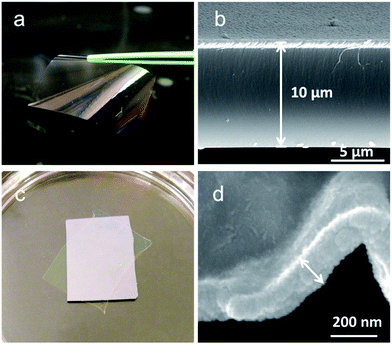 | ||
| Fig. 2 Optical and SEM images of the fabricated Janus films with thickness of 10 μm (a) and (b), and 150 nm (c) and (d). | ||
The asymmetric structure of the fabricated Janus films is illustrated in Fig. 3, with the top and bottom surfaces comprised of homopolymer PPFDA and the crosslinked PDMAEMA hydrogel, respectively. In the 10 μm Janus film, the thickness of the top hydrophobic layer and the bottom hydrophilic layer was controlled at 200 nm each (Table 1). In the 150 nm Janus film, the thickness of the top hydrophobic layer and the bottom hydrophilic layer was controlled at 40 nm each. Due to the drastic difference in the chemical composition between these two surfaces, the Janus films showed markedly distinct surface wettability. The top surface demonstrated a water contact angle of 118 ± 1°, while the bottom surface exhibited hydrophilicity with a water contact angle of 52 ± 1°.
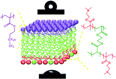 | ||
| Fig. 3 Illustrated asymmetric structure of the Janus film. The top and bottom images show shapes of water droplets on the hydrophobic and hydrophilic sides of the film, respectively. | ||
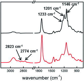
ATR-FTIR was employed to probe the composition of the near surface layers in the 10 μm Janus film. As shown in Fig. 4, the hydrophobic side of the film shows strong absorption peaks at 1146, 1201, and 1234 cm−1, which are characteristic absorption peaks of –CF2– and –CF3 moieties in PFDA.26 The absorption peak at 1732 cm−1 is designated to C![[double bond, length as m-dash]](https://www.rsc.org/images/entities/char_e001.gif) O stretching in the carbonyl groups of PFDA and EGDA. Compared with the spectrum of PPFDA homopolymer film,26 the relative intensity of C
O stretching in the carbonyl groups of PFDA and EGDA. Compared with the spectrum of PPFDA homopolymer film,26 the relative intensity of C![[double bond, length as m-dash]](https://www.rsc.org/images/entities/char_e001.gif) O stretching to C–F stretching is much higher in the Janus film. Considering that the penetration depth in the ATR measurement is greater than the thickness of the top PPFDA layer, the difference in the relative intensity indicated the incorporation of EGDA into the transitional layer beneath the top layer. On the hydrophilic side of the Janus film, the absorption peaks at 2823 and 2774 cm−1 are designated to the –CH3 stretching of tertiary amine, while the sharp peak at 1723 cm−1 stems from the C
O stretching to C–F stretching is much higher in the Janus film. Considering that the penetration depth in the ATR measurement is greater than the thickness of the top PPFDA layer, the difference in the relative intensity indicated the incorporation of EGDA into the transitional layer beneath the top layer. On the hydrophilic side of the Janus film, the absorption peaks at 2823 and 2774 cm−1 are designated to the –CH3 stretching of tertiary amine, while the sharp peak at 1723 cm−1 stems from the C![[double bond, length as m-dash]](https://www.rsc.org/images/entities/char_e001.gif) O stretching in both DMAEMA and EGDA. Again, the relative intensity of the C
O stretching in both DMAEMA and EGDA. Again, the relative intensity of the C![[double bond, length as m-dash]](https://www.rsc.org/images/entities/char_e001.gif) O stretching to the tertiary amine absorption in the Janus film is much stronger as compared with that in the PDMAEMA homopolymer film, due to the high EGDA content in the transitional layer. Neither the hydrophilic nor hydrophobic side of the film shows any trace of the characteristic peaks from their counterparts, indicating the successful decoupling of these two functional moieties.
O stretching to the tertiary amine absorption in the Janus film is much stronger as compared with that in the PDMAEMA homopolymer film, due to the high EGDA content in the transitional layer. Neither the hydrophilic nor hydrophobic side of the film shows any trace of the characteristic peaks from their counterparts, indicating the successful decoupling of these two functional moieties.
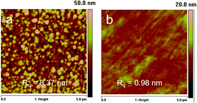
The surface topography of the Janus film was investigated using AFM (Fig. 5). The PDMAEMA hydrogel side exhibits a smooth surface with a root-mean-square roughness (Rq) of 1.0 nm, similar to that of the reported iCVD hydrogels.18,27 On the hydrophobic surface of the film, granular structures were observed possibly due to the partial segregation of the fluorinated groups.28 The nanoscale aggregates resulted in a relatively higher Rq of 8.4 nm. Nevertheless, both top and bottom surfaces were smooth compared with the microscale roughness on Janus film surfaces reported in literature.14,15,29 Therefore, although both surface chemistry and morphology contributed to the surface wettability, the asymmetry in surface wettability on the two surfaces is mainly attributed to their distinct surface chemistry.
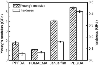
Quantifying mechanical properties is essential to assess the practical applications of Janus films. Herein, we investigated the mechanical properties of the synthesized Janus film using nanoindentation.30 Mechanical properties of vapor-deposited PDMAEMA hydrogel, PPFDA, and PEGDA films were also examined for comparison. The Young's modulus and hardness of the PPFDA film were measured to be 1.82 and 0.06 G Pa (Fig. 6), respectively, due to the weak intermolecular interaction between fluorinated chains.31 The mechanical performance is similar to that of other fluorinated polymers such as poly(tetrafluoroethylene)32 and poly((perfluoroalkyl)ethyl methacrylate).33 The Young's modulus and hardness of the PDMAEMA hydrogel were 1.12 and 0.07 G Pa, respectively. The PEGDA film, on the other hand, demonstrated a Young's modulus of 5.46 G Pa and hardness of 0.42 G Pa, owing to the cohesion of the EGDA chains and the highly crosslinked structure. Compared with the PPFDA film, the Young's modulus of the Janus film increased to 4.09 G Pa, and the hardness increased to 0.16 G Pa. The improved mechanical properties were attributed to the high crosslink density and stiff network of the PEGDA bulk layer.
To study the film stability, the Janus films were soaked in a buffer solution at pH 7 for a seven-day period. The weight loss is negligible after soaking and drying, indicating the integrity of the Janus film is ensured by the covalent linkage created between polymer chains during the single-step iCVD (Table 2). The water contact angle on the hydrophobic side decreased slightly after soaking, while the contact angle on the hydrophilic side decreased by 5°. For comparison, the contact angle change on both hydrophobic and hydrophilic sides after seven days in air was within the measurement error. Therefore, the contact angle change on the hydrophilic side after soaking was possibly due to the conformational change of polymer chains upon exposure to water. Compared with LbL films that were usually prone to degradation,34,35 the in situ crosslinking during the Janus film synthesis created polymer structure with substantially enhanced stability without any post-treatment.
| Day 0 | Day 7 | |
|---|---|---|
| θtop (°) | 118 ± 1 | 116 ± 1 |
| θbottom (°) | 52 ± 1 | 47 ± 1 |
| Weight (mg) | 36.1 | 36.0 |
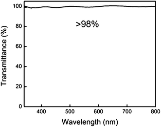
Study on the optical properties was performed by measuring the light transmittance of the Janus film over a 350–800 nm wavelength range. More than 98% of transmittance was observed across the visible light spectrum (Fig. 7) with the film thickness of 10 μm. Fluorinated polymers tend to introduce optical hazes due to crystallization and phase segregation of the fluorochemical components, which usually results in poor light transmittance.31,36 The optical transparency of the Janus film can be attributed to the ultrathin thickness of the fluorinated layer and the lower degree of fluorinated aggregates compared with that in reported iCVD PPFDA films.28
The ability to produce micropatterns on free-standing Janus films opens up opportunities for applications such as miniature devices and transdermal drug delivery.7,37,38 We demonstrated micropatterning of surface functionalities on the synthesized Janus film using a templated vapor deposition process. SiN meshes with 2 μm diameter holes were used as the template, and PDMAEMA hydrogel was patterned to demonstrate the concept. Surface patterning was implemented by first depositing an ultrathin layer of PEGDA (∼50 nm) on the template-masked Janus film, followed by deposition of 200 nm PDMAEMA hydrogel. This double-layered structure ensures the affinity of the patterns to the film.28,39 Upon lifting off the template, hydrogel coatings deposited inside the template holes remained on the Janus film, forming a dual micropatterned surface with respect to both chemical functionality and topography. It is noted that this patterning process is an additive fabrication in one step that involves no solvents, thus eliminating many material- or bio-compatibility issues for thin film applications.40 The concept presented here can be extended to patterning of any polymer capable of being synthesized using iCVD, including stimuli responsive,22 bioactive,39 and biosensing polymers.41
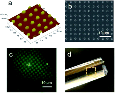
The topography of the micropatterned surface were examined using AFM and SEM. As shown in Fig. 8a, highly ordered patterns of PDMAEMA with 2 μm in diameter were observed to uniformly distribute on the Janus film. The micropatterns exhibit high fidelity to the template, forming cylindrical domains with an average height of ca. 250 nm. The patterns have high edge resolution with no debris between domains (Fig. 8b). To confirm the patterns in chemical functionality, 1% fluorescein disodium solution was placed on the film to stain the PDMAEMA hydrogel domains, owing to the electrostatic interaction between the positively charged tertiary amine and the negatively charged fluorescein.42,43 Fig. 8c shows the selectively stained patterns with green fluorescence on the hydrogel domains, while the rest of the surface was not stained by fluorescein.
The patterned Janus film can be easily transferred onto planar or curved surfaces by leveraging the asymmetric response of top and bottom surfaces to humidity change.11 Upon immersing in water, the bottom surface of the Janus film absorbs more water and expands. When attached onto the transferred surface, the bottom surface de-swells and shrinks with the decrease of humidity, resulting in good adhesion to the transferred substrate. Here we used a glass rod as an exemplary curved substrate. After drying in the air, the micropatterned film was observed to tightly adhere to the glass rod without forming any wrinkles, as seen in Fig. 8d.
Conclusion
We synthesized Janus polymer thin films using a single-step, vapor-based approach. Polymer layers with distinct compositions, including hydrogel, perfluoroalkyl polymer, and a highly crosslinked bulk, were incorporated into the film with covalent linkages formed between layers. Owing to the sandwich structure, the Janus film demonstrated asymmetric wetting behavior on the two surfaces of the film, while retaining the film integrity and mechanical robustness. The highly swellable hydrogel layer enables self-exfoliation of the Janus film without the aid of any sacrificial layer. The resulting films have relatively smooth surface morphology and high transparency towards visible light. The Janus film can be micropatterned with high resolution using the same vapor deposition and transferred onto nonplanar substrates. The vapor-based method demonstrated the capability to incorporate desired components into thin films for excellent overall performance.Acknowledgements
We are grateful for the support from the CAREER Award of National Science Foundation (CMMI 1056074). Y. Y. acknowledges the support from the National Natural Science Foundation of China (51403109), Natural Science Foundation of Ningbo (2015A610018), and the K. C. Wong Magna Fund in Ningbo University. We thank Dr Fang Liu for the help in nanoindentation experiments. We also thank the Oklahoma State University Microscopy Laboratory for the SEM and AFM experiments.References
- X. Tian, H. Jin, J. Sainio, R. H. A. Ras and O. Ikkala, Adv. Funct. Mater., 2014, 24, 6023–6028 CrossRef CAS.
- W. Zhang, Z. Shi, F. Zhang, X. Liu, J. Jin and L. Jiang, Adv. Mater., 2013, 25, 2071–2076 CrossRef CAS PubMed.
- D. Liang, Z. Lu, H. Yang, J. Gao and R. Chen, ACS Appl. Mater. Interfaces, 2016, 8, 3958–3968 CAS.
- L. Shen, B. Wang, J. Wang, J. Fu, C. Picart and J. Ji, ACS Appl. Mater. Interfaces, 2012, 4, 4476–4483 CAS.
- S. Yongli, L. Yue, W. Jianming, W. Weiguo, D. Anjie and Z. Jianhua, J. Biomater. Sci., Polym. Ed., 2014, 25, 713–728 CrossRef PubMed.
- B. B. Yue, B. W. Zhang, J. C. You, Y. J. Li, L. F. Li and J. Y. Li, RSC Adv., 2016, 6, 17215–17221 RSC.
- P. Xiao, C. Wan, J. Gu, Z. Liu, Y. Men, Y. Huang, J. Zhang, L. Zhu and T. Chen, Adv. Funct. Mater., 2015, 25, 2428–2435 CrossRef CAS.
- Q. Cheng, M. Li, Y. Zheng, B. Su, S. Wang and L. Jiang, Soft Matter, 2011, 7, 5948–5951 RSC.
- S. Abraham, G. B. Ma and C. D. Montemagno, Adv. Mater. Interfaces, 2016, 3, 1600445 CrossRef.
- L. Zhang, P. Xiao, W. Lu, J. W. Zhang, J. C. Gu, Y. J. Huang and T. Chen, Adv. Mater. Interfaces, 2016, 3, 1600170 CrossRef.
- L. Shen, J. Fu, K. Fu, C. Picart and J. Ji, Langmuir, 2010, 26, 16634–16637 CrossRef CAS PubMed.
- Y. B. Li, L. L. Song and Y. S. Qiao, RSC Adv., 2014, 4, 57611–57614 RSC.
- S. Hong, C. F. Schaber, K. Dening, E. Appel, S. N. Gorb and H. Lee, Adv. Mater., 2014, 26, 7581–7587 CrossRef CAS PubMed.
- J. Song, H. Liu, M. Wan, Y. Zhu and L. Jiang, J. Mater. Chem. A, 2013, 1, 1740–1744 CAS.
- H. Zhang, R. Hao, J. K. Jackson, M. Chiao and H. Yu, Chem. Commun., 2014, 50, 14843–14846 RSC.
- Y. Mao and K. K. Gleason, Langmuir, 2004, 20, 2484–2488 CrossRef CAS PubMed.
- K. K. S. Lau and K. K. Gleason, Adv. Mater., 2006, 18, 1972–1976 CrossRef CAS.
- Y. M. Ye, Q. Song and Y. Mao, J. Mater. Chem., 2011, 21, 13188–13194 RSC.
- H. Sojoudi, G. H. McKinley and K. K. Gleason, Mater. Horiz., 2015, 2, 91–99 RSC.
- Y. M. Ye, Q. Song and Y. Mao, J. Mater. Chem., 2011, 21, 257–262 RSC.
- W. E. Tenhaeff and K. K. Gleason, Adv. Funct. Mater., 2008, 18, 979–992 CrossRef CAS.
- Y. M. Ye and Y. Mao, J. Mater. Chem., 2011, 21, 7946–7952 RSC.
- Y. Ma, J. Sun and J. Shen, Chem. Mater., 2007, 19, 5058–5062 CrossRef CAS.
- J. Sun, C. Su, X. Zhang, W. Yin, J. Xu and S. Yang, Langmuir, 2015, 31, 5147–5154 CrossRef CAS PubMed.
- A. Zhuk, S. Pavlukhina and S. A. Sukhishvili, Langmuir, 2009, 25, 14025–14029 CrossRef CAS PubMed.
- M. Gupta and K. K. Gleason, Langmuir, 2006, 22, 10047–10052 CrossRef CAS PubMed.
- S. H. Baxamusa and K. K. Gleason, Adv. Funct. Mater., 2009, 19, 3489–3496 CrossRef CAS.
- Y. Yoo, J. B. You, W. Choi and S. G. Im, Polym. Chem., 2013, 4, 1664–1671 RSC.
- M. M. Kulkarni, R. Bandyopadhyaya and A. Sharma, J. Mater. Chem., 2008, 18, 1021–1028 RSC.
- Y. M. Ye, Y. Mao, F. Wang, H. B. Lu, L. T. Qu and L. M. Dai, J. Mater. Chem., 2011, 21, 837–842 RSC.
- D. Anton, Adv. Mater., 1998, 10, 1197–1205 CrossRef CAS.
- J. Wang, F. G. Shi, T. G. Nieh, B. Zhao, M. R. Brongo, S. Qu and T. Rosenmayer, Scr. Mater., 2000, 42, 687–694 CrossRef CAS.
- Y. Mao and K. K. Gleason, Macromolecules, 2006, 39, 3895–3900 CrossRef CAS.
- S. S. Ono and G. Decher, Nano Lett., 2006, 6, 592–598 CrossRef CAS PubMed.
- Q. Zhao, J. Qian, Q. An and B. Du, J. Mater. Chem., 2009, 19, 8448–8455 RSC.
- S. G. Lee, J. S. Lee, J. W. Ha, I. J. Park, S. B. Lee and J. D. Lee, J. Appl. Polym. Sci., 2009, 114, 3331–3337 CrossRef CAS.
- P. C. DeMuth, X. F. Su, R. E. Samuel, P. T. Hammond and D. J. Irvine, Adv. Mater., 2010, 22, 4851–4856 CrossRef CAS PubMed.
- P. Xiao, J. C. Gu, J. He, S. Wang, J. W. Zhang, Y. J. Huang, S. W. Kuo and T. Chen, J. Mater. Chem. C, 2016, 4, 9750–9755 RSC.
- N. Mari-Buye, S. O'Shaughnessy, C. Colominas, C. E. Semino, K. K. Gleason and S. Borros, Adv. Funct. Mater., 2009, 19, 1276–1286 CrossRef CAS PubMed.
- J. S. Katz, J. Doh and D. J. Irvine, Langmuir, 2006, 22, 353–359 CrossRef CAS PubMed.
- W. E. Tenhaeff, L. D. McIntosh and K. K. Gleason, Adv. Funct. Mater., 2010, 20, 1144–1151 CrossRef CAS.
- R. Kugler, O. Bouloussa and F. Rondelez, Microbiology, 2005, 151, 1341–1348 CrossRef CAS PubMed.
- N. Sahiner and M. Singh, Polymer, 2007, 48, 2827–2834 CrossRef CAS.
Footnote |
| † Electronic supplementary information (ESI) available. See DOI: 10.1039/c7ra03386a |
| This journal is © The Royal Society of Chemistry 2017 |

