 Open Access Article
Creative Commons Attribution 3.0 Unported Licence
Tuning the electronic and magnetic properties of penta-graphene using a hydrogen atom: a theoretical study†
Lin-Lin Liuab,
Ying Wangab,
Chun-Ping Chenab,
Hong-Xia Yuab,
Lu-Si Zhaoab and
Xiao-Chun Wang *ab
*ab
aInstitute of Atomic and Molecular Physics, Jilin University, Changchun, 130012, China. E-mail: wangxiaochun@jlu.edu.cn
bJilin Provincial Key Laboratory of Applied Atomic and Molecular Spectroscopy, Jilin University, Changchun, 130012, China
First published on 16th August 2017
Abstract
Herein, an isolated hydrogen atom absorbed on penta-graphene (PG) was predicted to induce magnetic moments and tune the electronic properties of penta-graphene and was systematically studied using first-principles calculations. The adsorption energy and formation energy calculations suggest that magnetic penta-graphene (M-PG) and weak magnetic penta-graphene (WM-PG) of hydrogen-absorbed PG systems are energetically the most favorable states among the possible hydrogen-absorbed configurations. The hydrogen atom adsorbed on the PG sheet can effectively tune the electronic properties of PG and change it from a semiconductor to half-metallic. In the M-PG system, this spin-polarized state is essentially localized on the three-fold coordinated C atoms in the first layer opposite to that where the hydrogen atom is chemisorbed. Through changing the bond angle and bond length of the adsorbed hydrogen atom on the PG system, we can remarkably increase the magnetic moment of the hydrogen-absorbed PG system by 137 times. This would allow us to design a magnetic nanoswitch to manipulate the magnetic state of PG. We also obtained the scanning tunneling microscopy (STM) images for future experimental identification. Our findings show that the hydrogen atom absorbed on the PG system will have exciting applications in magnetic storage technology and next-generation electronic and spintronic nanodevices.
1. Introduction
Currently, two-dimensional (2D) atomic-layer-based materials are being widely studied due to their atomic scale thickness and unique electronic and magnetic properties.1–3 As carbon is durable, light, and abundant, carbon-based magnets are expected to be more stable, versatile, and cheaper than the current transition-metal-based magnets. Contrary to most carbon allotropes with hexagonal building blocks, penta-graphene (PG) is exclusively composed of carbon pentagons. It is predicted that penta-graphene can withstand temperatures as high as 1000 K, has an unusual negative Poisson's ratio and ultrahigh ideal strength, outperforming graphene, and possesses an intrinsic quasi-direct band gap as large as 3.25 eV.4 Due to these superior properties, penta-graphene is anticipated to be a potential candidate for broad applications in nanoelectronics, nanomechanics, optoelectronics, and photovoltaics. Furthermore, both the mechanical and electronic properties of PG sheets can be refined via surface functionalization. H or F sp3 functionalization,5,6 transition metals,7,8 and strain9 can be sources of magnetism via the generation of dangling bond (DB) states. Recent theoretical investigations have revealed that hydrogenation can effectively tune the electronic and mechanical properties of penta-graphene.10 In addition, the electronic structures of the hydrogenated group IV monolayers are found to be topologically trivial.11 Isolated hydrogen atoms absorbed on graphene have been predicted to induce magnetic moments.1 J. Zhou et al. have theoretically demonstrated that it is possible to introduce ferromagnetism into graphene via surface modification using hydrogenation.12 Thus, we have carried out an in-depth study of hydrogen absorbed on a penta-graphene system.In this study, using a first-principles theory, we investigated isolated hydrogen atoms absorbed on penta-graphene (PG), which was predicted to induce magnetic moments and tune the electronic property. We defined the two favorable states of isolated hydrogen atom absorbed on PG as the magnetic penta-graphene (M-PG) and the weak magnetic penta-graphene (WM-PG). A new magnetic switch based on on-site proton transfer on the PG system was designed herein. We have also defined the on-site proton transfer as follows: the proton, which is located at the same site of the substrate after transfer, transfers to the other state only with different bond lengths and angles between the proton and the substrate. Although the abovementioned on-site proton transfer is quite different from the well-known intermolecular proton transfer and intramolecular proton transfer, it can also obviously change the properties of the system. First, both the binding energy and the formation energy are calculated to characterize the stability of the systems. The on-site proton transfer on the PG system not only changes the electronic band structures, but also changes the magnetic properties of the system. To gain more insight into the electronic structure of the M-PG and WM-PG systems, we calculated the electronic band structures and the spin-polarized local DOS (LDOS). We also calculated the three-dimensional spin polarized charge density to show the magnetic property characteristics of the systems. The charge density difference and Bader charge analyses can help to predict the electron transfer between the H atom and the PG sheet. The study presented herein suggests that the hydrogen-absorbed PG system can be a promising magnetic nanoswitch. Scanning tunneling microscopy (STM) images are demonstrated to reveal the relationship between the configurations of atoms and spatial distributions of electronic states related to PG adsorbed by hydrogen atom.
2. Computational methods
Spin-polarized density functional theory (DFT) calculations have been performed using the VASP code, which is based on the Perdew–Burke–Ernzerhof (PBE) version of the generalized gradient approximation13 and the projector augmented wave representation,14,15 including spin polarization corrections and dipole moment corrections.16,17 The dipole moment corrections were employed to account for the possible dipole moments in the hydrogen atom absorbed on the penta-graphene system.18,19 The plane-wave cut-off energy of 520 eV was used for all the elements in the calculations. PG is represented using a unit cell containing 6 atoms, with a (1 × 1) structure in the x–y plane and a vacuum layer of 15 Å in the direction perpendicular to the PG sheet to maintain low interactions between periodic images. The first Brillouin zone was sampled using the 11 × 11 × 1 Monkhorst–Pack k-point mesh; Gaussian smearing with a width of σ = 0.02 eV was used in all the calculations. In the energy minimization, we allowed all atoms in the slab to fully relax. Energy convergence was reached when the forces on the relaxed atoms were less than 0.02 eV Å−1.For the calculation of the STM images, the Tersoff–Hamann approximation was used.20 Although it is expressed in a simple form, the method is widely used and well known to be valid for many systems.21–23 In this system, the tunneling current is proportional to the surface local density of states (LDOS) at the tip position integrated over an energy range restricted by the applied bias voltage. Hence, the STM images are generated from the isosurface of the spatial distribution formed by the integration of the LDOS over the energy range from the Fermi energy EFermi to EFermi − eV with an applied voltage V, i.e.,  . Thereby, the calculated STM images should correspond to experimental constant-current images.
3. Results and discussion
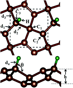
Before discussing the hydrogen atom absorbed on the PG system, we have demonstrated the optimized pristine PG sheet. Unlike graphene where all carbon atoms are sp2-hybridized, there are two chemically nonequivalent carbon atoms in PG. The unit cell contains two four-fold coordinated and four three-fold coordinated carbon atoms. For the convenience of discussion, we grouped the four-fold and three-fold coordinated carbon atoms of the pristine PG sheet as C1 and C2, respectively, as shown in Fig. 1. Herein, the calculated lattice constant of the pristine PG sheet is 3.64 Å, which is in good agreement with the theoretical value of 3.64 Å;4 this indicates the accuracy of our computational approaches.We then focused on the hydrogen atom absorbed on the PG system. Due to the special atomic configuration, Xiaoyin Li et al. have found that only the three-fold coordinated carbon atoms can adsorb hydrogen atom to form the hydrogenated PG sheet.10 As shown in Fig. 1, after the hydrogen atom was absorbed on the PG sheet, one of the three-fold coordinated carbons became four-fold coordinated. Moreover, we grouped the three-fold coordinated carbon atoms of the hydrogen-absorbed PG sheet as C3 and labelled the three bonds associated with the C3 atom as d1, d2, and d3 (see Fig. 1).
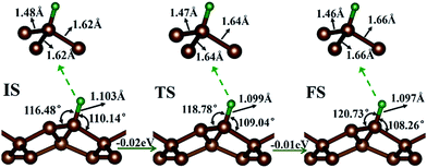
First, the hydrogen atom adsorbed on the PG sheet was studied. The optimized structure parameters of the M-PG and WM-PG systems are shown in Fig. 2. Compared to those for the PG sheet,4 the bond lengths of d1, d2, and d3 increased from 1.34 Å, 1.55 Å, and 1.55 Å to 1.48/1.46 Å, 1.62/1.66 Å, and 1.62/1.66 Å for the M-PG/WM-PG system, respectively, due to the adsorption of hydrogen; this implies the transformation of the double bond between C2 and C3 atoms into a single bond. In addition, the surface modification of PG elongates the bond length of d1, d2, and d3, thus partially releasing the strain stored in the pristine structure. According to these model studies,24–26 the changes in the bond lengths would lead to increased electron localization and splitting of the spin states. We defined h as the vertical coordinate difference of the top and bottom carbon layers (see Fig. 1). It can be observed that after the adsorption of hydrogen, the h increases to 1.402/1.399 Å of the M-PG/WM-PG system from 1.206 Å of the PG sheet. Through the on-site proton transfer on the PG sheet, the hydrogen adsorption position on PG did not change, but the angle (θ) significantly changed.
Both the binding energy EB and the formation energy EF were introduced to characterize the stability of the M-PG and WM-PG systems. Following the method reported in previous studies,27–29 the binding energy and the formation energy of the hydrogen atom absorbed on the PG system were calculated using the following formula:
| EB = EPG + EH − ETotal, | (1) |
| EF = ETotal − (EPG + EH2/2), | (2) |
Proton and H atom transfer mechanisms and dynamics represent one of the most fundamental processes involved in chemical reactions as well as in living systems.32–34 Through a spin-polarized calculation, we found that for the M-PG system, the total energy of antiferromagnetic (AFM) state was lower than that of the ferromagnetic (FM) state by 0.13 eV. For WM-PG, the total energy of the antiferromagnetic (AFM) state was lower than that of the ferromagnetic (FM) state by 0.02 eV, whereas the highest magnetic moment of a single atom was still very low (0.003 μB). The local configurations and the relevant structural parameters of each state for the whole on-site proton transfer on PG are displayed in Fig. 2. The M-PG and the WM-PG systems were selected as the IS and FS, respectively. At the TS, the lengths of d3 and d4 are shorter than those in the IS, and the θ also becomes smaller than that in the IS. However, the lengths of d1 and d2 are shorter than those in the IS. The reaction energy for this step is 0.02 eV, and the H binding energy for the IS with respect to the PG sheet is 2.77 eV, suggesting that the process should be energetically favorable. The obtained results show that the change in energy for the on-site proton transfer on PG is 0.03 eV. This energy change is caused by the electronic organization change associated with the atomic configuration change of the hydrogen atom adsorbed on the PG systems. UV-induced intramolecular proton transfer reactions have been observed and reported for numerous compounds.35
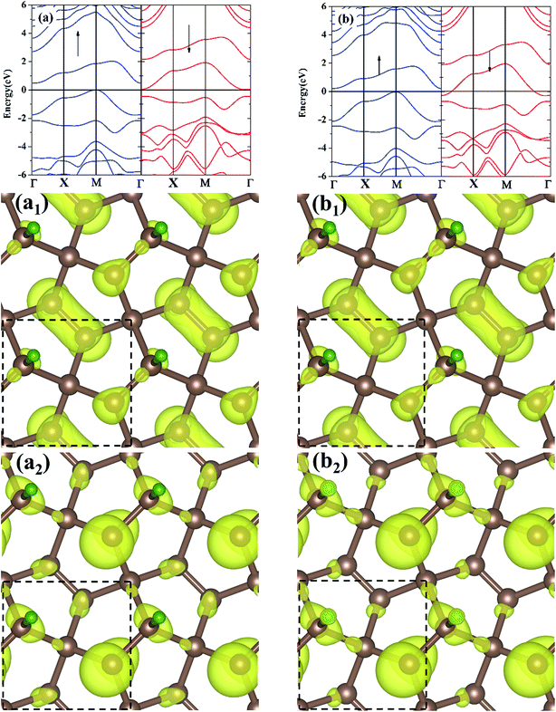
The electronic band structures for the M-PG and WM-PG systems are depicted in Fig. 3. The Fermi level is set at 0 eV. The electronic band structures of the M-PG and WM-PG systems are different. Interestingly, the M-PG system presents a half-metallic characteristic with the spin up channel being metallic and the spin down channel being semiconducting, as shown in Fig. 3(a). It can be seen that this M-PG system demonstrates magnetic half-metallicity with a total magnetic moment of 0.551 μB per unit cell. As plotted in Fig. 3(b), the paired spin-up channel (semiconducting) and the spin-down channel (metallic) of the band structures imply that the WM-PG system has very small magnetic characteristic with a total magnetic moment of 0.004 μB per unit cell. The valence band maximum (VBM) and conduction band minimum (CBM) are located at the same k points in the momentum space in the spin-up electronic band structure for the M-PG and WM-PG systems, but the CBM is located at 0.482 eV in the M-PG system, which is higher than 0.268 eV in the WM-PG system. Moreover, the on-site proton transfer has much effect on the band structures with the spin-polarized direction of the hydrogen-adsorbed PG system. The PG sheet possesses an intrinsic quasi-direct band gap as large as 3.25 eV.4 As a result of the H atom adsorption on the PG sheet, a new band originating from the H atom above the Fermi energy and the electronic bands of the PG sheet are modified, according to the electronic band structure of PG shown in Fig. S1 in ESI.† This can be attributed to the redistribution of charge density. The charge density distributions of the band edge states for the M-PG and WM-PG systems were calculated as well for comparison, and the results are presented in Fig. 3(a1), (a2), (b1), and (b2). There is more charge accumulation on the H atom of the WM-PG system (Fig. 3(b2)) than that in the M-PG system (Fig. 3(a2)). Compared to the band-decomposed charge density distribution of the PG sheet,4 the charge density distributions of the band edge states for the M-PG and WM-PG systems are different. This is because the adsorption of H atom locally removes the pz orbitals from the C3 atom; this results in full electron delocalization and changes the charge distribution of the C2–C3 bonds. Thus, the adsorption of H atom gives rise to disappearance of the band gap near the Fermi level for the M-PG and WM-PG systems.
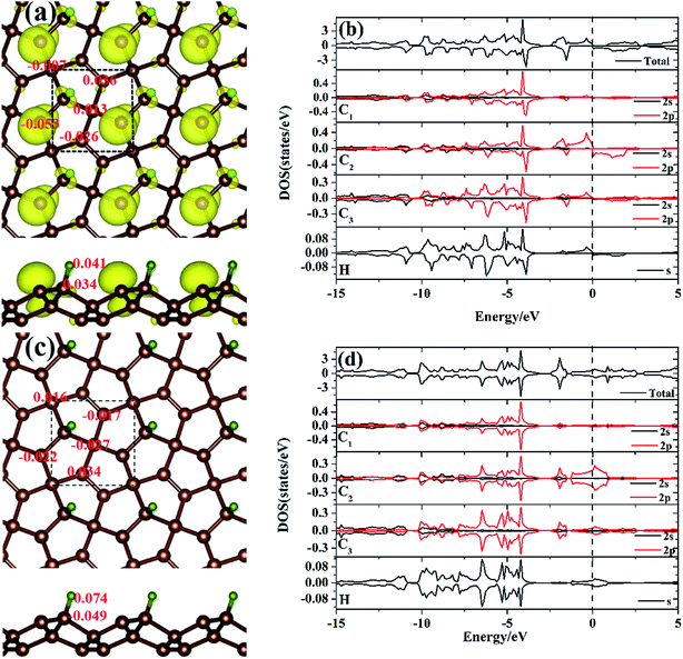
To gain more insight into the electronic structure of the hydrogen atom absorbed on the PG system, the spin-polarized local DOS (LDOS) of the M-PG and WM-PG systems were studied. The Fermi level is set at 0 eV, as shown in Fig. 4(b) and (d). We have found that the H atom is considered to form chemical bonds with the C3 atom in the two systems. The electronic structure of PG affected by H adsorption is reflected in the appearance of the electronic state at EF as compared to the LDOS of PG in Fig. S2 in ESI.† Therefore, it was instructive that we investigated the binding mechanisms in detail. First, the M-PG system is considered. The C atom (2s22p2) has four valence electrons; three of them form the C–C covalent σ bonds, whereas the fourth forms covalent σ bond with the H atom, which results in very high binding energy. Atomic H chemisorbs on the PG sheet on top of the C3 atom, changing the initial sp2 hybridization of carbon to essentially sp3 and effectively removing the corresponding pz orbital,36 creating a three-dimensional network of sp2 and sp3 carbon atoms. This approach demonstrates the possibility for the mixture of sp2–sp3 bonding and the magnetic coupling between π-electrons to induce magnetism into the PG sheet.37–40 As shown in Fig. 4(b), there are partially occupied C2 2p states near the Fermi level for the M-PG system. Moreover, the spin-up and spin-down DOS of the C1, C3, C2, and H orbitals and the total DOS are asymmetric (especially near the Fermi level); this leads to a magnetic moment of 0.551 μB per unit cell. Thus, our results stress the importance of hydrogen for the development of the magnetic state, and hydrogen can play a decisive role.41 The analysis of the spin density for the M-PG system shows that it is highly localized on the C2 atom. As shown in Fig. 4(a), the spin polarized charge distribution is in a wide area. Namely, besides the C2 atom, the C3 and H atoms also contribute to produce the magnetic properties.1 For the WM-PG system, the electronic structure is different. Through the on-site proton transfer, the proton H is still chemically adsorbed on the PG sheet on top of the same C3 atom with different bond lengths and angles. As shown in Fig. 4(d), the C1, C2, and C3 2p orbitals and H s orbitals significantly contribute to the total DOS between approximate −15 and 5 eV, and the presence of H s orbital peaks at the Fermi level further signifies the hybridization between the H atom and the C3 atom. The electronic states near the Fermi level not only originate from the sp2 hybridized C2 atoms, but also originate from the sp3 hybridized C3 atoms; this is further confirmed by calculating the band-decomposed charge density distributions (Fig. 3(b1) and (b2)). Unlike those in the M-PG system, the spin-up and spin-down DOS of the C1, C2, and C3 orbitals and the total DOS (Fig. 4(d)) were symmetric and induced very weak magnetic moments (0.004 μB per unit cell) because the coupling between the on-site proton transfer and the electron transfer resulted in the quenching of the spin magnetic moments; this was in good agreement with the analysis of the spin density for the WM-PG system (Fig. 4(c)). Because of the big difference in the C2 atom electronic configurations between the M-PG and WM-PG systems, the electrons in the C2 atom of the M-PG system are easier to be polarized. The hydrogen atoms with different on-site energy states on penta-graphene not only change the band structures but also change the magnetism of the carbon atoms in the PG. H. Gonzalez-Herrero's work shows that for large enough electron (hole) doping, the H-induced magnetic state changes to a single nonmagnetic state for the isolated hydrogen atoms absorbed on a graphene system.1 Contrary to H. Gonzalez-Herrero's work, herein, for PG with the hydrogen atoms absorbed on it, the mechanical movement of the absorbed hydrogen atoms can realize the switch between the magnetic state and the weak magnetic state without charge doping. This on-site proton transfer on the PG system could be used in a magnetic nanoswitch and magnetic storage technology.
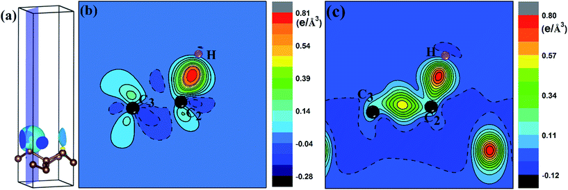
To quantify the charge distribution, we performed Bader charge analysis,42 which helped to show the charge transfer values for the H atom and the PG sheet, as depicted in Fig. 4(a) and (c). The charge density difference (Δρ(r)), which helps to predict the electron transfer between the H atom and the PG sheet, is defined as Δρ(r) = ρ(H + PG) − ρ(PG) − ρ(H), where ρ(H + PG) is the charge density of the M-PG or WM-PG system and ρ(PG) and ρ(H) are the charge densities of the independent PG sheet and the H atom, respectively, which are separately calculated using the same atomic coordinates and supercell as those in the corresponding M-PG or WM-PG system. The Bader charge analyses of the M-PG system (Fig. 4(c)) shows that C3 and H atoms are positively charged, and the two C atoms neighboring to the C3 atom are negatively charged, indicating that the unpaired electron on the H atom is transferred to the PG sheet and the C3–H bond is polarized; this is in good agreement with the electron density difference plotted in Fig. 5(b). Charge was obviously accumulated in the region between the C3 and H atoms, which indicates that the covalent bond formed between the adsorbed H and the PG sheet. This fact plays a role in the stabilization of the M-PG system, as discussed above. As for the WM-PG system, the Bader charge analyses (Fig. 4(a)) shows that two C atoms neighboring to the C3 atom are negatively charged. This can be attributed to the adsorption of the H atom. The negatively charged C3 atom pulls the positively charged H atom towards the surface. The H atom very strongly interacts with the C3 atom of the WM-PG system, and the C3 atom traps electrons from the H atom and become negatively charged. As shown in Fig. 5(c), there is not only a significant charge accumulation between the C2 and C3 atoms, but also a large charge accumulation between the C3 and H atoms. Thus, there are certain charge transfers from H atom to C3 atom area. Basically, the change trend of the charge transfer for the WM-PG system is in good agreement with that of the element electronegativity. According to the Pauling scale, the electronegativity of H and C is 2.20 and 2.55,43 respectively. According to the Bader analysis,44 the effective charges of H and C3 atoms are +0.074 e and −0.049 e, respectively. While shifting from the M-PG to WM-PG structure, the redistribution of charge density on PG is mainly induced by the on-site proton transfer. For both the M-PG and WM-PG systems, the charge of the chemisorbed hydrogen atom in PG is positive and less than +1 |e|, just as that of the hydrogen atom in the processes of intermolecular proton transfer or intramolecular proton transfer.
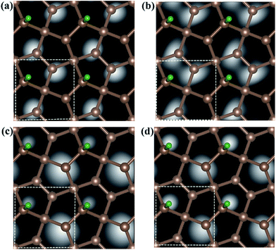
Fig. 6 shows the computed STM image of the M-PG (Fig. 6(a) and (c)) and WM-PG (Fig. 6(b) and (d)) systems at a bias voltage of −1 eV (valence band). The tip in the STM images, Fig. 6(a) and (b), is set to be approximately 1.5 Å lower than that of the third C layer in the PG sheet. The dark area in the STM image was located under the four-fold coordinated C atoms in the second layer of PG as if the C atom were absent because the four-fold coordinated C atoms layer were a little far from the point-like tip. Moreover, the three-fold coordinated C atoms in the third layer show bright spots because the charge spatial distribution of the C atoms near the Fermi level has a p-orbital character (Fig. 3(a1) and (b1)). The maximum height from the tip to the adsorbed H atom on the PG sheet in our calculations in the STM images is set to be about 0.5 Å, as shown in the Fig. 6(c) and (d). The STM images of the H atom adsorbed on the PG sheet show a bright spot centered on the H and C2 atoms due to the presence of the electronic states localized on the H and C2 atoms mainly in the valence band (Fig. 3(a1) and (b1)). The area of the bright spot of H atom in WM-PG is a little larger than that in the M-PG system. This fact indicates more charge at the H atom in the WM-PG system, which well conforms to the Bader charge analysis, as shown in Fig. 4(a) and (c).
4. Conclusions
In summary, an isolated hydrogen atom absorbed on PG sheet is predicted to induce magnetic moments and tune the electronic property. The larger binding energies and the negative formation energies suggest the stability of the M-PG and WM-PG systems. The hydrogen adsorbed on the PG system can effectively tune the electronic properties of the PG sheet and change it from a semiconductor to half-metallic. Atomic H chemisorbed on the PG sheet on top of the C3 atom induces a magnetic moment due to the mixture of sp2–sp3 bonding and the magnetic coupling between π-electrons in the M-PG system. Through the on-site proton transfer, we can remarkably increase the magnetic moment of the PG sheets by 137 times. The results reveal that the energy difference between the M-PG and WM-PG systems is merely 0.03 eV. We believe that this method might allow us to develop magnetic nanoswitches to manipulate the magnetic state of the PG sheets at the atomic-scale. We have also calculated the STM images for the adsorption of hydrogen on the PG sheet. The simulated STM images exhibit bright spots, depending strongly on the adsorbed hydrogen atom and the magnetic carbon atom. They are of great importance in future STM experiments for identifying the adsorption of hydrogen atom and the location of the magnetic carbon atom. Thus, our findings show that the ability to manipulate the magnetic state at the atomic-scale through on-site proton transfer on PG systems would have exciting applications in magnetic storage technology and next-generation electronic and spintronic nanodevices. Thus, we believe our design expands the diversity of PG applications.Conflicts of interest
There are no conflicts to declare.Acknowledgements
This work was supported by the National Natural Science Foundation of China (Grant No. 11474123) and the Natural Science Foundation of Jilin Province of China (Grant No. 20170101154JC). Lin-Lin Liu and Ying Wang contributed equally to this work.References
- H. Gonzalez-Herrero, J. M. Gomez-Rodriguez, P. Mallet, M. Moaied, J. Jose Palacios, C. Salgado, M. M. Ugeda, J.-Y. Veuillen, F. Yndurain and I. Brihuega, Science, 2016, 352, 437–441 CrossRef CAS PubMed.
- M. M. Monshi, S. M. Aghaei and I. Calizo, RSC Adv., 2017, 7, 18900–18908 RSC.
- M. D. Xie, C. G. Tan, P. Zhou, J. G. Lin and L. Z. Sun, RSC Adv., 2017, 7, 20116–20122 RSC.
- S. Zhang, J. Zhou, Q. Wang, X. Chen, Y. Kawazoe and P. Jena, Proc. Natl. Acad. Sci. U. S. A., 2015, 112, 2372–2377 CrossRef CAS PubMed.
- T. O. Wehling, M. I. Katsnelson and A. I. Lichtenstein, Phys. Rev. B: Condens. Matter Mater. Phys., 2009, 80, 085428 CrossRef.
- O. V. Yazyev, Phys. Rev. Lett., 2008, 101, 037203 CrossRef PubMed.
- E. J. G. Santos, D. Sanchez-Portal and A. Ayuela, Phys. Rev. B: Condens. Matter Mater. Phys., 2010, 81, 125433 CrossRef.
- H. Li, W. Chen, X. Shen, J. Liu, X. Huang and G. Yu, Phys. Chem. Chem. Phys., 2017, 19, 3694–3705 RSC.
- K. Tao, P. Liu, Q. Guo, L. Shen, D. Xue, O. P. Polyakov and V. S. Stepanyuk, Phys. Chem. Chem. Phys., 2017, 19, 4125–4130 RSC.
- X. Li, S. Zhang, F. Q. Wang, Y. Guo, J. Liu and Q. Wang, Phys. Chem. Chem. Phys., 2016, 18, 14191–14197 RSC.
- T.-C. Wang, C.-H. Hsu, Z.-Q. Huang, F.-C. Chuang, W.-S. Su and G.-Y. Guo, Sci. Rep., 2016, 6, 039083 CrossRef CAS PubMed.
- J. Zhou, Q. Wang, Q. Sun, X. S. Chen, Y. Kawazoe and P. Jena, Nano Lett., 2009, 9, 3867–3870 CrossRef CAS PubMed.
- J. P. Perdew and Y. Wang, Phys. Rev. B: Condens. Matter Mater. Phys., 1992, 45, 13244–13249 CrossRef.
- G. Kresse and J. Furthmüller, Phys. Rev. B: Condens. Matter Mater. Phys., 1996, 54, 11169–11186 CrossRef CAS.
- G. Kresse and D. Joubert, Phys. Rev. B: Condens. Matter Mater. Phys., 1999, 59, 1758–1775 CrossRef CAS.
- G. Makov and M. C. Payne, Phys. Rev. B: Condens. Matter Mater. Phys., 1995, 51, 4014–4022 CrossRef CAS.
- J. Neugebauer and M. Scheffler, Phys. Rev. B: Condens. Matter Mater. Phys., 1992, 46, 16067–16080 CrossRef CAS.
- F. Calle-Vallejo, J. Ignacio Martinez and J. Rossmeisl, Phys. Chem. Chem. Phys., 2011, 13, 15639–15643 RSC.
- Y. Ding and Y. Wang, J. Mater. Chem. C, 2016, 4, 1517–1526 RSC.
- J. Tersoff and D. R. Hamann, Phys. Rev. B: Condens. Matter Mater. Phys., 1985, 31, 805–813 CrossRef CAS.
- B. Zheng, P. Hermet and L. Henrard, ACS Nano, 2010, 4, 4165–4173 CrossRef CAS PubMed.
- H. Amara, S. Latil, V. Meunier, P. Lambin and J. C. Charlier, Phys. Rev. B: Condens. Matter Mater. Phys., 2007, 76, 115423 CrossRef.
- Y. Fujimoto and S. Saito, Phys. Rev. B: Condens. Matter Mater. Phys., 2011, 84, 245446 CrossRef.
- S. Okada, K. Nakada, K. Kuwabara, K. Daigoku and T. Kawai, Phys. Rev. B: Condens. Matter Mater. Phys., 2006, 74, 121412 CrossRef.
- J. Lahiri, Y. Lin, P. Bozkurt, I. I. Oleynik and M. Batzill, Nat. Nanotechnol., 2010, 5, 326–329 CrossRef CAS PubMed.
- L. Kou, C. Tang, W. Guo and C. Chen, ACS Nano, 2011, 5, 1012–1017 CrossRef CAS PubMed.
- L.-L. Liu, C.-P. Chen, L.-S. Zhao, Y. Wang and X.-C. Wang, Carbon, 2017, 115, 773–780 CrossRef CAS.
- D. Yi, L. Yang, S. Xie and A. Saxena, RSC Adv., 2015, 5, 20617–20622 RSC.
- X. Chen, L. Xu, L.-L. Liu, L.-S. Zhao, C.-P. Chen, Y. Zhang and X.-C. Wang, Appl. Surf. Sci., 2017, 396, 1020–1025 CrossRef CAS.
- M. Z. S. Flores, P. A. S. Autreto, S. B. Legoas and D. S. Galvao, Nanotechnology, 2009, 20, 465704 CrossRef CAS PubMed.
- D. Cortes-Arriagada, S. Gutierrez-Oliva, B. Herrera, K. Soto and A. Toro-Labbe, J. Chem. Phys., 2014, 141, 134701 CrossRef PubMed.
- Q. A. Cui and M. Karplus, J. Phys. Chem. B, 2002, 106, 7927–7947 CrossRef CAS.
- C. Tanner, C. Manca and S. Leutwyler, Science, 2003, 302, 1736–1739 CrossRef CAS PubMed.
- C. Fang, R. R. Frontiera, R. Tran and R. A. Mathies, Nature, 2009, 462, 200–204 CrossRef CAS PubMed.
- M. Pagacz-Kostrzewa, A. Bil and M. Wierzejewska, J. Photochem. Photobiol., A, 2017, 335, 124–129 CrossRef CAS.
- O. V. Yazyev and L. Helm, Phys. Rev. B: Condens. Matter Mater. Phys., 2007, 75, 125408 CrossRef.
- L. Jeloaica and V. Sidis, Chem. Phys. Lett., 1999, 300, 157–162 CrossRef CAS.
- D. Soriano, N. Leconte, P. Ordejon, J.-C. Charlier, J.-J. Palacios and S. Roche, Phys. Rev. Lett., 2011, 107, 016602 CrossRef PubMed.
- D. W. Boukhvalov, M. I. Katsnelson and A. I. Lichtenstein, Phys. Rev. B: Condens. Matter Mater. Phys., 2008, 77, 035427 CrossRef.
- P. Esquinazi, R. Hohne, K. H. Han, A. Setzer, D. Spemann and T. Butz, Carbon, 2004, 42, 1213–1218 CrossRef CAS.
- P. O. Lehtinen, A. S. Foster, Y. C. Ma, A. V. Krasheninnikov and R. M. Nieminen, Phys. Rev. Lett., 2004, 93, 187202 CrossRef CAS PubMed.
- W. Tang, E. Sanville and G. Henkelman, J. Phys.: Condens. Matter, 2009, 21, 084204 CrossRef CAS PubMed.
- A. L. Allred, J. Inorg. Nucl. Chem., 1961, 17, 215–221 CrossRef CAS.
- G. Henkelman, A. Arnaldsson and H. Jónsson, Comput. Mater. Sci., 2006, 36, 354–360 CrossRef.
Footnote |
| † Electronic supplementary information (ESI) available. See DOI: 10.1039/c7ra06956a |
| This journal is © The Royal Society of Chemistry 2017 |

