 Open Access Article
Creative Commons Attribution 3.0 Unported Licence
Microstructure and sintering behavior of low temperature cofired Li4/5Mg4/5Ti7/5O4 ceramics containing BaCu(B2O5) and TiO2 and their compatibility with a silver electrode†
Huanfu Zhou *,
Xianghu Tan,
Kangguo Wang,
Wendong Sun,
Hong Ruan and
Xiuli Chen
Guangxi Ministry-Province Jointly-Constructed Cultivation Base for State Key Laboratory of Processing for Non-ferrous Metal and Featured Materials, Guangxi Key Laboratory in Universities of Clean Metallurgy and Comprehensive Utilization for Non-ferrous Metals Resources, Collaborative Innovation Center for Exploration of Hidden Nonferrous Metal Deposits and Development of New Materials in Guangxi, School of Materials Science and Engineering, Guilin University of Technology, Guilin 541004, China. E-mail: zhouhuanfu@163.com
First published on 19th September 2017
Abstract
Li4/5Mg4/5Ti7/5O4 (LMT) ceramics were prepared via a solid-state reaction method. The LMT ceramics, sintered at 1100 °C, presented good microwave dielectric properties with εr = 22.8, Q × f = 100![[thin space (1/6-em)]](https://www.rsc.org/images/entities/char_2009.gif) 000 GHz and τf = −15.0 ppm °C−1. BaCu(B2O5) (BCB) was added to lower the sintering temperature of the ceramics. The addition of BCB reduced the sintering temperature, but slightly degraded the microwave dielectric properties of the LMT ceramics. The 0.97LMT–0.03BCB ceramic showed a low sintering temperature of 900 °C and good microwave dielectric properties with an appropriate εr of 20.9, high Q × f of 42
000 GHz and τf = −15.0 ppm °C−1. BaCu(B2O5) (BCB) was added to lower the sintering temperature of the ceramics. The addition of BCB reduced the sintering temperature, but slightly degraded the microwave dielectric properties of the LMT ceramics. The 0.97LMT–0.03BCB ceramic showed a low sintering temperature of 900 °C and good microwave dielectric properties with an appropriate εr of 20.9, high Q × f of 42![[thin space (1/6-em)]](https://www.rsc.org/images/entities/char_2009.gif) 104 GHz and negative τf of −24.0 ppm °C−1. TiO2 was added to improve the εr and adjust the τf value. The 0.85(0.97LMT–0.03BCB)–0.15TiO2 ceramic, sintered at 875 °C, showed good dielectric properties, with a high Q × f of 37
104 GHz and negative τf of −24.0 ppm °C−1. TiO2 was added to improve the εr and adjust the τf value. The 0.85(0.97LMT–0.03BCB)–0.15TiO2 ceramic, sintered at 875 °C, showed good dielectric properties, with a high Q × f of 37![[thin space (1/6-em)]](https://www.rsc.org/images/entities/char_2009.gif) 700 GHz, appropriate εr of 23.1 and near-zero τf of −5.9 ppm °C−1. Obviously, the 0.85(0.97LMT–0.03BCB)–0.15TiO2 ceramic is a good candidate for low temperature co-fired ceramic devices.
700 GHz, appropriate εr of 23.1 and near-zero τf of −5.9 ppm °C−1. Obviously, the 0.85(0.97LMT–0.03BCB)–0.15TiO2 ceramic is a good candidate for low temperature co-fired ceramic devices.
1. Introduction
Recently, low temperature co-fired ceramic (LTCC) technology has been widely used in the large-scale integration of microwave dielectric devices.1–4 In LTCCs, the microwave dielectric materials must be sintered at a temperature below the melting point of Ag (961 °C). Furthermore, the materials should have excellent microwave dielectric properties (a high quality factor, an appropriate permittivity and a near-zero temperature coefficient of resonant frequency) and good chemical compatibility with Ag.5–8 A huge number of ceramics with the AB2O4 spinel structure have been reported to exhibit good microwave dielectric properties, such as Li2MgTi3O8,9 Mg2TiO410 and Li2MgTiO4.11 However, their high sintering temperatures have limited their further application to LTCC devices. Therefore, many researchers are trying to lower the sintering temperatures of microwave dielectric ceramics. Sintering aids, super-fine powders and low melting point materials have all been used to realize low temperature sintering of ceramics.12–14 The addition of sintering aids can degrade the microwave dielectric properties of the ceramics, but do not increase their production cost. Using super-fine powders increases the production cost, but does not decrease the performance. It is difficult to find a new low melting point material.In this paper, Li4/5Mg4/5Ti7/5O4 (LMT) spinel ceramics were designed to obtain new microwave dielectric materials with good properties. The phase composition, microstructure and microwave dielectric properties of Li4/5Mg4/5Ti7/5O4 (LMT) spinel ceramics were studied. LMT ceramics exhibit high sintering temperatures, which restrict their further application. In order to control the production cost, the method of adding sintering aids has been widely adopted to lower the sintering temperature of LMT ceramics. Zhou et al.15 reported that the addition of BaCu(B2O5) (BCB) could lower the sintering temperature of ceramics. Their Ba3Ti5Nb6O28 ceramic, containing 5.0 wt% BCB and sintered at 925 °C, exhibited good microwave dielectric properties of Q × f = 19![[thin space (1/6-em)]](https://www.rsc.org/images/entities/char_2009.gif) 191 GHz, εr = 38.2 and τf = 12 ppm °C−1. Therefore, in this study, BCB was added to LMT ceramics to lower their sintering temperatures, and the effects of BCB on the sintering temperature and microwave dielectric properties of the ceramics are discussed herein. Furthermore, TiO2 was added to the LMT ceramics to improve their permittivity and adjust the temperature coefficient of resonant frequency to near-zero. The effects of TiO2 addition on the phase composition and microwave dielectric properties of the LMT + BCB ceramics were also examined.
191 GHz, εr = 38.2 and τf = 12 ppm °C−1. Therefore, in this study, BCB was added to LMT ceramics to lower their sintering temperatures, and the effects of BCB on the sintering temperature and microwave dielectric properties of the ceramics are discussed herein. Furthermore, TiO2 was added to the LMT ceramics to improve their permittivity and adjust the temperature coefficient of resonant frequency to near-zero. The effects of TiO2 addition on the phase composition and microwave dielectric properties of the LMT + BCB ceramics were also examined.
2. Experimental procedure
LMT ceramics were prepared via a conventional solid-state reaction method using high purity powers of Li2CO3 (≥99%), MgO (≥99%) and TiO2 (≥99%). The raw materials were stoichiometrically weighed and ball milled with zirconia balls in alcohol medium for 4 h. The mixtures were then rapidly dried and calcined at 900 °C for 4 h. The high purity powders (≥99%) of Ba(OH)2·8H2O, CuO and H3BO3 were used to prepare the BCB powders. The powders were stoichiometrically weighed, mixed, dried and calcined at 800 °C for 4 h. The LMT powders were mixed with different amounts of BCB for 4 h, and then part of the 0.97LMT–0.03BCB powders were mixed with different levels of TiO2 for 4 h. The (1 − x)LMT–xBCB(0 ≤ x ≤ 0.04) and (1 − y)[0.97LMT–0.03BCB]–yTiO2 (0.05 ≤ y ≤ 0.20) powders were granulated with 5 wt% polyvinyl alcohol (PVA) and pressed into disks of 12 mm in diameter and 6 mm in thickness using a uniaxial pressure of ∼200 MPa. Finally, the disks were sintered in the temperature range of 825–1025 °C for 4 h.The crystalline phases of the samples were identified using X-ray diffraction (XRD) with Cu Kα radiation generated at 40 kV and 40 mA (Model X'Pert PRO, PANalytical, Almelo, Holland). The surface morphology of the ceramics was studied using scanning electron microscopy (SEM) (Model JSM6380-LV SEM, JEOL, Tokyo, Japan). The bulk density of the sintered ceramics was tested using the Archimedes method. Dielectric behaviors at microwave frequencies were measured using the TE01δ shielded cavity method on a Network Analyzer (Model N5230A, Agilent Co., CA, 10 MHz to 40 GHz). The temperature coefficients of resonant frequency (τf) were measured using the open cavity method with an invar cavity in a temperature chamber (DELTA9039, Delta Design, USA). The τf values were calculated using the following formula:
 | (1) |
3. Results and discussion
3.1 Phase structure and microwave dielectric properties of LMT ceramics
Fig. 1 presents the XRD patterns of the LMT ceramics sintered at different temperatures. It can be seen that all the observed peaks were indexed according to Li2MgTi3O8 (PDF: 00-048-0263). The reasons for this phenomenon are as follows. Firstly, LiMg1/2Ti3/2O4 and Mg2TiO4 might be formed according to the following reaction mechanism: 0.4Li2CO3 + 0.8MgO + 1.4TiO2 → 0.8LiMg1/2Ti3/2O4 + 0.4CO2 + 0.2Mg2TiO4. It is worth noting that the cation sizes of LiMg1/2Ti3/2O4 and Mg2TiO4 are similar, and the mismatch (∇r) was calculated as 1.2% (≤15%). Furthermore, LiMg1/2Ti3/2O4 and Mg2TiO4 had a similar structure (spinel structure).16,17 Therefore, 1/2Li,1/4Mg,1/4Ti could be replaced with Mg, and LMT solid solution might be formed according to the following reaction mechanism: 0.8LiMg1/2Ti3/2 + 0.2Mg2TiO4 → Li4/5Mg4/5Ti7/5O4. The SEM micrographs of the LMT ceramics are shown in Fig. S1.† With increasing the sintering temperature from 1050 °C to 1100 °C, the merging of the small grains gave rise to larger grains and eliminated the pores, leading to an increased average grain size and decreased porosity. By further increasing the sintering temperature, the average grain size increased, because grains continued to arise. On the other hand, the velocity of the grain boundary was too fast when the sintering temperature was too high, making the elimination of pores difficult,18,19 so the porosity increased. The change in porosity resulted in a change of the bulk density.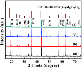 | ||
| Fig. 1 Room-temperature XRD patterns of the LMT ceramics sintered at (a) 1050 °C, (b) 1075 °C, (c) 1100 °C and (d) 1125 °C. | ||
Fig. 2 illustrates the bulk density (ρ), permittivity (εr) and quality factor (Q × f) of the LMT ceramics sintered at different temperatures. The ρ of the LMT ceramics firstly increased and then decreased with increasing the sintering temperature. The change of the εr and Q × f of the LMT ceramics as a function of the sintering temperature showed a trend similar to that of the ρ, showing that the relative density had a crucial effect on the εr and Q × f. The LMT ceramics sintered at 1100 °C possessed good microwave dielectric properties with a high Q × f of 100![[thin space (1/6-em)]](https://www.rsc.org/images/entities/char_2009.gif) 000 GHz, an appropriate εr of 22.8 and a negative τf of −15 ppm °C−1. The high sintering temperature limited the further application of LMT in LTCC devices, so BaCu(B2O5) (BCB) was chosen to reduce the sintering temperature of the ceramics.
000 GHz, an appropriate εr of 22.8 and a negative τf of −15 ppm °C−1. The high sintering temperature limited the further application of LMT in LTCC devices, so BaCu(B2O5) (BCB) was chosen to reduce the sintering temperature of the ceramics.
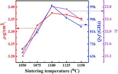 | ||
| Fig. 2 The bulk density (ρ), permittivity (εr) and Q × f values of the LMT ceramics as a function of their sintering temperatures. | ||
3.2 The effects of BCB addition on the sintering temperature and microwave dielectric properties of LMT ceramics
Fig. S2† shows the room-temperature XRD patterns of the (1 − x)LMT–xBCB (0.01 ≤ x ≤ 0.04) ceramics. The XRD patterns of all components were similar to that of LMT, and all observed peaks of (1 − x)LMT–xBCB were indexed according to Li2MgTi3O8 (PDF: 00-048-0263). Due to the low content of BCB in the (1 − x)LMT–xBCB ceramics, it could not be detected using XRD. Fig. S3† presents the SEM micrographs of the (1 − x)LMT–xBCB ceramics. The porosity increased and the average grain size decreased with increasing BCB content, which illustrates that the addition of BCB played a key role in changing the microstructure of the (1 − x)LMT–xBCB ceramics.The ρ, εr and Q × f of the (1 − x)LMT–xBCB ceramics as a function of the sintering temperature are illustrated in Fig. 3. The ρ, εr and Q × f of the (1 − x)LMT–xBCB ceramics first increased and then decreased with increasing sintering temperature. With increasing the BCB content, the sintering temperature of the (1 − x)LMT–xBCB ceramics gradually decreased, because BCB has a low sintering temperature (∼810 °C). With increasing the BCB content, the ρ of the (1 − x)LMT–xBCB ceramics slowly decreased, because the porosity of the (1 − x)LMT–xBCB ceramics increased. The phase composition has a great effect on the microwave dielectric properties of multiphase systems.20,21 Compared with LMT, BCB has relatively poor microwave dielectric properties, with εr of 7.4, Q × f of 50![[thin space (1/6-em)]](https://www.rsc.org/images/entities/char_2009.gif) 000 GHz and τf of −32 ppm °C−1.22 Therefore, the εr decreased from 21.1 to 20.9 and Q × f decreased from 58
000 GHz and τf of −32 ppm °C−1.22 Therefore, the εr decreased from 21.1 to 20.9 and Q × f decreased from 58![[thin space (1/6-em)]](https://www.rsc.org/images/entities/char_2009.gif) 807 GHz to 30
807 GHz to 30![[thin space (1/6-em)]](https://www.rsc.org/images/entities/char_2009.gif) 405 GHz. Table 1 shows that the τf decreased from −17.3 ppm °C−1 to −28.5 ppm °C−1 with increasing BCB content. The addition of BCB lowered the sintering temperature but also deteriorated the microwave dielectric properties of the ceramics. In particular, the 0.97LMT–0.03BCB ceramics showed a low sintering temperature of 900 °C and good microwave dielectric properties with an appropriate εr of 20.9, a high Q × f of 42
405 GHz. Table 1 shows that the τf decreased from −17.3 ppm °C−1 to −28.5 ppm °C−1 with increasing BCB content. The addition of BCB lowered the sintering temperature but also deteriorated the microwave dielectric properties of the ceramics. In particular, the 0.97LMT–0.03BCB ceramics showed a low sintering temperature of 900 °C and good microwave dielectric properties with an appropriate εr of 20.9, a high Q × f of 42![[thin space (1/6-em)]](https://www.rsc.org/images/entities/char_2009.gif) 104 GHz and a more negative τf of −24.0 ppm °C−1. In order to adjust the τf of the 0.97LMT–0.03BCB ceramic, (1 − y)[0.97LMT–0.03BCB]–yTiO2 (y = 0.05, 0.10, 0.15, 0.20) systems were designed.
104 GHz and a more negative τf of −24.0 ppm °C−1. In order to adjust the τf of the 0.97LMT–0.03BCB ceramic, (1 − y)[0.97LMT–0.03BCB]–yTiO2 (y = 0.05, 0.10, 0.15, 0.20) systems were designed.
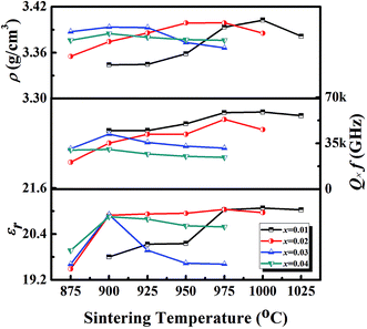 | ||
| Fig. 3 The bulk density (ρ), permittivity (εr) and Q × f values of the (1 − x)LMT–xBCB ceramics as a function of their sintering temperatures. | ||
| Condition | The optimum sintering temperature (°C) | τf (ppm °C−1) | |
|---|---|---|---|
| (1 − x)LMT–xBCB | x = 0 | 1100 | −15.0 |
| x = 0.01 | 1000 | −17.3 | |
| x = 0.02 | 975 | −20.5 | |
| x = 0.03 | 900 | −24.0 | |
| x = 0.04 | 900 | −28.5 | |
| (1 − y)[0.97LMT–0.03 BCB]–yTiO2 | y = 0.05 | 875 | −21.1 |
| y = 0.10 | 875 | −9.6 | |
| y = 0.15 | 875 | −5.9 | |
| y = 0.20 | 900 | −15.0 | |
3.3 The effects of TiO2 addition on the sintering temperature and microwave dielectric properties of LMT + BCB ceramics
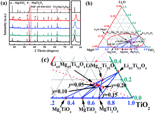
The room-temperature XRD patterns of the (1 − y)[0.97LMT–0.03BCB]–yTiO2 (y = 0.05, 0.10, 0.15, 0.20) ceramics are shown in Fig. 4(a). When y = 0.05–0.15, all XRD patterns agreed well with those of Li2MgTi3O8 (PDF: 00-048-0263) and MgTiO3 (PDF: 01-079-0831), and no other phases could be detected. When y = 0.05, the composition was (1 − z)LiMg1/2Ti3/2O4–zMg2TiO4 as a solid solution and MgTiO3 might be formed according to the following reaction mechanism: Mg2TiO4 + TiO2 → 2MgTiO3. When y = 0.10 or 0.15, Mg2TiO4 disappeared and Li4/3Ti5/3O4 appeared. LiMg1/2Ti3/2O4 and Li4/3Ti5/3O4 had similar crystal structures and ionic radii, so these compounds could form solid solutions. The composition was (1 − m)LiMg1/2Ti3/2O4–mLi4/3Ti5/3O4 as a solid solution. When y = 0.20, the diffraction peak of the MgTi2O5 (PDF: 00-020-0694) phase at lower angle regions of 20–30° was observed, due to the addition of excessive TiO2. MgTi2O5 may be formed according to the following reaction mechanism: MgTiO3 + TiO2 → MgTi2O5.Fig. 4(b) and (c) show the ternary phase diagrams of the Li2O–MgO–TiO2 systems and the enlarged patterns of the Mg2TiO4–MgTi2O5–Li4/3Ti5/3O4 concentration triangle, respectively. The ternary phase diagrams were used to identify the change in phase composition. The group point moved along the red line, dashed to the TiO2 point with increasing TiO2 content. When y = 0 or 0.05, the group point was located in the MgTiO3–LiMg1/2Ti3/2O4–Mg2TiO4 concentration triangle. With increasing y value, the group point is far away from the Mg2TiO4 and LiMg1/2Ti3/2O4 points but closer to the MgTiO3 point, indicating that the relative content of Mg2TiO4 and LiMg1/2Ti3/2O4 decreased, but the relative content of MgTiO3 increased. Furthermore, compared with the Mg2TiO4 point, the group point was closer to the LiMg1/2Ti3/2O4 point, which indicates that the relative content of Mg2TiO4 decreased in (1 − z)LiMg1/2Ti3/2O4–zMg2TiO4. Because the relative content of Mg2TiO4, with a large ionic radius, decreased in (1 − z)LiMg1/2Ti3/2O4–zMg2TiO4, the unit cell parameters of (1 − z)LiMg1/2Ti3/2O4–zMg2TiO4 decreased. When y = 0.10 and 0.15, the group point was located in the MgTiO3–LiMg1/2Ti3/2O4–Li4/3Ti5/3O4 concentration triangle. With increasing y value, the group point is far away from the LiMg1/2Ti3/2O4 point but closer to the Li4/3Ti5/3O4 point and MgTiO3 point, indicating that the relative content of LiMg1/2Ti3/2O4 decreased, but the relative content of MgTiO3 and Li4/3Ti5/3O4 increased. Compared with the LiMg1/2Ti3/2O4 point, the group point was closer to the Li4/3Ti5/3O4 point. When y = 0.20, the group point was located in the LiMg1/2Ti3/2O4–Li4/3Ti5/3O4–MgTi2O5–MgTiO3 concentration quadrilateral, implying the formation of MgTi2O5. Furthermore, the group point continued to approach the Li4/3Ti5/3O4 point for the LiMg1/2Ti3/2O4–Li4/3Ti5/3O4 line. Because the relative content of Li4/3Ti5/3O4, with a small ionic radius, increased in (1 − m)LiMg1/2Ti3/2O4–mLi4/3Ti5/3O4, the unit cell parameters of (1 − m)LiMg1/2Ti3/2O4–mLi4/3Ti5/3O4 decreased. Thus, LiMg1/2Ti3/2O4 peaks shifted to high angles, as shown in Fig. 4(a).
The SEM micrographs of the (1 − y)[0.97LMT–0.03BCB]–yTiO2 (y = 0.05, 0.10, 0.15, 0.20) ceramics are given in Fig. S4.† Compared with the undoped-TiO2 0.97LMT–0.03BCB ceramic, the average grain size of the 0.95[0.97LMT–0.03BCB]–0.05TiO2 ceramic was decreased, because the phase composition had changed as follows: [BCB and LMT solid solutions, y = 0] → [BCB, (1 − z)LiMg1/2Ti3/2O4–zMg2TiO4 solid solution and MgTiO3, y = 0.05]. With increasing the amount of TiO2 added from 0.05 to 0.20, the phase composition changed as follows: [BCB, (1 − z)LiMg1/2Ti3/2O4–zMg2TiO4 solid solution and MgTiO3, y = 0.05] → [BCB, (1 − m)LiMg1/2Ti3/2O4–mLi4/3Ti5/3O4 solid solution and MgTiO3, y = 0.10 and 0.15] → [BCB, (1 − m)LiMg1/2Ti3/2O4–mLi4/3Ti5/3O4 solid solution, MgTiO3 and MgTi2O5, y = 0.20]. The average grain size of (1 − y)[0.97LMT–0.03BCB]–yTiO2 gradually increased, but the porosity of the ceramics first decreased and then increased. Overall, the density of the ceramics increased first and then decreased. Furthermore, the EDS analysis of the 0.85[0.97LMT–0.03BCB]–0.15TiO2 ceramic is inserted in Fig. S4.† For “grain I”, the atomic number ratio of Mg to Ti is close to 1![[thin space (1/6-em)]](https://www.rsc.org/images/entities/char_2009.gif) :
:![[thin space (1/6-em)]](https://www.rsc.org/images/entities/char_2009.gif) 4, so “grain I” is the (1 − m)LiMg1/2Ti3/2O4–mLi4/3Ti5/3O4 solid solution. For “grain II”, the atomic number ratio of Mg to Ti is close to 1
4, so “grain I” is the (1 − m)LiMg1/2Ti3/2O4–mLi4/3Ti5/3O4 solid solution. For “grain II”, the atomic number ratio of Mg to Ti is close to 1![[thin space (1/6-em)]](https://www.rsc.org/images/entities/char_2009.gif) :
:![[thin space (1/6-em)]](https://www.rsc.org/images/entities/char_2009.gif) 1, so “grain II” is MgTiO3. BCB grains could not be found due to the low content of BCB.
1, so “grain II” is MgTiO3. BCB grains could not be found due to the low content of BCB.
The ρ, εr and Q anf of the (1 − y)[0.97LMT–0.03BCB]–yTiO2 ceramic as a function of the sintering temperature are demonstrated in Fig. 5. With increasing the sintering temperature, the ρ, εr and Q × f of the (1 − y)[0.97LMT–0.03BCB]–yTiO2 ceramic presented a similar trend. When the TiO2 content was increased from 0 to 0.05, the phase composition changed from BCB and LMT solid solution to a BCB, (1 − z)LiMg1/2Ti3/2O4–zMg2TiO4 solid solution and MgTiO3, and the bulk density and microwave dielectric properties of ceramics changed as follows: (ρ ∼ 3.39 g cm−3, Q × f ∼ 42![[thin space (1/6-em)]](https://www.rsc.org/images/entities/char_2009.gif) 104 GHz, εr ∼ 20.9, and τf ∼ −24.0 ppm °C−1) → (ρ ∼ 3.41 g cm−3, Q × f ∼ 35
104 GHz, εr ∼ 20.9, and τf ∼ −24.0 ppm °C−1) → (ρ ∼ 3.41 g cm−3, Q × f ∼ 35![[thin space (1/6-em)]](https://www.rsc.org/images/entities/char_2009.gif) 300 GHz, εr ∼ 21.9, and τf ∼ −21.1 ppm °C−1). When the amount of TiO2 added was increased from 0.05 to 0.15, ρ and the Q × f increased because the porosity decreased. By further increasing the amount of TiO2 added to 0.20, ρ and Q × f decreased due to the existence of MgTi2O5 and the increase in porosity.
300 GHz, εr ∼ 21.9, and τf ∼ −21.1 ppm °C−1). When the amount of TiO2 added was increased from 0.05 to 0.15, ρ and the Q × f increased because the porosity decreased. By further increasing the amount of TiO2 added to 0.20, ρ and Q × f decreased due to the existence of MgTi2O5 and the increase in porosity.
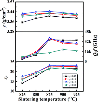 | ||
| Fig. 5 The bulk density (ρ), permittivity (εr) and Q × f values of the (1 − y)[0.97LMT–0.03BCB]–yTiO2 (y = 0.05, 0.10, 0.15, 0.20) ceramics as a function of their sintering temperatures. | ||
The εr of the multiphase system was related to the phase composition. However, the polarizability also played an important role in the εr of each phase. The polarizability (αz) of (1 − z)LiMg1/2Ti3/2O4–zMg2TiO4 (z decreased from 0.2 to 0) and (1 − m)LiMg1/2Ti3/2O4–mLi4/3Ti5/3O4 (m increased from 0 to positive value) was calculated as follows:
| α = xLi+ × αLi+ + xMg2+ × αMg2+ + xTi4+ × αTi4+ + xO2− × αO2− | (2) |
 | (3) |
The phase composition is the key factor affecting the τf in multiphase systems. The τf of (1 − z)LiMg1/2Ti3/2O4–zMg2TiO4 increased with a decrease in the z value and the τf of (1 − m)LiMg1/2Ti3/2O4–mLi4/3Ti5/3O4 increased with an increase in the m value, because Li4/3Ti5/3O4 exhibited a positive τf (15 ppm °C−1), LiMg1/2Ti3/2O4 showed a near-zero τf (3.2 ppm °C−1) and Mg2TiO4 presented a negative τf (−50 ppm °C−1).27,28 With increasing the y value from 0.05 to 0.15, the τf increased from −21.1 ppm °C−1 to −5.9 ppm °C−1, because the τf of (1 − z)LiMg1/2Ti3/2O4–zMg2TiO4 and (1 − m)LiMg1/2Ti3/2O4–mLi4/3Ti5/3O4 increased. However, the τf decreased to −15 ppm °C−1 due to the existence of MgTi2O5, which had a negative τf when y was increased to 0.20.29
The 0.85[0.97LMT–0.03BCB]–0.15TiO2 ceramic sintered at 875 °C exhibited good properties with a small ρ of 3.42 g cm−3, high Q × f of 37![[thin space (1/6-em)]](https://www.rsc.org/images/entities/char_2009.gif) 700 GHz, moderate εr of 23.1 and near-zero τf of −5.9 ppm °C−1, satisfying the requirements of microwave devices, such as a light weight, low loss, miniaturization and high stability. To identify whether the 0.85[0.97LMT–0.03BCB]–0.15TiO2 ceramic could be used in LTCC, the chemical compatibility between the 0.85[0.97LMT–0.03BCB]–0.15TiO2 ceramic and Ag powders was investigated. An XRD pattern and a backscattered electron image of 0.85[0.97LMT–0.03BCB]–0.15TiO2 with 20 wt% Ag powder sintered at 875 °C are displayed in Fig. 6. The results show that the 0.85[0.97LMT–0.03BCB]–0.15TiO2 ceramic did not react with the Ag powder. The 0.85[0.97LMT–0.03BCB]–0.15TiO2 ceramic show good chemical compatibility with Ag. The results indicate that the 0.85[0.97LMT–0.03BCB]–0.15TiO2 ceramic is a good commercial LTCC material.
700 GHz, moderate εr of 23.1 and near-zero τf of −5.9 ppm °C−1, satisfying the requirements of microwave devices, such as a light weight, low loss, miniaturization and high stability. To identify whether the 0.85[0.97LMT–0.03BCB]–0.15TiO2 ceramic could be used in LTCC, the chemical compatibility between the 0.85[0.97LMT–0.03BCB]–0.15TiO2 ceramic and Ag powders was investigated. An XRD pattern and a backscattered electron image of 0.85[0.97LMT–0.03BCB]–0.15TiO2 with 20 wt% Ag powder sintered at 875 °C are displayed in Fig. 6. The results show that the 0.85[0.97LMT–0.03BCB]–0.15TiO2 ceramic did not react with the Ag powder. The 0.85[0.97LMT–0.03BCB]–0.15TiO2 ceramic show good chemical compatibility with Ag. The results indicate that the 0.85[0.97LMT–0.03BCB]–0.15TiO2 ceramic is a good commercial LTCC material.
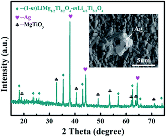 | ||
| Fig. 6 XRD pattern and backscattered electron image of 0.85[0.97LMT–0.03BCB]–0.15TiO2 with 20 wt% Ag powder sintered at 875 °C. | ||
4. Conclusion
LMT ceramics have been prepared using a solid-state reaction method and excellent microwave dielectric properties were obtained in ceramics sintered at 1100 °C. The addition of BCB could reduce the sintering temperature of the ceramics to 900 °C. TiO2 was introduced to improve the εr and τf values. The Q × f, εr and τf values firstly increased and then decreased with increasing the TiO2 content. The 0.85[0.97LMT–0.03BCB]–0.15TiO2 ceramic exhibited a low sintering temperature (∼875 °C), good microwave dielectric properties (Q × f = 37![[thin space (1/6-em)]](https://www.rsc.org/images/entities/char_2009.gif) 700 GHz, εr = 23.1 and τf = −5.9 ppm °C−1) and chemical compatibility with silver powder, indicating that it is a promising candidate material for LTCC devices.
700 GHz, εr = 23.1 and τf = −5.9 ppm °C−1) and chemical compatibility with silver powder, indicating that it is a promising candidate material for LTCC devices.
Conflicts of interest
There are no conflicts to declare.Acknowledgements
This work was supported by Natural Science Foundation of China (No. 11464009, 61761015, 11664008 and 11364012), Natural Science Foundation of Guangxi (No. 2015GXNSFDA139033), and Project of Outstanding Young Teachers' Training in Higher Education Institutions of Guangxi.References
- D. Zhou, W. B. Li, H. H. Xi, L. X. Pang and G. S. Pang, J. Mater. Chem. C, 2015, 3, 2582 RSC.
- K. C. Li, H. Wang and H. F. Zhou, Int. J. Appl. Ceram. Technol., 2010, 7, E144 CrossRef.
- W. Lei, W. Z. Lu and X. C. Wang, Ceram. Int., 2012, 38, 99 CrossRef CAS.
- H. L. Pan, Q. Q. Liu, Y. H. Zhang and H. T. Wu, RSC Adv., 2016, 6, 86889 RSC.
- H. Wu and E. S. Kim, RSC Adv., 2016, 6, 47443 RSC.
- J. R. Kim, D. W. Kim, H. S. Jung and K. S. Hong, J. Eur. Ceram. Soc., 2006, 26, 2105 CrossRef CAS.
- Y. G. Zhao and P. Zhang, RSC Adv., 2015, 5, 97746 RSC.
- X. Y. Du, H. Su, H. W. Zhang, X. T. Liu and X. L. Tang, RSC Adv., 2017, 7, 27415 RSC.
- G. G. Yao, P. Liu and H. W. Zhang, J. Mater. Sci.: Mater. Electron., 2013, 24, 1128 CrossRef CAS.
- C. L. Huang and S. S. Liu, J. Alloys Compd., 2009, 471, L9 CrossRef CAS.
- C. Pei, G. Yao, P. Liu and J. Zhou, Mater. Lett., 2016, 184, 57 CrossRef CAS.
- Z. Zhou, H. Su, X. Tang and H. Zhang, Ceram. Int., 2016, 42, 11161 CrossRef CAS.
- Z. H. Yao, H. X. Liu and Z. Y. Shen, Mater. Res. Bull., 2006, 41, 1972 CrossRef CAS.
- J. J. Bian, Q. Yu and J. J. He, J. Eur. Ceram. Soc., 2017, 37, 647 CrossRef CAS.
- H. F. Zhou, H. Wang, Y. H. Chen, K. C. Li and X. Yao, Mater. Chem. Phys., 2009, 113, 1 CrossRef CAS.
- J. B. Lim, K. H. Cho and S. Nahm, Mater. Res. Bull., 2006, 41, 1868 CrossRef CAS.
- X. Tang, H. Yang, Q. L. Zhang and J. H. Zhou, Ceram. Int., 2014, 40, 12875 CrossRef CAS.
- Z. Q. Yuan, B. Liu, X. Q. Liu and X. M. Chen, RSC Adv., 2016, 6, 96229 RSC.
- X. W. Jiang, L. Fang, H. C. Xiang and H. H. Guo, Ceram. Int., 2015, 41, 13878 CrossRef CAS.
- J. J. Bian, K. Yan and H. B. Gao, Mater. Chem. Phys., 2006, 96, 349 CrossRef CAS.
- S. Wu, K. Song, P. Liu, H. Lin and F. Zhang, J. Am. Ceram. Soc., 2015, 98, 1842 CrossRef CAS.
- M. H. Kim, J. B. Lim, J. C. Kim and S. Nahm, J. Am. Ceram. Soc., 2006, 89, 3124 CrossRef CAS.
- H. I. Hsiang and S. H. Chung, J. Alloys Compd., 2008, 465, 356 CrossRef CAS.
- R. D. Shannon, J. Appl. Phys., 1993, 73, 348 CrossRef CAS.
- Y. C. Chen, H. M. You and K. C. Chang, Ceram. Int., 2014, 41, 5257 CrossRef.
- H. L. Pan, Q. Q. Liu, Y. H. Zhang and H. T. Wu, RSC Adv., 2016, 6, 86889 RSC.
- R. K. Bhuyan, T. S. Kumar and D. Goswami, Mater. Sci. Eng., B, 2013, 178, 471 CrossRef CAS.
- W. Li, J. Alloys Compd., 2017, 701, 295 CrossRef CAS.
- V. M. Ferreira, F. Azough and R. Freer, J. Mater. Res., 1997, 12, 3293 CrossRef CAS.
Footnote |
| † Electronic supplementary information (ESI) available. See DOI: 10.1039/c7ra07203a |
| This journal is © The Royal Society of Chemistry 2017 |

