 Open Access Article
Creative Commons Attribution 3.0 Unported Licence
Bis-tridentate Ru(II) sensitizers with a spatially encumbered 2,6-dipyrazolylpyridine ancillary ligand for dye-sensitized solar cells†
Ting-Kuang Chang and
Yun Chi *
*
Department of Chemistry, Low Carbon Energy Research Center, National Tsing Hua University, Hsinchu 30013, Taiwan. E-mail: ychi@mx.nthu.edu.tw
First published on 30th August 2017
Abstract
Bis-tridentate Ru(II) sensitizers with a 4,4′,4′′-tricarboxy-2,2′:6′,2′′-terpyridine anchor (i.e. tctpy) and a 2,6-dipyrazolyl pyridine ancillary ligand with either 5-dodecylthien-2-yl or t-butyl substituents at the central pyridyl unit and four distinctive perfluoroalkyl fragments (e.g. CF3, C3F7, C5F11 and C7F15) at the terminal pyrazolyl sites were designed, synthesized and applied as sensitizers for the fabrication of dye-sensitized solar cells. All these sensitizers exhibited suitable optical properties and electrochemical characteristics. In addition, despite the TF-tBu series of sensitizers with t-butyl substituents showing a lowered absorption extinction coefficient vs. their 5-dodecylthien-2-yl substituted counterparts (i.e. TF-2′ series) in solution, their smaller molecular size allowed a larger dye loading on TiO2 photoanodes, which offsets the inferior optical response and makes them the better DSC sensitizers. After appropriate selection of C3F7 substituents, the sensitizer coded TF-tBu_C3F7 showed the highest overall efficiencies of JSC = 18.47 mA cm−2, VOC = 767 mV, FF = 0.71 and PCE = 10.05% under simulated one sun irradiation, due to the fine balance between dye loading and reduced charge recombination. The corresponding enlarged solar cell module with an active area of 11.2 cm2 also showed the best PCE of 7.55% under one sun irradiation with PCE reaching 12.70% under T5 lighting at 2400 lux.
1. Introduction
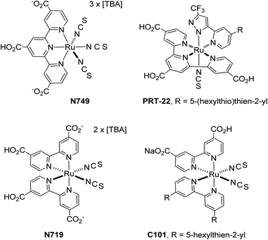
Dye sensitized solar cells (DSC) have attracted considerable research attention as a possible replacement for commercial silicon based photovoltaics due to the lower fabrication costs and versatility in making flexible devices.1–7 DSC are composed of three compartments: (i) a layer of TiO2 nanoparticles with the deposited light-harvesting sensitizers which enable injection of photoelectrons,8 (ii) an electrolyte containing a suitable redox couple (most commonly I3−/I−) for regeneration of the oxidized sensitizers,9 and (iii) a counter electrode (or cathode) to reduce the oxidized component of the electrolyte to complete the carrier flux.10 Sensitizers constitute one key challenge in the development of efficient and stable DSC devices. Despite having many adequate precedents, such as: Ru(II) thiocyanate and azolate complexes,11–14 zinc porphyrins,15–18 and even organic dyes with push–pull charge transfer characteristics,19–22 they are still not satisfactory because of the poor device longevity, particular they require introduction of a co-adsorbent to suppress aggregation of the sensitizers on the TiO2 surface for increasing the VOC.Amid various DSC sensitizers, Ru(II) complexes are probably the best design that showed better compromise between device efficiency and stability.23–25 They were reported to achieve high power conversion efficiency (PCE) of over 11.5% with the employment of sensitizers N749 (ref. 26 and 27) and PRT-22,28 independently. Both sensitizers possess 4,4′,4′′-tricarboxy-2,2′:6′,2′′-terpyridine anchoring chelate (i.e. tctpy) and at least one thiocyanate ancillary (cf. Scheme 1). Due to the possession of three carboxy anchors in tctpy chelate, these Ru(II) sensitizers have exhibited a further red-shifted absorption onsets versus the Ru(II) sensitizers with the alternative 4,4′-dicarboxy-2,2′-bipyridine anchor (i.e. dcbpy), as shown in N719, C101 and etc. Notably, DSC fabricated with the dcbpy based Ru(II) sensitizers are also capable to exhibit high PCE of ∼11.1%,29 but their relative performances are still inferior to that of tctpy based Ru(II) sensitizers due to the reduced π-conjugation of dcbpy that caused higher onset energy for light absorption.
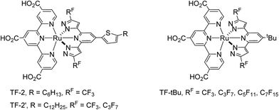
Furthermore, the performance of these Ru(II) based DSC devices, particularly the longevity, is known to depend on their intrinsic molecular structure, which can be improved by removal of thiocyanate ancillaries and replaced them with a dianionic tridentate ancillary in addition to the tctpy anchor. These so-called bis-tridentate sensitizers possess two tridentate chelates (one with carboxy-containing anchor),30–34 for which the dye molecules are expected to be more stable than those bearing monodentate thiocyanate35–37 and even the alternative Ru(II) sensitizers with tris-heteroleptic or tris-bidentate architecture,38–41 from the view point of entropy. In view of this, we proceed to optimize the TF-series of Ru(II) sensitizers, namely: TF-2, TF-2′ and TF-tBu by attachment of distinctive alkyl group (R = C6H13 and C12H25) and perfluoroalkyl group (RF = CF3, C3F7, C5F11 and C7F15) at the azolyl fragments of the 2,6-dipyrazolyl pyridine ancillary, for which the abbreviations TF-2, TF-2′ and TF-tBu stand for the bis-tridentate Ru(II) sensitizers substituted with 5-hexylthien-2-yl, 5-dodecylthien-2-yl and t-butyl fragment at the 4-position of central pyridyl unit of the 2,6-dipyrazolyl pyridine ancillary (cf. Scheme 2). Moreover, the TF-2′ is a modification of original TF-2, for which the 5-hexylthienyl group was judiciously substituted with dodecylthienyl group. This maneuver has effectively increased the solubility of sensitizers in dye solution, and afforded better processability and reproducibility in fabrication of solar cells.42,43 As for the class of TF-tBu sensitizers, the t-Bu substituent is known for its capability in suppressing intermolecular ππ stacking occurred between the planar chelate of sensitizers and preventing dye aggregation on the TiO2 surface,44–46 both would afford better DSC efficiency vs. those without alkyl substituents. In contrast, TF-2 and TF-2′ derivatives with the thien-2-yl fragment are notable for the enhanced optical response for the single molecule due to the extended π-conjugation and enlarged absorption extinction coefficient. Hence, understanding of these properties should be of valuable in designing better DSC sensitizers as well as associated devices.
2. Results and discussion
Synthesis and structural characterization
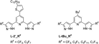
The 2,6-dipyrazolyl pyridine ancillaries, i.e. with either 5-dodecylthien-2-yl or t-butyl fragment at the 4-position of central pyridyl unit and various perfluoroalkyl groups at the pyrazolyl sites were synthesized for fine-tuning the UV-Vis absorption, physical and photovoltaic properties (Scheme 3). Chelate L-2 was obtained using literature method,47,48 while chelates L-2_C3F7 was synthesized using pentyl perfluorobutyrate instead of ethyl perfluorobutyrate. The employment of pentyl ester is for increasing the miscibility in reaction media; otherwise, serious foaming will take place to reduce the product yield. Similarly, the t-Bu substituted chelates, i.e. L-tBu_RF, RF = CF3, C3F7, C5F11 and C7F15, were obtained from 2,6-diacetyl-4-t-butyl pyridine using identical protocol. After then, the sequential reaction of RuCl3·3H2O with 4,4′,4′′-triethoxycarbonyl-2,2′:6′,2′′-terpyridine (tectpy), followed by treatment with 2,6-dipyrazolyl pyridine afforded the ethoxycarbonyl substituted Ru(II) intermediate complexes. After column chromatography on silica and recrystallization, they were hydrolysis in mixed acetone and 1 M NaOH(aq) to afford the final Ru(II) sensitizers TF-2′_RF and TF-tBu_RF, by precipitation upon acidification to pH = 3.Photophysical behaviors
The absorption and normalized emission spectra of these TF series of sensitizers were recorded in DMF at a concentration of 1 × 10⁻⁵ M, which are depicted in Fig. 1, while their numeric spectral and electrochemical data are summarized in Table 1. All TF sensitizers display a broadened absorption at the higher energy region around ∼325 nm, attributed to the intra-ligand ππ* transition. In addition, they showed two more, slightly lower energy absorptions in the regions 402–421 nm and 502–510 nm with sufficiently large extinction coefficient in the range of 1.2–2.0 × 10⁴ M−1 cm−1, respectively; together with the lowest energy metal-to-ligand charge transfer (MLCT) absorption extended down to ∼710 nm and beyond.45 Without doubt, the much red-shifted peak position and the higher extinction coefficient for both sensitizers TF-2′_CF3 and TF-2′_C3F7 are due to the greater π-conjugation of thienyl appendage on the 2,6-dipyrazolyl pyridine ancillary.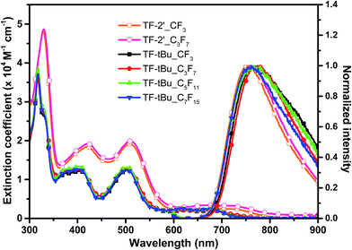 | ||
| Fig. 1 UV-Vis absorption and normalized emission spectra of the studied TF sensitizers in DMF solution. | ||
| Sensitizer | λmax [nm](ε × 103)a | λema [nm] | Eox (V) NHEb | E0–0c (eV) | Ered (V) NHEd |
|---|---|---|---|---|---|
| a Photophysical data were measured in DMF solution at 1 × 10⁻⁵ mol L−1.b Eox were measured in DMF with 0.1 M (nBu)4NPF6 as electrolyte. It was calibrated with FcH/FcH+ as internal reference and converted to NHE by addition of 0.63 V.c E0–0 was derived the intersection of the absorption and tangent of emission in DMF.d Ered was calculated according to equation Eox − E0–0. | |||||
| TF-2′_CF3 | 329(48), 421(18), 509(19), 654(2.5), 719(2.4) | 754 | 0.95 | 1.80 | −0.85 |
| TF-2′_C3F7 | 330(49), 421(19), 510(20), 656(3.4), 716(3.3) | 761 | 0.95 | 1.81 | −0.86 |
| TF-tBu_CF3 | 317(36), 404(12), 504(12), 621(2.1), 675(2.1) | 764 | 0.93 | 1.83 | −0.90 |
| TF-tBu_C3F7 | 317(36), 402(13), 503(13), 621(2.1), 675(2.2) | 770 | 0.93 | 1.86 | −0.93 |
| TF-tBu_C5F11 | 317(39), 402(13), 502(13), 619(2.6), 676(2.5) | 767 | 0.93 | 1.86 | −0.93 |
| TF-tBu_C7F15 | 317(37), 403(13), 502(13), 619(2.5), 676(2.5) | 763 | 0.93 | 1.86 | −0.93 |
Electrochemical properties
The ground and excited-state oxidation potentials (Eox and Ered) of these TF sensitizers are next estimated using cyclic voltammetry and the spectroscopic measurement. As shown in Table 1, all of the ground-state oxidation potentials 0.93–0.95 V (vs. normal hydrogen electrode, NHE) are more positive than that the I−/I3− redox couple (ca. 0.35 V vs. NHE), despite of having various fluoroalkyl appendage attached at the ancillary chelate. This observation confirms the existence of sufficient electrochemical driving force for regeneration of oxidized sensitizers. Moreover, the excited-state oxidation potentials of −0.90 to −0.93 V, which were estimated from the difference of Ered and the optical band gap, are also notably more negative than the conducting band potential (ca. −0.5 V vs. NHE) of nanocrystalline TiO2, confirming the occurrence of effective electron injection.Photovoltaic performances
For the device fabrication, the anode consisted of a 15 μm layer of 20 nm sized transparent TiO2 (anatase) nanoparticles and a second 5 μm layer of 400 nm sized scattering particles, both were deposited by screen printing to form a square with dimensions of 0.50 × 0.50 cm2. The TiO2 anode was immersed into either a 0.3 mM solution of selected sensitizer in a mixture of DMSO and ethanol (v/v, 1![[thin space (1/6-em)]](https://www.rsc.org/images/entities/char_2009.gif) :
:![[thin space (1/6-em)]](https://www.rsc.org/images/entities/char_2009.gif) 4) without co-adsorbent, or a solution of 0.3 mM of sensitizer in mixed ethanol and t-butanol (v/v, 1
4) without co-adsorbent, or a solution of 0.3 mM of sensitizer in mixed ethanol and t-butanol (v/v, 1![[thin space (1/6-em)]](https://www.rsc.org/images/entities/char_2009.gif) :
:![[thin space (1/6-em)]](https://www.rsc.org/images/entities/char_2009.gif) 1), along with 0.6 mM of tetra-butylammonium deoxycholate [TBA][DOC] as co-adsorbent, with an intention for boosting DSC efficiency.49 The employment of distinctive solvent mixture is intended for improving the solubility of co-adsorbent, while the typical dyeing process require approx. 18 hours to complete. Next, the counter electrodes were prepared from commercially available FTO glass (7 Ω/TEC7, 2.2 mm thick, Pilkington) and a solution of PVP capped platinum nanoclusters (PVP-Pt) via a so-called “two-step dip-coating” process, followed by a post thermal annealing at 325 °C for 10 min. The cells were assembled using a hot-melt Surlyn film (Meltonix 1170-25, 25 mm, Solaronix), and heated at 135 °C. Electrolyte contains 0.6 M 1,2-dimethyl-3-propylimidazolium iodide (DMPII), 0.1 M lithium iodide, 0.05 M iodine, and 0.5 M t-butylpyridine (tBP) in acetonitrile. This solution was injected into the assembled cell through a pre-drilled hole at the counter electrode.
1), along with 0.6 mM of tetra-butylammonium deoxycholate [TBA][DOC] as co-adsorbent, with an intention for boosting DSC efficiency.49 The employment of distinctive solvent mixture is intended for improving the solubility of co-adsorbent, while the typical dyeing process require approx. 18 hours to complete. Next, the counter electrodes were prepared from commercially available FTO glass (7 Ω/TEC7, 2.2 mm thick, Pilkington) and a solution of PVP capped platinum nanoclusters (PVP-Pt) via a so-called “two-step dip-coating” process, followed by a post thermal annealing at 325 °C for 10 min. The cells were assembled using a hot-melt Surlyn film (Meltonix 1170-25, 25 mm, Solaronix), and heated at 135 °C. Electrolyte contains 0.6 M 1,2-dimethyl-3-propylimidazolium iodide (DMPII), 0.1 M lithium iodide, 0.05 M iodine, and 0.5 M t-butylpyridine (tBP) in acetonitrile. This solution was injected into the assembled cell through a pre-drilled hole at the counter electrode.
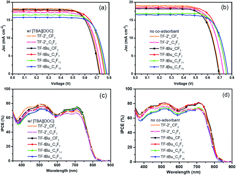
Fig. 2(a) and (b) depicted the photocurrent–voltage response of the DSC devices fabricated using aforementioned dye solution, i.e. with and without the co-adsorbent [TBA][DOC]. The corresponding performances were recorded under AM 1.5 G simulated sunlight at 100 mW cm−2. The sensitizer TF-2′ with co-adsorbent showed short-circuit current density (JSC), open-circuit voltage (VOC), fill factor (FF), and overall conversion efficiency (PCE) of 18.25 mA cm−2, 723 mV, 0.72 and 9.53%, while the respective TF-2′_C3F7 gave a slightly lowered performances, cf. 17.18 mA cm−2, 737 mV, 0.73 and 9.22% (cf. Table 2). The reduced efficiencies of TF-2′_C3F7 can be partly explained by the reduced dye loading shown in Table 2. Remarkably, upon removal of the co-adsorbent, the overall efficiency of TF-2′ decreased slightly (cf. PCE = 9.47% vs. 9.53%), but the efficiency of TF-2′_C3F7 showed marked increase from PCE = 9.22% to 9.61%, consistent with the fact that the C3F7 group has effectively reduced both the dye aggregation and charge recombination even in absence of co-adsorbent, due to the larger hydrophobic behavior of C3F7 substituent.
| Sensitizer | Coads. | VOC [mV] | JSC [mA cm−2] | FF | PCE [%] | Dye loading [×10−7 mol cm−2] |
|---|---|---|---|---|---|---|
a The devices were fabricated using 15 + 5 μm of TiO2 layer with an activated surface area of 5 × 5 mm2. Device performances were measured using a black metal mask with an aperture area of 4 × 4 mm2. The loading is calculated from the absorption intensity of desorbed dye solution versus a reference solution with 0.01 mM of dye and 0.1 M of [TBA]OH in a 1![[thin space (1/6-em)]](https://www.rsc.org/images/entities/char_2009.gif) : :![[thin space (1/6-em)]](https://www.rsc.org/images/entities/char_2009.gif) 1 (v/v) mixture of MeOH and water.b Y and N stand for cells that were fabricated with and without the addition of 0.6 mM of [TBA][DOC] co-adsorbent, respectively. 1 (v/v) mixture of MeOH and water.b Y and N stand for cells that were fabricated with and without the addition of 0.6 mM of [TBA][DOC] co-adsorbent, respectively. |
||||||
| TF-2′_CF3 | Y | 723(7) | 18.25(15) | 0.72(1) | 9.53(2) | 1.73 |
| N | 703(7) | 19.17(13) | 0.70(1) | 9.47(5) | 1.82 | |
| TF-2′_C3F7 | Y | 737(3) | 17.18(15) | 0.73(1) | 9.22(8) | 1.60 |
| N | 727(3) | 18.57(6) | 0.71(1) | 9.61(3) | 1.71 | |
| TF-tBu_CF3 | Y | 723(7) | 17.99(32) | 0.72(1) | 9.35(6) | 1.95 |
| N | 686(4) | 18.35(16) | 0.72(1) | 9.05(6) | 2.20 | |
| TF-tBu_C3F7 | Y | 757(3) | 17.76(37) | 0.74(1) | 9.78(7) | 1.63 |
| N | 767(3) | 18.47(19) | 0.71(1) | 10.05(6) | 1.77 | |
| TF-tBu_C5F11 | Y | 767(3) | 16.47(1) | 0.74(1) | 9.39(6) | 1.58 |
| N | 763(7) | 16.50(26) | 0.74(1) | 9.39(10) | 1.60 | |
| TF-tBu_C7F15 | Y | 773(7) | 15.72(8) | 0.75(1) | 9.25(5) | 1.42 |
| N | 767(3) | 16.63(12) | 0.72(1) | 9.31(4) | 1.55 | |
Furthermore, upon replacement of dodecylthien-2-yl on 2,6-dipyrazolyl pyridine ancillary with t-butyl substituent, giving the TF-tBu series of sensitizers. The parent TF-tBu showed lowered preferences vs. those of previously discussed TF-2′, despite of having a notable increase in dye loading for both cells fabricated with and without the co-adsorbent in dye solution. Such a poor efficiency could be related to the inferior VOC and JSC obtained vs. TF-2′. Remarkably, upon changing RF substituents, the corresponding TF-tBu_C3F7 devices give good performance (i.e. PCE = 9.78% and 10.05%) in presence or absence of co-adsorbent, despite of having relatively reduced dye loadings under both condition. This set of data turned out to be the best ever obtained among all TF-tBu based sensitizers, as upon further change of sensitizers to TF-tBu_C5F11 and C7F15, i.e. increasing the length of perfluoroalkyl groups, the devices gave steadily reduced device characteristics, even they have showed the much improved VOC vs. all sensitizers studied.
The incident photon-to-current conversion efficiencies (IPCEs) of these DSC devices are shown in Fig. 2(c) and (d). The onsets of the IPCE spectra are all close to 830 nm, and with excellent IPCE performances in region from 450 nm to 720 nm. In absence of co-adsorbent [TBA][DOC], the sensitizers TF-tBu (RF = CF3, C3F7) exhibit two maximum IPCE of over 80% at ∼510 nm and 720 nm respectively, while all other sensitizers showed slightly inferior IPCEs. This observation could be understood in terms of the combined effect of better light harvesting caused by the increased dye loading and reduced charge recombination. Furthermore, the TF-2′ sensitizers with RF = CF3 and C3F7 were no longer exhibited higher IPCE at the longer wavelength region between 600 nm and 800 nm, despite of having higher molar extinction coefficient in their UV-Vis absorption spectra, attributed to the thienyl substituent.
Physical insights
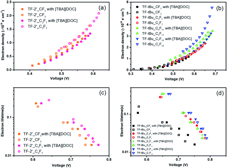
To further probe the device performances, the charge extraction (CE) and intensity-modulated photovoltage spectroscopy (IMVS) were measured and the corresponding data are shown in Fig. 3(a)–(d). The differences in the VOC between the cells can generally be explained by shifts in the TiO2 conduction band edge50,51 and differences in electron lifetimes in response to the electron recombination reaction.52–54Fig. 3(a) and (b) showed the extracted charge density at various recorded VOC's for DSC devices fabricated using studied sensitizers. It is worth noting that VOC decays are dependent on the accumulated charge in the TiO2 conduction band, and so to obtain a fair comparison of the recombination dynamics between different sensitizers, their charge density must be equal. It appears that similar electron densities were obtained for both TF-2′ sensitizers, independent to the CF3 and C3F7 substituents. On the other hand, addition of co-adsorbent yielded an increased VOC, which can be explained by a negative surface charge buildup that caused the band edges to shift upward, giving a higher photovoltage. As for the TF-tBu series of sensitizers, all cells fabricated with co-adsorbent showed relatively higher VOC compared with those without co-adsorbent. Moreover, cells fabricated with TF-tBu_C5F11 and TF-tBu_C7F15 in absence of co-adsorbent showed the lowest and the second lowest VOC, while TF-tBu_CF3 and TF-tBu_C3F7 regained their high VOC in absence of co-adsorbent, showing the advantage of shortened fluoroalkyl groups, i.e. CF3 and C3F7.
Fig. 3(c) and (d) showed the plot of electron lifetime versus VOC of the studied devices, as obtained from the IMVS experiments. In general, all TF-2′ and TF-tBu sensitizers with the longer perfluoroalkyl substituents showed longer lifetime at any given VOC. Particularly, in the TF-tBu series of sensitizers, the TF-tBu_CF3 showed the shortest lifetime and fastest recombination, while those with C3F7 and higher fluoroalkyl group (i.e. C5F11 and C7F15) exhibited comparable long electron lifetime, an observation that is attributed to the gradually reduced influence on variation of chain length. Overall, the combined CE and IMVS results indicated that devices constructed with those bearing longer perfluoroalkyl chain show more stabilized conduction band edge in absence of co-adsorbent, and longer lifetimes due to the suppressed back-electron transfer (i.e. charge recombination).
To clarify the governing factors on the photovoltaic performances of DSC devices, electrochemical impedance spectroscopy was also utilized to analyze the resistance to charge recombination in these devices. Nyquist plots were measured in the dark with varied forward bias. The data obtained during an electrochemical impedance measurement is usually conducted by fitting the experimental results with an equivalent circuit.55,56 Fig. 4 showed the trend of charge transfer resistance (RCT) at the interface of TiO2/dye/electrolyte,57 among which Fig. 4(a) demonstrated the electrochemical impedance illustration of both TF-2′_CF3 and TF-2′_C3F7, and in presence and absence of [TBA][DOC], for which all studies showed highly similar RCT at the same applied bias, as well as the slightly larger RCT for the sensitizer TF-2′_C3F7. Similarly, as depicted in Fig. 4(b), the TF-tBu series of sensitizers showed similar RCT, which was independent to the co-adsorbent [TBA][DOC]. In addition, the RCT is increased with the length of perfluoroalkyl substituents. The highest resistance is obtained for the TF-tBu_C7F15 devices, confirming the trend obtained for the TF-2′ derivatives; i.e. longer chain length would prevent the electron recombination at the TiO2/dye/electrolyte interface.
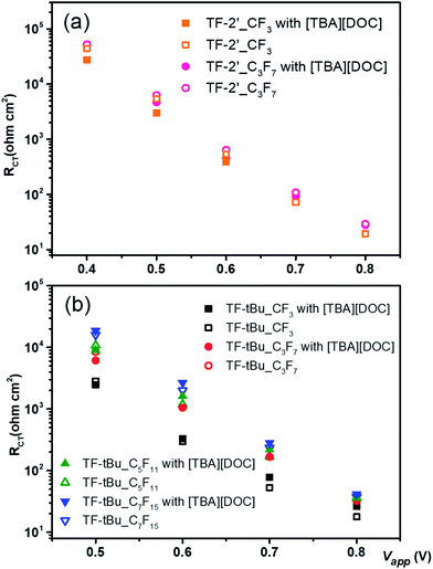 | ||
| Fig. 4 Electrochemical impedance spectra of DSC devices tested in dark with an external bias as each corresponding VOC under one-sun illumination. | ||
Sensitizer wettability
Modification of interfacial contact induced by changing the perfluoroalkyl substituents can be studied by contact angle measurements.58 Generally speaking, contact angles of >90° indicate relatively hydrophobic character, while values of <90° denote the hydrophilic surface under examination.59,60 Fig. 5 shows the illustration of contact angles (CA) upon application of 0.05 mL of water droplet at the sensitized TiO2 film. It appears that the parent sensitizers TF-2′ and TF-tBu_CF3 produce similar contact angles of 14.03° and 13.81°, showing the reduced hydrophobic character. Then, the sensitizers modified with C3F7 fragments became more hydrophobic by showing CA of 30.14° and 60.78° for TF-2′_C3F7 and TF-tBu_C3F7, respectively. Finally, the sensitizers TF-tBu_C5F11 and TF-tBu_C7F15 exhibited the much greater CA value of 76.82° and 122.20°. This result is consistent with the findings in IMVS, for which the longer perfluoroalkyl chain would prevent the electron recombination at the TiO2 interface.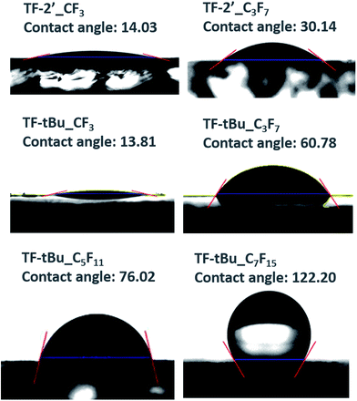 | ||
| Fig. 5 Contact angles of the sensitizers with different perfluoroalkyl side chain at the surface of dye-coated TiO2 films. | ||
Device stability
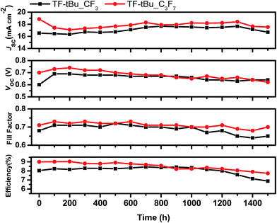
To test the long-term stability, two representative solar cells were fabricated using TF-tBu_CF3 and TF-tBu_C3F7, together with a low-volatility electrolyte composed of 1 M DMPII, 0.15 M I2, 0.2 M NaI, 0.1 M GuNCS, and 0.5 M NBB (N-butyl-1H-benzimidazole) in 3-methoxypropionitrile (MPN).61 Both cells were subjected to the accelerated light soaking test at 65 °C for 1500 h. Their performances are summarized in Fig. 6. As can be seen, both TF-tBu_CF3 and TF-tBu_C3F7-based cells showed consistently higher performances in JSC, VOC, and FF. Of particular interest are the final PCE (η) and the decay in efficiency (Δ), which is defined as (ηmax − η1500 h)/ηmax. They were calculated to be PCE = 8.33%, Δ = 8.36% for TF-tBu_C3F7, and PCE = 7.0%, Δ = 21.6% for TF-tBu_CF3. The excellent stability of TF-tBu_C3F7 over that of TF-tBu_CF3 indicates its potential advantage for fabrication of the solar modules with adequate stability.Larger sized devices
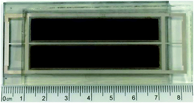
Large sized solar cell module using TF-tBu_C3F7 sensitizer was also fabricated in an attempt to verify their potential usage in actual application.62 As shown in Fig. 7, the fabricated DSC module consists of two parallel TiO2 strips, each coated with a 15 μm of the dye-absorbing layer (20 nm) plus a larger diameter light scattering layer (5 μm, 400 nm), giving a total active area of 0.98 × 5.7 × 2 cm2 (e.g. 11.2 cm2). The cell was fabricated using the previously mentioned protocol, except that a grid of silver wires was printed on both TiO2 anode and Pt-based counter electrode using commercial silver paste to improve the collection of photocurrent. The silver wires were next covered by glass paste to protect against the possible corrosion and unwanted contact with the electrolyte. After then, the cell was carefully assembled using Surlyn to ensure good insulation around the silver grids. The performances are listed in Table 3, showing a JSC of 18.51 mA cm−2, a VOC of 737 mV, a FF of 0.55 and PCE of 7.55% under the standard AM 1.5 G solar irradiation. As can be seen, the JSC and VOC are comparable to those of the smaller area DSC devices, while the large reduction in FF is due to the inefficient collection of photocurrent and the increased diffusion resistance.| Sensitizer | Coads.b | VOC [mV] | JSC [mA cm−2] | FF | PCE [%] |
|---|---|---|---|---|---|
| a The devices were fabricated using a 15 + 5 μm of TiO2 layer with an active area of 0.98 × 5.7 × 2 cm2 (e.g. 11.2 cm2).b Y and N stand for the cells fabricated with and without the addition of co-adsorbent during dyeing. | |||||
| TF-tBu_C3F7 | Y | 747(3) | 15.57(15) | 0.61(1) | 7.11(6) |
| N | 737(3) | 18.51(4) | 0.55(1) | 7.55(7) | |
Performance under indoor lighting
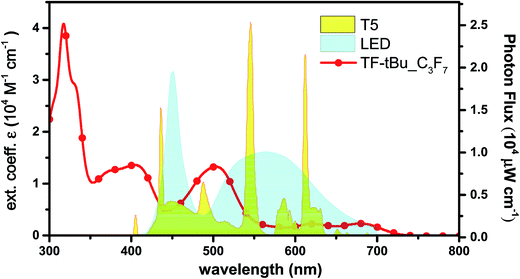
DSCs are known to exhibit better performance vs. thin film silicon solar cells under ambient lighting, which open up the possibility to use DSCs as the constant power sources with reduced electric output in an indoor environment.63 In this study, we employed TF-tBu_C3F7 which is structurally simple, no need to add the co-adsorbent in dye solution and good power conversion efficiency in this series. It serves a candidate for measurement of DSC performance under indoor lighting. In Fig. 8, we compared the absorption spectrum of TF-tBu_C3F7 in the solution, together with emission spectral profiles of commercially available, T5 fluorescent tube and LED lamp.Photovoltaic characters of the normal cell fabricated using TF-tBu_C3F7 and with dimension of 0.25 cm2 under various light intensities between 600 and 2400 lux are depicted in Table 4. Under illumination of standard T5 lamp, the device exhibits a JSC of 0.08 mA cm−2 (at 600 lux) to 0.32 mA cm−2 (at 2400 lux) and a VOC of 540 mV (600 lux) to 600 mV (2400 lux), whereas under normal LED illumination, the cell provides a JSC of 0.07 mA cm−2 (600 lux) to 0.27 mA cm−2 (2400 lux) and a VOC of 520 mV (600 lux) to 590 mV (2400 lux). The employed light intensities (600, 1200 and 2400 lux) were based on the standard indoor illumination between 200 and 2000 lux.63 The slightly better performance recorded at higher luminance is attributed to an increased light intensity that reduced the influence of the variation of dark current. Overall, the cell generates an electric power efficiency of 0.69 mW cm−2 (PCE = 20.4%) and 0.73 mW cm−2 (PCE = 16.1%) under the illumination of T5 lamp and LED, respectively. Then, we switched to the large sized module with area and measured their corresponding performances under the indoor lighting, for which the data are listed in Table 5. In general, the device gave slightly better performances under T5 vs. LED illumination, for which the best performances were JSC of 0.24 mA cm−2, VOC of 0.52 mV, FF of 0.72 and PCE of 12.7% at 2400 lux. Therefore, these optimal efficiencies under indoor confirms the better opportunity for DSC in harvesting ambient light energy vs. that for terrestrial power generation.63–65
| Source | Lux | Light intensity (mW cm−2) | VOC [mV] | JSC [mA cm−2] | FF | PCE [%] |
|---|---|---|---|---|---|---|
| a The cell consists of a dimension of 0.5 × 0.5 cm2. | ||||||
| T5 | 600 | 0.176 | 540(3) | 0.08(13) | 0.73(1) | 16.68(3) |
| 1200 | 0.344 | 570(7) | 0.16(14) | 0.73(1) | 19.14(6) | |
| 2400 | 0.693 | 600(5) | 0.32(16) | 0.74(1) | 20.37(2) | |
| LED | 600 | 0.184 | 520(5) | 0.07(13) | 0.67(1) | 13.84(4) |
| 1200 | 0.367 | 560(3) | 0.14(17) | 0.73(1) | 15.48(5) | |
| 2400 | 0.730 | 590(5) | 0.27(15) | 0.73(1) | 16.05(3) | |
| Source | Lux | Light intensity (mW cm−2) | VOC [mV] | JSC [mA cm−2] | FF | PCE [%] |
|---|---|---|---|---|---|---|
| a The devices were fabricated using a 15 + 5 μm of TiO2 layer with an active area of 0.98 × 5.7 × 2 cm2 (e.g. 11.2 cm2). | ||||||
| T5 | 600 | 0.176 | 460(5) | 0.06(30) | 0.68(1) | 10.05(8) |
| 1200 | 0.342 | 490(7) | 0.12(10) | 0.70(1) | 11.82(4) | |
| 2400 | 0.696 | 520(6) | 0.24(12) | 0.72(1) | 12.70(6) | |
| LED | 600 | 0.183 | 450(7) | 0.05(18) | 0.67(1) | 8.07(10) |
| 1200 | 0.363 | 480(5) | 0.10(12) | 0.70(1) | 9.37(3) | |
| 2400 | 0.725 | 510(5) | 0.20(15) | 0.74(1) | 10.51(9) | |
3. Conclusion
A total of six distinctive, 4,4′,4′′-tricarboxy-2,2′:6′,2′′-terpyridine based Ru(II) sensitizers, i.e. TF-2′_CnF2n+1 (n = 1 and 3) and TF-tBu_CnF2n+1 (n = 1, 3, 5 and 7) with either 5-dodecylthien-2-yl (TF-2′) or t-butyl substituent (TF-tBu) at the central pyridyl unit and four distinctive perfluoroalkyl fragments (e.g. CF3, C3F7, C5F11 and C7F15) at both terminal pyrazolyl sites of the 2,6-dipyrazolyl pyridine ancillary are synthesized and tested for DSC performances. Disregarding to the higher extinction coefficient of the 5-dodecylthien-2-yl substituted sensitizers versus the t-butyl substituted analogues, the latter showed the best overall PCE of 10.05% for TF-tBu_C3F7 vs. those of corresponding TF-2′_C3F7 (9.61%), which are attributed to the increased loading on the sensitized TiO2 surface. Particularly, the introduction of C3F7 substituent also eliminate the necessity of using co-adsorbent, which is beneficial for increasing the lifespan of DSC under the practical operating condition. Moreover, due to an ample supply of C3F7 substituted 2,6-dipyrazolyl pyridine ancillary, TF-tBu_C3F7 sensitizer was mass produced to allow the fabrication of DSC module, which showed an active-area of 11.2 cm2 and overall performances of JSC = 18.51 mA cm−2, VOC = 737 mV, FF = 0.55 and PCE = 7.55% under simulated one sun irradiation. Upon placed under indoor lighting (T5 lamp), it showed an improved PCE of 12.70% due to the better spectral matching between sensitizer and illumination source. Hence, the gained experiences should be of valuable to the future application of DSC devices.4. Experimental section
Device fabrication
The pre-cleaned FTO glasses (4 mm thickness, Nippon Sheet Glass Co., Japan) were immersed in a 40 mM aqueous TiCl4 solution at 75 °C for 30 min, followed by washing with water and ethanol. They were then deposited with 15 μm of 20 nm TiO2 particles, followed by a 5 μm scattering layer containing 400 nm TiO2 particles (PST-400, JGC Catalysts and Chemicals, Japan). The TiO2 electrodes were heated in air at 325 °C for 30 min, followed by heating at 375 °C for 5 min, 450 °C for 15 min, and 500 °C for 30 min. They were next treated with 40 mM aqueous solution of TiCl4 for 30 min at 75 °C, followed by heating at 500 °C for 30 min. Subsequently, these TiO2 films were immersed in a dye solution for 18 h at 25 °C. The dye solution contained 0.3 mM of each sensitizer in 1-propanol, along with 0.6 mM of tetra-butylammonium deoxycholate [TBA][DOC], and 0.3 mM of each sensitizer contained the 20% DMSO in ethanol.Procedures for device measurement
Photovoltaic measurements were tested under a class-AAA solar simulator (Model 11016A, Sun 3000, ABET Technologies) equipped with a 550 W xenon light source and water-cooling stage (25 °C). The current–voltage characteristic of each cell was obtained using a Keithley digital source meter (Model 2400). The spectra of incident photon-to-current conversion efficiency (IPCE) were calculated with the equation of 1240JSC(λ)/(λPin(λ)) where JSC is the short-circuit current density under each monochromatic illumination in unit of A cm−2, λ is the wavelength of incident monochromatic light in unit of nanometer, and Pin is the monochromatic light intensity in unit of W cm−2. 10 values of JSC (interval 50 ms) were collected sequentially after illuminating the device for 3 seconds and then averaged for calculation of IPCE. A 300 W Xe lamp (Model 6258, Newport Oriel) combined with an Oriel cornerstone 260 1/4 m monochromator (Model 74100) provided a device under test with a monochromatic beam (DC mode). The beam power intensity was calibrated with a power meter (Model 1936-C, Newport) equipped with a Newport 818-UV photodetector.Photophysical measurements of DSC devices
Charge extraction (CE) was measured with the PGSTAT302N electrochemical workstation (Autolab) at an open-circuit condition for the photovoltage of the device to attain a steady state. The red light-emitting diode (LED, 627 nm) was switched off while the device was simultaneously switched to a short-circuit condition to measure the excess charges generated in the film. Intensity-modulated photovoltage spectroscopy (IMVS) measurement was conducted using the same electrochemical workstation equipped with a frequency response analyzer (FRA) to drive a red light emitting diode. The analysis of the photovoltage response of the cells was conducted in the frequency range of 104 to 1 Hz and LED supplied the AC (modulation depth 10%) perturbation current superimposed on the DC current.Device performance measured under indoor illumination
This system is composed of a standardized T5 fluorescent lamp (FH14D-EX/T, China Electric Mfg Corporation, Taiwan) or a LED light source (FOP/A/40W/757/U/2×2, Everlight, Taiwan), of which both are mounted on the motor-controlled vertical tracks. The setup is equipped with a calibrated spectroradiometer (ISM-Lux, Isuzu Optics, Japan), and selective levels of illumination are achieved by changing the relatively height of T5 or LED lamp vs. the spectroradiometer (or DSC cells). The J–V curves were recorded with a computer-controlled digital source meter (Keithley 2400C, USA) at various indoor lighting conditions.64,65Conflicts of interest
There are no conflicts of interest.References
- S. Zhang, X. Yang, Y. Numata and L. Han, Energy Environ. Sci., 2013, 6, 1443–1464 CAS.
- T. M. Brown, F. De Rossi, F. Di Giacomo, G. Mincuzzi, V. Zardetto, A. Reale and A. Di Carlo, J. Mater. Chem. A, 2014, 2, 10788–10817 CAS.
- Y. Bai, I. Mora-Seró, F. De Angelis, J. Bisquert and P. Wang, Chem. Rev., 2014, 114, 10095–10130 CrossRef CAS PubMed.
- K. G. Reddy, T. G. Deepak, G. S. Anjusree, S. Thomas, S. Vadukumpully, K. R. V. Subramanian, S. V. Nair and A. S. Nair, Phys. Chem. Chem. Phys., 2014, 16, 6838–6858 RSC.
- M.-E. Ragoussi and T. Torres, Chem. Commun., 2015, 51, 3957–3972 RSC.
- B. Pashaei, H. Shahroosvand, M. Graetzel and M. K. Nazeeruddin, Chem. Rev., 2016, 116, 9485–9564 CrossRef CAS PubMed.
- M. Pazoki, U. B. Cappel, E. M. J. Johansson, A. Hagfeldt and G. Boschloo, Energy Environ. Sci., 2017, 10, 672–709 CAS.
- L. Zhang and J. M. Cole, ACS Appl. Mater. Interfaces, 2015, 7, 3427–3455 CAS.
- J. Wu, Z. Lan, J. Lin, M. Huang, Y. Huang, L. Fan and G. Luo, Chem. Rev., 2015, 115, 2136–2173 CrossRef CAS PubMed.
- S. Thomas, T. G. Deepak, G. S. Anjusree, T. A. Arun, S. V. Nair and A. S. Nair, J. Mater. Chem. A, 2014, 2, 4474–4490 CAS.
- G. C. Vougioukalakis, A. I. Philippopoulos, T. Stergiopoulos and P. Falaras, Coord. Chem. Rev., 2011, 255, 2602–2621 CrossRef CAS.
- P. G. Bomben, K. C. D. Robson, B. D. Koivisto and C. P. Berlinguette, Coord. Chem. Rev., 2012, 256, 1438–1450 CrossRef CAS.
- Y. Chi, B. Tong and P.-T. Chou, Coord. Chem. Rev., 2014, 281, 1–25 CrossRef CAS.
- Y. Chi, K.-L. Wu and T.-C. Wei, Chem.–Asian J., 2015, 10, 1098–1115 CrossRef CAS PubMed.
- L.-L. Li and E. W.-G. Diau, Chem. Soc. Rev., 2013, 42, 291–304 RSC.
- T. Higashino and H. Imahori, Dalton Trans., 2015, 44, 448–463 RSC.
- S. Mathew, A. Yella, P. Gao, R. Humphry-Baker, F. E. CurchodBasile, N. Ashari-Astani, I. Tavernelli, U. Rothlisberger, M. K. Nazeeruddin and M. Grätzel, Nat. Chem., 2014, 6, 242–247 CrossRef CAS PubMed.
- Z. Yao, M. Zhang, R. Li, L. Yang, Y. Qiao and P. Wang, Angew. Chem., Int. Ed., 2015, 54, 5994–5998 CrossRef CAS PubMed.
- S. Ahmad, E. Guillen, L. Kavan, M. Gratzel and M. K. Nazeeruddin, Energy Environ. Sci., 2013, 6, 3439–3466 CAS.
- Y. Wu and W. Zhu, Chem. Soc. Rev., 2013, 42, 2039–2058 RSC.
- S. Chen, L. Yang, J. Zhang, Y. Yuan, X. Dong and P. Wang, ACS Photonics, 2017, 4, 165–173 CrossRef CAS.
- Y. Ren, J. Liu, A. Zheng, X. Dong and P. Wang, Adv. Sci., 2017, 4, 1700099 CrossRef.
- J.-F. Yin, M. Velayudham, D. Bhattacharya, H.-C. Lin and K.-L. Lu, Coord. Chem. Rev., 2012, 256, 3008–3035 CrossRef CAS.
- G. Koyyada, V. Botla, S. Thogiti, G. Wu, J. Li, X. Fang, F. Kong, S. Dai, N. Surukonti, B. Kotamarthi and C. Malapaka, Dalton Trans., 2014, 43, 14992–15003 RSC.
- W.-C. Chen, F.-T. Kong, Z.-Q. Li, J.-H. Pan, X.-P. Liu, F.-L. Guo, L. Zhou, Y. Huang, T. Yu and S.-Y. Dai, ACS Appl. Mater. Interfaces, 2016, 8, 19410–19417 CAS.
- L. Han, A. Islam, H. Chen, C. Malapaka, B. Chiranjeevi, S. Zhang, X. Yang and M. Yanagida, Energy Environ. Sci., 2012, 5, 6057–6060 CAS.
- H. Ozawa, Y. Okuyama and H. Arakawa, ChemPhysChem, 2014, 15, 1201–1206 CrossRef CAS PubMed.
- S.-W. Wang, C.-C. Chou, F.-C. Hu, K.-L. Wu, Y. Chi, J. N. Clifford, E. J. Palomares, S.-H. Liu, P.-T. Chou, T. C. Wei and T. Y. Hsiao, J. Mater. Chem. A, 2014, 2, 17618–17627 CAS.
- Y. Numata, S. P. Singh, A. Islam, M. Iwamura, A. Imai, K. Nozaki and L. Han, Adv. Funct. Mater., 2013, 23, 1817–1823 CrossRef CAS.
- C.-W. Hsu, S.-T. Ho, K.-L. Wu, Y. Chi, S.-H. Liu and P.-T. Chou, Energy Environ. Sci., 2012, 5, 7549–7554 CAS.
- D. G. Brown, P. A. Schauer, J. Borau-Garcia, B. R. Fancy and C. P. Berlinguette, J. Am. Chem. Soc., 2013, 135, 1692–1695 CrossRef CAS PubMed.
- B. Schulze, D. G. Brown, K. C. D. Robson, C. Friebe, M. Jäger, E. Birckner, C. P. Berlinguette and U. S. Schubert, Chem.–Eur. J., 2013, 19, 14171–14180 CrossRef CAS PubMed.
- G. Wu, R. Kaneko, K. Sugawa, A. Islam, I. Bedja, R. K. Gupta, L. Han and J. Otsuki, Dyes Pigm., 2017, 140, 354–362 CrossRef CAS.
- Y. Chi, T.-K. Chang, P. Ganesan and P. Rajakannu, Coord. Chem. Rev., 2017, 346, 91–100 CrossRef CAS.
- M. Hussain, A. Islam, I. Bedja, R. K. Gupta, L. Han and A. El-Shafei, Phys. Chem. Chem. Phys., 2014, 16, 14874–14881 RSC.
- G. Li, A. Yella, D. G. Brown, S. I. Gorelsky, M. K. Nazeeruddin, M. Grätzel, C. P. Berlinguette and M. Shatruk, Inorg. Chem., 2014, 53, 5417–5419 CrossRef CAS PubMed.
- M. Urbani, M. Medel, S. A. Kumar, M. Ince, A. N. Bhaskarwar, D. González-Rodríguez, M. Grätzel, M. K. Nazeeruddin and T. Torres, Chem.–Eur. J., 2015, 21, 16252–16265 CrossRef CAS PubMed.
- L. E. Polander, A. Yella, B. F. E. Curchod, A. N. Ashari, J. Teuscher, R. Scopelliti, P. Gao, S. Mathew, J.-E. Moser, I. Tavernelli, U. Rothlisberger, M. Gratzel, M. K. Nazeeruddin and J. Frey, Angew. Chem., Int. Ed., 2013, 52, 8731–8735 CrossRef CAS PubMed.
- G. Li, K. Hu, K. C. D. Robson, S. I. Gorelsky, G. J. Meyer, C. P. Berlinguette and M. Shatruk, Chem.–Eur. J., 2015, 21, 2173–2181 CrossRef CAS PubMed.
- J.-Y. Li, C. Lee, C.-Y. Chen, W.-L. Lee, R. Ma and C.-G. Wu, Inorg. Chem., 2015, 54, 10483–10489 CrossRef CAS PubMed.
- A. Colombo, C. Dragonetti, M. Magni, D. Meroni, R. Ugo, G. Marotta, M. Grazia Lobello, P. Salvatori and F. De Angelis, Dalton Trans., 2015, 44, 11788–11796 RSC.
- S. Inoue, H. Minemawari, J. Y. Tsutsumi, M. Chikamatsu, T. Yamada, S. Horiuchi, M. Tanaka, R. Kumai, M. Yoneya and T. Hasegawa, Chem. Mater., 2015, 27, 3809–3812 CrossRef CAS.
- S. Maniam, A. B. Holmes, G. A. Leeke, A. Bilic and G. E. Collis, Org. Lett., 2015, 17, 4022–4025 CrossRef CAS PubMed.
- K.-L. Wu, W.-P. Ku, J. N. Clifford, E. Palomares, S.-T. Ho, Y. Chi, S.-H. Liu, P.-T. Chou, M. K. Nazeeruddin and M. Grätzel, Energy Environ. Sci., 2013, 6, 859–870 CAS.
- C.-C. Chou, F.-C. Hu, H.-H. Yeh, H.-P. Wu, Y. Chi, J. N. Clifford, E. Palomares, S.-H. Liu, P.-T. Chou and G.-H. Lee, Angew. Chem., Int. Ed., 2014, 53, 178–183 CrossRef CAS PubMed.
- H.-Y. Ku, B. Tong, Y. Chi, H.-C. Kao, C.-C. Yeh, C.-H. Chang and G.-H. Lee, Dalton Trans., 2015, 44, 8552–8563 RSC.
- S.-H. Yang, K.-L. Wu, Y. Chi, Y.-M. Cheng and P.-T. Chou, Angew. Chem., Int. Ed., 2011, 50, 8270–8274 CrossRef CAS PubMed.
- K.-L. Wu, S.-T. Ho, C.-C. Chou, Y.-C. Chang, H.-A. Pan, Y. Chi and P.-T. Chou, Angew. Chem., Int. Ed., 2012, 51, 5642–5646 CrossRef CAS PubMed.
- V. S. Manthou, E. K. Pefkianakis, P. Falaras and G. C. Vougioukalakis, ChemSusChem, 2015, 8, 588–599 CrossRef CAS PubMed.
- Z. Zhang, S. M. Zakeeruddin, B. C. O'Regan, R. Humphry-Baker and M. Grätzel, J. Phys. Chem. B, 2005, 109, 21818–21824 CrossRef CAS PubMed.
- D. P. Hagberg, J.-H. Yum, H. Lee, F. De Angelis, T. Marinado, K. M. Karlsson, R. Humphry-Baker, L. Sun, A. Hagfeldt, M. Grätzel and M. K. Nazeeruddin, J. Am. Chem. Soc., 2008, 130, 6259–6266 CrossRef CAS PubMed.
- B. C. O'Regan and J. R. Durrant, Acc. Chem. Res., 2009, 42, 1799–1808 CrossRef PubMed.
- B. C. O'Regan, K. Walley, M. Juozapavicius, A. Anderson, F. Matar, T. Ghaddar, S. M. Zakeeruddin, C. Klein and J. R. Durrant, J. Am. Chem. Soc., 2009, 131, 3541–3548 CrossRef PubMed.
- J. N. Clifford, E. Martinez-Ferrero and E. Palomares, J. Mater. Chem., 2012, 22, 12415–12422 RSC.
- Q. Wang, S. Ito, M. Grätzel, F. Fabregat-Santiago, I. Mora-Seró, J. Bisquert and T. Bessho, J. Phys. Chem. B, 2006, 110, 25210–25221 CrossRef CAS PubMed.
- N. Karjule, M. K. Munavvar Fairoos and N. Jayaraj, J. Mater. Chem. A, 2016, 4, 18910–18921 CAS.
- Q. Wang, J.-E. Moser and M. Grätzel, J. Phys. Chem. B, 2005, 109, 14945–14953 CrossRef CAS PubMed.
- N. Giovambattista, P. G. Debenedetti and P. J. Rossky, J. Phys. Chem. B, 2007, 111, 9581–9587 CrossRef CAS PubMed.
- V. Leandri, H. Ellis, E. Gabrielsson, L. Sun, G. Boschloo and A. Hagfeldt, Phys. Chem. Chem. Phys., 2014, 16, 19964–19971 RSC.
- H. Zhang, L. Qiu, D. Xu, W. Zhang and F. Yan, J. Mater. Chem. A, 2014, 2, 2221–2226 CAS.
- D. Kuang, C. Klein, S. Ito, J.-E. Moser, R. Humphry-Baker, N. Evans, F. Duriaux, C. Grätzel, S. M. Zakeeruddin and M. Grätzel, Adv. Mater., 2007, 19, 1133–1137 CrossRef CAS.
- T.-K. Chang, H. Li, K.-T. Chen, Y.-C. Tsai, Y. Chi, T.-Y. Hsiao and J.-J. Kai, J. Mater. Chem. A, 2015, 3, 18422–18431 CAS.
- M. Freitag, J. Teuscher, Y. Saygili, X. Zhang, F. Giordano, P. Liska, J. Hua, S. M. Zakeeruddin, J.-E. Moser, M. Grätzel and A. Hagfeldt, Nat. Photonics, 2017, 11, 372–378 CrossRef CAS.
- Y.-C. Liu, H.-H. Chou, F.-Y. Ho, H.-J. Wei, T.-C. Wei and C.-Y. Yeh, J. Mater. Chem. A, 2016, 4, 11878–11887 CAS.
- C.-L. Wang, P.-T. Lin, Y.-F. Wang, C.-W. Chang, B.-Z. Lin, H.-H. Kuo, C.-W. Hsu, S.-H. Tu and C.-Y. Lin, J. Phys. Chem. C, 2015, 119, 24282–24289 CAS.
Footnote |
| † Electronic supplementary information (ESI) available. See DOI: 10.1039/c7ra07379h |
| This journal is © The Royal Society of Chemistry 2017 |

