 Open Access Article
Creative Commons Attribution 3.0 Unported Licence
Optically observed multiple inter-chain interactions in polyblend semiconducting polymer nanoparticles
Z. Hashim *a,
S. Alomaria,
W. Alghamdia,
R. Altuwirqia and
M. Green
 b
b
aDepartment of Physics, Faculty of Sciences, King Abdulaziz University, Jeddah, Saudi Arabia. E-mail: zmhashim@kau.edu.sa
bDepartment of Physics, King's College London, Strand, London, WC2R 2LS, UK. E-mail: mark.a.green@kcl.ac.uk
First published on 16th October 2017
Abstract
F8BT:MEH-PPV:CN-PPV semiconducting polymer blend nanoparticles (SPNs) were synthesized with different ratios by a miniemulsion route from three different conjugated polymers; two red/orange emitting polymers; poly[2-methoxy-5-(2-ethylhexyloxy)-1,4-phenylenevinylene] (MEH-PPV) and poly(2,5-di(hexyloxy)cyanoterephthalylidene) (CN-PPV), and one green emitting polymer poly(9,9-dioctylfluorene-alt-benzothiadiazole) (F8BT). The resulting SPNs were spherical in shape as determined by transmission electron microscopy, and exhibited tuneable photoluminescence. These optical properties were attributed to the inter-chain interactions between F8BT and the MEH-PPV, and between MEH-PPV and CN-PPV within the same nanoparticle, with no direct interactions happening between the chains of F8BT and the chains of CN-PPV. Therefore, the presence of MEH-PPV within the polyblend SPNs facilitated an indirect F8BT:CN-PPV interaction that was not possible before.
Introduction
Semiconducting polymer nanoparticles (SPNs) are fluorescent materials which are proposed as alternatives to inorganic quantum dots.1 SPNs have better fluorescence stability with longer shelf-lives, are composed of benign or less-toxic materials, and can be synthesized by an environmentally friendly and relatively easy method (miniemulsion) that does not require any heating, and can be performed in ambient conditions. Many applications require fluorescence within a specific range of wavelengths, selected for the relevant end-use.2 Nanoparticles engineered for these applications must, therefore, have stable emission that does not change or quench in their intended environment over the period of storage and use. Unlike quantum dots,3,4 SPNs have emission colors that do not shift with the change in their size.5–7 However, if a different emission color is required, the SPNs' parent polymer must be changed or a dopant molecule8 or further polymer9 must be introduced within the same nanoparticle during the synthesis process to facilitate inter-chain interactions that result in the required fluorescence change. A key method for tuning the optical properties of SPNs is by preparing polymer blends prior to nanoparticle formation, resulting in what can be referred to as polyblend SPNs.10Several studies reported the synthesis of polyblend SPNs from a blend of two conjugated polymers;11,12 Huebner et al.12 reported the synthesis of PFO:POPPV SPNs from a blend of a blue emitting (PFO) and a green emitting (POPPV) polymer. The blending resulted in a material with controllable photoemission caused by the tunable energy transfer within the nanoparticles. This energy transfer was also reported by McNeill et al.11 when blending F8BT with MEH-PPV. The blend caused the total quenching of F8BT emission and an increase in the optical quantum yield of the new MEH-PPV-emitting polyblend SPNs. Color control of polyblend SPNs could pave the way towards the production of white emitting nanoparticles from a blend of polymers with different emission colors,13 while fluorescence emission enhancement of pre-existing polymer nanoparticles by doping them with trace amounts of other polymers could increase their emission efficiency.14 Some polyblend SPNs were also found to have multiple electron densities within one nanoparticle. This phase separation phenomena can be utilized to form core/shell structures similar to those of QDs.13
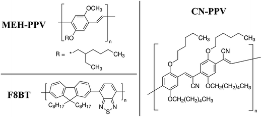
In this study, we report the synthesis of new polyblend SPNs synthesized from the blend of three conjugated polymers; F8BT, MEH-PPV, and CN-PPV (polymer structures shown in Fig. 1). The new F8BT:MEH-PPV:CN-PPV SPNs have controllable optical absorption and tunable emission which can be altered by the modification of the polymers' ratios in the SPNs.
Results and discussion
Fig. 2 shows TEM images of the prepared F8BT:MEH-PPV:CN-PPV SPNs. The synthesized nanoparticles were mostly spherical and their sizes ranged between tens of nanometers and a few hundred nanometers in diameter (the diameter size distribution of a typical sample is shown in Fig. 3, mean diameter = 90.6 nm). This broad particle range is expected from a miniemulsion synthesis process, and can be minimized with further emulsion control.5 The SDS coating was also visible especially around the larger particles (Fig. 2C, E, and F). Fig. 2C and D also show uneven electron density within the same particle, previously assigned as phase separation in blended polymer nanoparticles.15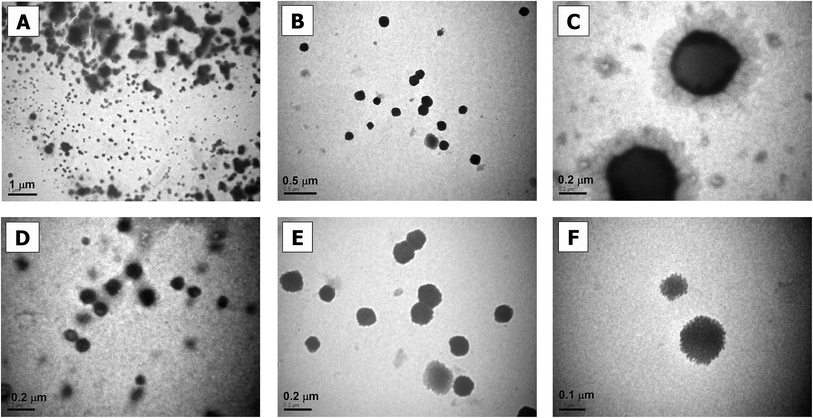 | ||
| Fig. 2 TEM images of F8BT:MEH-PPV:CN-PPV SPNs. Bar-scales are 1 μm in (A), 0.5 μm in (B), 0.2 μm in (C–E), and 100 nm in (F). | ||
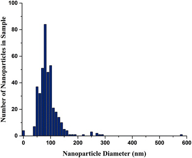 | ||
| Fig. 3 F8BT:MEH-PPV:CN-PPV SPNs diameter size distribution, measured from TEM images, 400 counts, using ImageJ. | ||
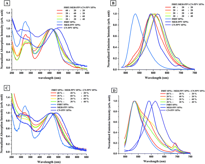
The absorption spectra of F8BT:MEH-PPV:CN-PPV SPNs and of SPNs prepared from the individual polymers are shown in Fig. 4A. The peaks of the absorption spectra of F8BT:MEH-PPV:CN-PPV SPNs in the visible region, i.e. between 390–700 nm, overlaid those of both CN-PPV SPNs and F8BT SPNs, but their widths varied between both nanoparticles. The second absorption peaks of F8BT:MEH-PPV:CN-PPV SPNs, which appeared in the ultraviolet region, i.e. between 375–390 nm, followed the shape of F8BT SPNs but had lower, variable, intensities.
The emission spectra of F8BT:MEH-PPV:CN-PPV SPNs and of SPNs prepared from the individual polymers are shown in Fig. 4B. The nanoparticles prepared from the blend of the three polymers had only one emission peak between 500–750 nm which was similar to that of CN-PPV SPNs and MEH-PPV SPNs, with its peak value shifting between the peak values of the two red emitting polymer SPNs, and its emission width widening to cover both spectra. Moreover, although the presence of F8BT was suggested by the absorption spectra, there was no sign of the existence of the fluorescence of F8BT in the nanoparticles prepared with low ratios of F8BT (which should appear as a second peak or a shoulder around λem = 536 nm), and there was only a small shoulder at that wavelength in the SPNs prepared with the highest F8BT ratio (i.e. 60![[thin space (1/6-em)]](https://www.rsc.org/images/entities/char_2009.gif) :
:![[thin space (1/6-em)]](https://www.rsc.org/images/entities/char_2009.gif) 20
20![[thin space (1/6-em)]](https://www.rsc.org/images/entities/char_2009.gif) :
:![[thin space (1/6-em)]](https://www.rsc.org/images/entities/char_2009.gif) 20 SPNs). F8BT is known to have a substantially higher fluorescence quantum yield than MEH-PPV,16 and the existence of only a small shoulder around its emission peak of 60
20 SPNs). F8BT is known to have a substantially higher fluorescence quantum yield than MEH-PPV,16 and the existence of only a small shoulder around its emission peak of 60![[thin space (1/6-em)]](https://www.rsc.org/images/entities/char_2009.gif) :
:![[thin space (1/6-em)]](https://www.rsc.org/images/entities/char_2009.gif) 20
20![[thin space (1/6-em)]](https://www.rsc.org/images/entities/char_2009.gif) :
:![[thin space (1/6-em)]](https://www.rsc.org/images/entities/char_2009.gif) 20 SPNs and its total disappearance, in the samples with lower F8BT ratios, suggest that there was an interaction between F8BT and at least one of the other polymers.
20 SPNs and its total disappearance, in the samples with lower F8BT ratios, suggest that there was an interaction between F8BT and at least one of the other polymers.
To investigate if this behavior was due to the compact configuration of the three polymers in one nanoparticle or merely due to the existence of the polymers in separate nanoparticles in the same solution, mixtures of pre-synthesised MEH-PPV SPNs, F8BT SPNs, and CN-PPV SPNs with percentages similar to the ratios used in the F8BT:MEH-PPV:CN-PPV SPNs' synthesis were prepared and optically analyzed. Fig. 4C shows the absorption spectra of the mixture of the individual SPNs. The absorption spectra in the visible region were similar to those of the polyblend SPNs, however, they did not exhibit features associated with F8BT SPNs in the mixture except when their concentration in the mixture was dominating (i.e. 60%![[thin space (1/6-em)]](https://www.rsc.org/images/entities/char_2009.gif) :
:![[thin space (1/6-em)]](https://www.rsc.org/images/entities/char_2009.gif) 20%
20%![[thin space (1/6-em)]](https://www.rsc.org/images/entities/char_2009.gif) :
:![[thin space (1/6-em)]](https://www.rsc.org/images/entities/char_2009.gif) 20% mixture).
20% mixture).
Comparison of the emission spectra from the mixture of the individual SPNs (Fig. 4D) and the F8BT:MEH-PPV:CN-PPV SPNs (Fig. 4B) showed a marked difference, with F8BT's peak dominating in all nanoparticles' mixtures prepared. The emission peak broadened with the increase in the percentages of MEH-PPV SPNs and CN-PPV SPNs, and had the widest broadening with the highest percentage of CN-PPV SPNs. Whilst referring to our previous work on these systems,5,16 we suggest that there were no interactions between the polymer nanoparticles when mixed, with each nanoparticulate species exhibiting their individual absorption and emissive characteristics.
The differences between the spectra of F8BT:MEH-PPV:CN-PPV SPNs and the mixture of the individual SPNs in Fig. 4 support our hypothesis of optically-observable electronic interactions between the polymers when brought together in one nanoparticulate configuration.
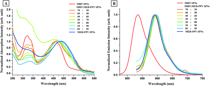
To understand this change in the optical properties of F8BT:MEH-PPV:CN-PPV SPNs and to identify which polymers interacted in this new configuration, one must first understand the inter-chain interactions between two polymers of the three when brought together in one-nanoparticle configuration. Fig. 5 shows the absorption and emission spectra of SPNs prepared from blends of F8BT and MEH-PPV with different ratios. The spectra of SPNs prepared from the individual polymers were also included for comparison. The absorption features of F8BT:MEH-PPV SPNs in the visible region (Fig. 5A), shifted slightly between the two constituent peaks of the SPNs made from their respective polymers, however the widths widened to cover both peaks. The shift was consistent and dependant on the ratios used, with the peaks shifting closer to the feature exhibited by the dominant polymer. There was also a change in the absorption spectra of F8BT:MEH-PPV SPNs in the UV region with the feature shape mostly resembling that of F8BT and decreasing in intensity with the decrease in its ratio. The emission spectra of F8BT:MEH-PPV SPNs with different polymer ratios (Fig. 5B) exhibited emission with spectra position, shape, and width consistent with pure MEH-PPV SPNs, with negligible variations. This was found to be the case even for SPNs which contained higher F8BT ratios despite the fact that F8BT SPNs were reported previously to have significantly higher quantum yields than MEH-PPV SPNs.16 This optical behavior was explained previously9,11 as an energy transfer from F8BT to MEH-PPV which can also be used to explain the disappearance of F8BT's emission peak, or the appearance of only a small F8BT related shoulder in F8BT:MEH-PPV:CN-PPV SPNs.
MEH-PPV was also blended with CN-PPV in the synthesis to produce MEH-PPV:CN-PPV SPNs. The absorption and emission spectra of the SPNs prepared from the polymers individually and from polyblends of the two polymers with different ratios are shown in Fig. 6. The absorption features of MEH-PPV:CN-PPV SPNs in the visible region were similar to those of the SPNs prepared from their constituent polymers, with the maxima of the visible-region's peak of seven of the nine SPNs prepared with different ratios coinciding with the maximum of CN-PPV SPNs, although this peak (ca. 460 nm) was ∼32 nm blue-shifted from the peak of MEH-PPV SPNs (488 nm). The absorption maxima of the other two SPNs (70![[thin space (1/6-em)]](https://www.rsc.org/images/entities/char_2009.gif) :
:![[thin space (1/6-em)]](https://www.rsc.org/images/entities/char_2009.gif) 30 and 30
30 and 30![[thin space (1/6-em)]](https://www.rsc.org/images/entities/char_2009.gif) :
:![[thin space (1/6-em)]](https://www.rsc.org/images/entities/char_2009.gif) 70 MEH-PPV
70 MEH-PPV![[thin space (1/6-em)]](https://www.rsc.org/images/entities/char_2009.gif) :
:![[thin space (1/6-em)]](https://www.rsc.org/images/entities/char_2009.gif) CN-PPV SPNs) were slightly shifted to the right (λabs,max = 471 nm for 70
CN-PPV SPNs) were slightly shifted to the right (λabs,max = 471 nm for 70![[thin space (1/6-em)]](https://www.rsc.org/images/entities/char_2009.gif) :
:![[thin space (1/6-em)]](https://www.rsc.org/images/entities/char_2009.gif) 30) or the left (λabs,max = 440 nm for 30
30) or the left (λabs,max = 440 nm for 30![[thin space (1/6-em)]](https://www.rsc.org/images/entities/char_2009.gif) :
:![[thin space (1/6-em)]](https://www.rsc.org/images/entities/char_2009.gif) 70) of the maximum of CN-PPV SPNs (λabs,max = 460 nm for CN-PPV SPNs). Despite this overlapping of the peaks' absorption maxima in the visible region, their peak widths did not always match that of CN-PPV SPNs but decreased with the decrease in CN-PPV's ratio to match that of MEH-PPV SPNs. This consistent decrease in absorption width was also followed by a consistent decrease in the absorption intensity of the SPNs in the UV region (320 nm). The emission spectra of MEH-PPV:CN-PPV SPNs shifted to the blue region (575 nm) with the decrease in the ratio of CN-PPV. The blue-shift was observed a few nanometers before the peak of CN-PPV SPNs (λem,max = 617 nm for 10
70) of the maximum of CN-PPV SPNs (λabs,max = 460 nm for CN-PPV SPNs). Despite this overlapping of the peaks' absorption maxima in the visible region, their peak widths did not always match that of CN-PPV SPNs but decreased with the decrease in CN-PPV's ratio to match that of MEH-PPV SPNs. This consistent decrease in absorption width was also followed by a consistent decrease in the absorption intensity of the SPNs in the UV region (320 nm). The emission spectra of MEH-PPV:CN-PPV SPNs shifted to the blue region (575 nm) with the decrease in the ratio of CN-PPV. The blue-shift was observed a few nanometers before the peak of CN-PPV SPNs (λem,max = 617 nm for 10![[thin space (1/6-em)]](https://www.rsc.org/images/entities/char_2009.gif) :
:![[thin space (1/6-em)]](https://www.rsc.org/images/entities/char_2009.gif) 90 MEH-PPV
90 MEH-PPV![[thin space (1/6-em)]](https://www.rsc.org/images/entities/char_2009.gif) :
:![[thin space (1/6-em)]](https://www.rsc.org/images/entities/char_2009.gif) CN-PPV SPNs, λem,max = 615 nm for CN-PPV SPNs), and bypassed the peak of MEH-PPV SPNs by 17 nm (λem,max = 575 nm for 90
CN-PPV SPNs, λem,max = 615 nm for CN-PPV SPNs), and bypassed the peak of MEH-PPV SPNs by 17 nm (λem,max = 575 nm for 90![[thin space (1/6-em)]](https://www.rsc.org/images/entities/char_2009.gif) :
:![[thin space (1/6-em)]](https://www.rsc.org/images/entities/char_2009.gif) 10 MEH-PPV
10 MEH-PPV![[thin space (1/6-em)]](https://www.rsc.org/images/entities/char_2009.gif) :
:![[thin space (1/6-em)]](https://www.rsc.org/images/entities/char_2009.gif) CN-PPV SPNs, λem,max = 592 nm for MEH-PPV SPNs). This 42 nm blue-shift revealed a different interaction when compared to F8BT and MEH-PPV in the F8BT:MEH-PPV SPNs. A similar blue shift with the increase in MEH-PPV's ratio to CN-PPV was also visible in the emission spectra of F8BT:MEH-PPV:CN-PPV SPNs (Fig. 4B). This suggest that the shift in F8BT:MEH-PPV:CN-PPV SPNs' emission peak with the change in the polymers' ratios was caused by an inter-chain interaction between the MEH-PPV and CN-PPV polymers in the nanoparticles.
CN-PPV SPNs, λem,max = 592 nm for MEH-PPV SPNs). This 42 nm blue-shift revealed a different interaction when compared to F8BT and MEH-PPV in the F8BT:MEH-PPV SPNs. A similar blue shift with the increase in MEH-PPV's ratio to CN-PPV was also visible in the emission spectra of F8BT:MEH-PPV:CN-PPV SPNs (Fig. 4B). This suggest that the shift in F8BT:MEH-PPV:CN-PPV SPNs' emission peak with the change in the polymers' ratios was caused by an inter-chain interaction between the MEH-PPV and CN-PPV polymers in the nanoparticles.
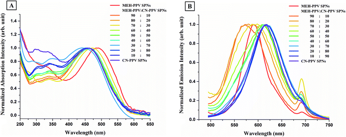 | ||
| Fig. 6 The (A) absorption and (B) emission spectra of MEH-PPV:CN-PPV SPNs, excitation wavelength = 460 nm. The spectra of the individual polymer SPNs are also drawn for comparison. | ||
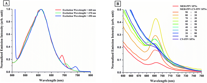
Fig. 6B also shows second small peaks in the red region of the spectra of MEH-PPV:CN-PPV SPNs, around λ = 691 nm. These second peaks were also visible in the emission spectra of both MEH-PPV SPNs and CN-PPV SPNs and were found to be excitation wavelength dependant, as shown in Fig. 7A. Changing the concentration of the same SPNs and re-measuring their emission spectrum (under the same excitation wavelength) did not cause a change in the intensity or position of that second peak. However, constantly increasing the ratio of one of the polymers to the other in MEH-PPV:CN-PPV SPNs caused a consistent change in its intensity, as shown in Fig. 7B.
CN-PPV was then blended with F8BT in different ratios, to produce F8BT:CN-PPV SPNs. Both polymers absorb in a similar visible region and their peak maxima lie at the same wavelength. The only difference between the absorption peaks of both polymers in the visible region is that the peak is broader for CN-PPV. Both polymers also absorb in the UV region however, F8BT has a more defined peak with a higher intensity than CN-PPV in that region. Fig. 8A shows the absorption spectra of the different F8BT:CN-PPV SPNs alongside the spectra of F8BT SPNs and CN-PPV SPNs. Decreasing the ratio of F8BT in the synthesis (from 90% to 10%) resulted in the broadening of the SPNs' peaks in the visible region and the decrease in their UV absorption (which followed the shape of F8BT for ratios 90![[thin space (1/6-em)]](https://www.rsc.org/images/entities/char_2009.gif) :
:![[thin space (1/6-em)]](https://www.rsc.org/images/entities/char_2009.gif) 10 to 30
10 to 30![[thin space (1/6-em)]](https://www.rsc.org/images/entities/char_2009.gif) :
:![[thin space (1/6-em)]](https://www.rsc.org/images/entities/char_2009.gif) 70 and the shape of CN-PPV for ratios 20
70 and the shape of CN-PPV for ratios 20![[thin space (1/6-em)]](https://www.rsc.org/images/entities/char_2009.gif) :
:![[thin space (1/6-em)]](https://www.rsc.org/images/entities/char_2009.gif) 80 and 10
80 and 10![[thin space (1/6-em)]](https://www.rsc.org/images/entities/char_2009.gif) :
:![[thin space (1/6-em)]](https://www.rsc.org/images/entities/char_2009.gif) 90). This suggests that SPNs with low UV absorption can be synthesized from a blend of polymers which have high UV absorption. The variation in the bandwidth of the absorption peaks in the visible region and the decrease in the UV absorption of F8BT:CN-PPV SPNs with the decrease in F8BT's ratio in the SPNs was also observed in the absorption spectra of F8BT:MEH-PPV:CN-PPV SPNs (Fig. 4A).
90). This suggests that SPNs with low UV absorption can be synthesized from a blend of polymers which have high UV absorption. The variation in the bandwidth of the absorption peaks in the visible region and the decrease in the UV absorption of F8BT:CN-PPV SPNs with the decrease in F8BT's ratio in the SPNs was also observed in the absorption spectra of F8BT:MEH-PPV:CN-PPV SPNs (Fig. 4A).
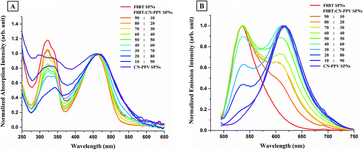 | ||
| Fig. 8 The (A) absorption and (B) emission spectra of F8BT:CN-PPV SPNs, excitation wavelength = 460 nm. The spectra of the individual polymer SPNs are also drawn for comparison. | ||
The emission spectra of F8BTr:CN-PPV SPNs are shown in Fig. 8B. The blending of as little as 10% F8BT with CN-PPV resulted in the appearance of a shoulder on the left of the F8BT:CN-PPV SPNs' spectrum. The emission's peak of the SPNs synthesized from that specific blend was positioned exactly on the peak of CN-PPV SPNs, and its shoulder was positioned exactly where F8BT's emission peak was. Increasing F8BT's ratio and decreasing CN-PPV's ratio resulted in a consequent increase in F8BT's emission intensity and a consequent decrease in CN-PPV's emission intensity, and with F8BT ratios more that 40%, F8BT's emission intensity became dominant and its peak became the main feature. This suggested that there were no inter-chain interactions between both polymers and the increase in the ratio of one resulted in a consequent increase in its emission intensity in the polyblend SPNs.
Experimental
The particles were prepared using the miniemulsion method reported previously,5,16 with some minor modifications to produce aqueous SPNs from a blend of three conjugated polymers with different ratios; two red/orange emitting polymers poly[2-methoxy-5-(2-ethylhexyloxy)-1,4-phenylenevinylene] (MEH-PPV, MW 70![[thin space (1/6-em)]](https://www.rsc.org/images/entities/char_2009.gif) 000–100
000–100![[thin space (1/6-em)]](https://www.rsc.org/images/entities/char_2009.gif) 000, Sigma Aldrich) and poly(2,5-di(hexyloxy)cyanoterephthalylidene) (CN-PPV, MW not stated, Sigma Aldrich), and one green emitting polymer poly(9,9-dioctylfluorene-alt-benzothiadiazole) (F8BT, MW 10,000–20
000, Sigma Aldrich) and poly(2,5-di(hexyloxy)cyanoterephthalylidene) (CN-PPV, MW not stated, Sigma Aldrich), and one green emitting polymer poly(9,9-dioctylfluorene-alt-benzothiadiazole) (F8BT, MW 10,000–20![[thin space (1/6-em)]](https://www.rsc.org/images/entities/char_2009.gif) 000, Sigma Aldrich). The SPNs prepared from the blend of the three polymers were called F8BT:MEH-PPV:CN-PPV SPNs and were prepared with weight ratios (20
000, Sigma Aldrich). The SPNs prepared from the blend of the three polymers were called F8BT:MEH-PPV:CN-PPV SPNs and were prepared with weight ratios (20![[thin space (1/6-em)]](https://www.rsc.org/images/entities/char_2009.gif) :
:![[thin space (1/6-em)]](https://www.rsc.org/images/entities/char_2009.gif) 20
20![[thin space (1/6-em)]](https://www.rsc.org/images/entities/char_2009.gif) :
:![[thin space (1/6-em)]](https://www.rsc.org/images/entities/char_2009.gif) 60), (20
60), (20![[thin space (1/6-em)]](https://www.rsc.org/images/entities/char_2009.gif) :
:![[thin space (1/6-em)]](https://www.rsc.org/images/entities/char_2009.gif) 60
60![[thin space (1/6-em)]](https://www.rsc.org/images/entities/char_2009.gif) :
:![[thin space (1/6-em)]](https://www.rsc.org/images/entities/char_2009.gif) 20), (60
20), (60![[thin space (1/6-em)]](https://www.rsc.org/images/entities/char_2009.gif) :
:![[thin space (1/6-em)]](https://www.rsc.org/images/entities/char_2009.gif) 20
20![[thin space (1/6-em)]](https://www.rsc.org/images/entities/char_2009.gif) :
:![[thin space (1/6-em)]](https://www.rsc.org/images/entities/char_2009.gif) 20) and (30
20) and (30![[thin space (1/6-em)]](https://www.rsc.org/images/entities/char_2009.gif) :
:![[thin space (1/6-em)]](https://www.rsc.org/images/entities/char_2009.gif) 30
30![[thin space (1/6-em)]](https://www.rsc.org/images/entities/char_2009.gif) :
:![[thin space (1/6-em)]](https://www.rsc.org/images/entities/char_2009.gif) 40). SPNs from the individual polymers and from the blends of two of the three polymers were also synthesized for comparison; F8BT SPNs, MEH-PPV SPNs, and CN-PPV SPNs, F8BT:MEH-PPV SPNs, MEH-PPV:CN-PPV SPNs, and F8BT:CN-PPV SPNs. The SPNs synthesized from the blend of two polymers were prepared with nine different polymer weight ratios; (10
40). SPNs from the individual polymers and from the blends of two of the three polymers were also synthesized for comparison; F8BT SPNs, MEH-PPV SPNs, and CN-PPV SPNs, F8BT:MEH-PPV SPNs, MEH-PPV:CN-PPV SPNs, and F8BT:CN-PPV SPNs. The SPNs synthesized from the blend of two polymers were prepared with nine different polymer weight ratios; (10![[thin space (1/6-em)]](https://www.rsc.org/images/entities/char_2009.gif) :
:![[thin space (1/6-em)]](https://www.rsc.org/images/entities/char_2009.gif) 90), (20
90), (20![[thin space (1/6-em)]](https://www.rsc.org/images/entities/char_2009.gif) :
:![[thin space (1/6-em)]](https://www.rsc.org/images/entities/char_2009.gif) 80), (30
80), (30![[thin space (1/6-em)]](https://www.rsc.org/images/entities/char_2009.gif) :
:![[thin space (1/6-em)]](https://www.rsc.org/images/entities/char_2009.gif) 70), (40
70), (40![[thin space (1/6-em)]](https://www.rsc.org/images/entities/char_2009.gif) :
:![[thin space (1/6-em)]](https://www.rsc.org/images/entities/char_2009.gif) 60), (50
60), (50![[thin space (1/6-em)]](https://www.rsc.org/images/entities/char_2009.gif) :
:![[thin space (1/6-em)]](https://www.rsc.org/images/entities/char_2009.gif) 50), (60
50), (60![[thin space (1/6-em)]](https://www.rsc.org/images/entities/char_2009.gif) :
:![[thin space (1/6-em)]](https://www.rsc.org/images/entities/char_2009.gif) 40), (70
40), (70![[thin space (1/6-em)]](https://www.rsc.org/images/entities/char_2009.gif) :
:![[thin space (1/6-em)]](https://www.rsc.org/images/entities/char_2009.gif) 30), (80
30), (80![[thin space (1/6-em)]](https://www.rsc.org/images/entities/char_2009.gif) :
:![[thin space (1/6-em)]](https://www.rsc.org/images/entities/char_2009.gif) 20), and (90
20), and (90![[thin space (1/6-em)]](https://www.rsc.org/images/entities/char_2009.gif) :
:![[thin space (1/6-em)]](https://www.rsc.org/images/entities/char_2009.gif) 10). The four different F8BT:MEH-PPV:CN-PPV SPNs were also compared with four mixtures of the pre-synthesized individual SPNs prepared with percentages equal to their ratios.
10). The four different F8BT:MEH-PPV:CN-PPV SPNs were also compared with four mixtures of the pre-synthesized individual SPNs prepared with percentages equal to their ratios.
In this synthesis, the solvent dichloromethane was substituted with chloroform due to its lower boiling point. The surfactant SDS was used due to its higher emulsion stability when compared to poly-ethylene glycol (PEG), its abundance, ease of transport, and significantly cheaper price compared to phospholipids or other PEG based surfactants despite the fact that SDS is not intended for medical applications.17
In a typical synthesis, 15 mg of each polymer was dissolved in 15 mL chloroform to form polymer stock solutions. In another flask, 43 mg sodium dodecyl sulfate (SDS) was dissolved in 25 mL of ultra-pure water. Then, 1 mL of the polymer stock solution was introduced over a period of 60 seconds, and the emulsion was stirred for 10 minutes, sonicated for 2 minutes at 7 degrees celsius, then stirred gently again for 5 minutes. The milky suspension was then stirred vigorously overnight to ensure the evaporation of the chloroform and formation of the nanoparticles. For the polyblend SPNs; the introduced 1 mL of polymer solution was first prepared by mixing ratios of the polymers, for example, for 20![[thin space (1/6-em)]](https://www.rsc.org/images/entities/char_2009.gif) :
:![[thin space (1/6-em)]](https://www.rsc.org/images/entities/char_2009.gif) 20
20![[thin space (1/6-em)]](https://www.rsc.org/images/entities/char_2009.gif) :
:![[thin space (1/6-em)]](https://www.rsc.org/images/entities/char_2009.gif) 60 F8BT
60 F8BT![[thin space (1/6-em)]](https://www.rsc.org/images/entities/char_2009.gif) :
:![[thin space (1/6-em)]](https://www.rsc.org/images/entities/char_2009.gif) MEH-PPV
MEH-PPV![[thin space (1/6-em)]](https://www.rsc.org/images/entities/char_2009.gif) :
:![[thin space (1/6-em)]](https://www.rsc.org/images/entities/char_2009.gif) CN-PPV SPNs; 400 μL F8BT stock solution, 400 μL MEH-PPV stock solution, and 1200 μL CN-PPV stock solution were mixed and 1 mL of the resulting solution was used in the synthesis.
CN-PPV SPNs; 400 μL F8BT stock solution, 400 μL MEH-PPV stock solution, and 1200 μL CN-PPV stock solution were mixed and 1 mL of the resulting solution was used in the synthesis.
The resultant nanoparticles' shapes and sizes were determined by transmission electron microscopy (TEM, JEM-1011, JEOL), and their optical properties were determined by absorption spectrometry (Thermo Scientific, Genesys 10S UV-Vis Spectrometer) and emission spectrometry (Perkin Elmer Luminescence Spectrometer, LS45).
Conclusions
In conclusion, F8BT:MEH-PPV:CN-PPV SPNs were synthesized and their optical spectra were found to be different than those of mixtures of the individual polymer SPNs due to inter-chain interactions between MEH-PPV and F8BT and between MEH-PPV and CN-PPV. Notably, there were no direct optically observed inter-chain interactions between the chains of F8BT and CN-PPV in terms of emission, however, mixing both polymers in one nanoparticle caused a modification in the particles' UV absorption. With the inclusion of the three polymers within one nanoparticle, multiple inter-chain interactions occurred between MEH-PPV and the other polymers facilitating an indirect interaction between the chains of F8BT and CN-PPV.Conflicts of interest
There are no conflicts to declare.Acknowledgements
We acknowledge Dr Salim M. El-Hamidy, Electronic Microscopy Unit, Biological Science Department, Faculty of Sciences, KAU, for TEM assistance.Notes and references
- Z. Hashim, PhD thesis, King's College London, 2013
.
- P. Howes, M. Green, A. Bowers, D. Parker, G. Varma, M. Kallumadil, M. Hughes, A. Warley, A. Brain and R. Botnar, J. Am. Chem. Soc., 2010, 132, 9833 CrossRef CAS PubMed
.
- J. Pichaandi and F. C. J. M. van Veggel, Coord. Chem. Rev., 2014, 263–264, 138 CrossRef CAS
.
- C. Philippot and P. Reiss, in Frontiers of Nanoscience, ed. M. d. l. F. Jesus and V. Grazu, Elsevier, 2012, vol. 4, p. 81 Search PubMed
.
- Z. Hashim, P. Howes and M. Green, J. Mater. Chem., 2011, 21, 1797 RSC
.
- P. Howes and M. Green, Photochem. Photobiol. Sci., 2010, 9, 1159 CAS
.
- E. Kemal, T. F. Abelha, L. Urbano, R. Peters, D. M. Owen, P. Howes, M. Green and L. A. Dailey, RSC Adv., 2017, 7, 15255 RSC
.
- Y. Q. Ge, Y. Zhang, S. Y. He, F. Nie, G. J. Teng and N. Gu, Nanoscale Res. Lett., 2009, 4, 287–295 CrossRef CAS PubMed
.
- C. F. Wu, H. S. Peng, Y. F. Jiang and J. McNeill, J. Phys. Chem. B, 2006, 110, 14148 CrossRef CAS PubMed
.
- D. Feldman, J. Macromol. Sci., Part A: Pure Appl.Chem., 2015, 52, 648 CrossRef CAS
.
- X. Wang, L. C. Groff and J. D. McNeill, J. Phys. Chem. C, 2014, 118, 25731 CAS
.
- C. F. Huebner, R. D. Roeder and S. H. Foulger, Adv. Funct. Mater., 2009, 19, 3604 CrossRef CAS
.
- H. Yabu, Polym. J., 2013, 45, 261 CrossRef CAS
.
- M.-S. Jang, S.-Y. Song, H.-K. Shim, T. Zyung, S.-D. Jung and L.-M. Do, Synth. Met., 1997, 91, 317 CrossRef CAS
.
- T. Higuchi, A. Tajima, H. Yabu and M. Shimomura, Soft Matter, 2008, 4, 1302 RSC
.
- Z. Hashim, M. Green, P. H. Chung, K. Suhling, A. Protti, A. Phinikaridou, R. Botnar, R. A. Khanbeigi, M. Thanou, L. A. Dailey, N. J. Commander, C. Rowland, J. Scott and D. Jenner, Nanoscale, 2014, 6, 8376 RSC
.
- M. Green, P. Howes, C. Berry, O. Argyros and M. Thanou, Proc. R. Soc. A, 2009, 465, 2751 CrossRef CAS
.
| This journal is © The Royal Society of Chemistry 2017 |

