 Open Access Article
Creative Commons Attribution 3.0 Unported Licence
Arbitrary alignment-angle control method of electrospun fibers: potential for a stretchable electrode material†
Doo-Hyeb Youn *a,
Changbong Yeonac,
Jin Sik Choid,
Nae-Man Parka,
Inyeal Leeb,
Gil-Ho Kimb and
Sun Jin Yun*ac
aElectronics and Telecommunications Research Institute, 138 Gajeongno, Yuseong-gu, Deajeon, 305-700, Korea. E-mail: dhyoun@etri.re.kr; sjyun@etri.re.kr
bSchool of Electronics and Electrical Engineering, Sungkyunkwan Advanced Institute of Nanotechnology (SAINT), Sungkyunkwan University, Suwon 16419, Korea
cDepartment of Advanced Device Engineering, University of Science and Technology, 217 Gajeongno, Yuseong-gu, Daejeon 34113, Korea
dDepartment of Physics, Konkuk University, Seoul 05029, Republic of Korea
First published on 20th September 2017
Abstract
Uniform and reproducible alignment methods for one-dimensional structures, such as wires, tubes, and fibers are essential for the fabrication of commercial devices. This paper presents an arbitrary alignment-angle control method. The mechanical stretching of arbitrarily aligned fibers can be increased by as much as 120%. Stretchable electrodes that stably maintain their electro-optical properties against large mechanical deformations are essential for the fabrication of wearable electronics. For randomly distributed fibers, fiber-to-fiber contact resistance has a detrimental effect on the carrier transport. The proposed method aligns fibers into a uniform array to reduce the fiber-to-fiber contact resistance between fibers using parallel-aligned bars. The results demonstrate the feasibility of applying the transfer-free alignment method along a specific alignment-angle for fabricating stretchable metal fiber networks. Fibers are aligned directly onto the sample surface by mounting the alignment jig onto the conventional collecting plate. This transfer-free strategy avoids the deformation and overlap of aligned patterns during the conventional transferring process.
Introduction
Electrospinning, as a cost-effective and simple method that is capable of fabricating extremely long fibers with a high specific surface area,1–4 has been employed in many applications.5–8 It is known that materials with ordered microstructures and patterns may possess specific functions that are useful in numerous applications, such as microelectronic, photonic, and display applications. For example, well aligned electrospun electrode materials and electron beam evaporated metals have been reported as new materials that can be fabricated with low cost and high scalability for transparent and flexible electrodes.9 And some research groups have reported various flexible and stretchable electrode materials consisting of metal nanowires, CNTs, conductive polymers, and conductive fibers.10–14 Although these electrode materials showed a highly flexible and stretchable performance, there are inevitable drawbacks that need to be solved for the fabrication of commercial devices.Firstly, they demonstrated that fibers were aligned not directly on a substrate but a collecting plate located between the two alignment strips. Therefore, it should be necessary to physically transfer the aligned fibers from collecting plate to the desired substrate to do subsequent device processing. Unfortunately, this extra step of transferring fiber causes significant problems, such as deformation or overlap, and removal of fiber pattern. Secondly, the above electrode materials have the high hetero-junction resistance at the interface of fiber-to-fiber contact regions for practical application. For random fiber networks, fiber-to-fiber contact resistance has detrimental effects on the carrier transport. The high resistance (∼50 ± 20 kΩ □−1) of random fiber webs should be decreased lower than 30 Ω □−1.
In order to solve those drawbacks, firstly, we studied fiber alignment directly on the sample surface without using an additional transfer step. This transfer-free fiber alignment can avoid the pattern deformation or overlap which occurred during the transfer step. Secondly, we designed and used parallel-type alignment bars to align fibers into a uniform array. This uniform array prevents fiber-to-fiber contact resistance.
In this study, we controlled the alignment-angle arbitrarily by rotating the substrate against the parallel alignment bars. Some groups have aligned the electrospun fibers vertically to align bars with uniform array.15–17 Although these fibers well aligned between two alignment bars, they could not control the alignment-angle, for example, 0°, 45°, 60°, and 90°-tilted to parallel alignment bars. We supposed that if we tilted the alignment-angle to 0°, 45°, 60°, and 90°-tilted to alignment bars, the strain applied to the fibers with 0° tilt could be effectively dissipated depending on the alignment angle. Therefore, we observed that the stretch of the fibers with 90° tilt increased up to 120% without cracks. The mechanical stretch of the arbitrarily aligned fibers was dramatically increased against that of ITO or random distributed fiber.
Experimental
Polyvinylalcohol (PVA, Aldrich), a water-soluble polymer, was selected as the electrospinning-polymer material. PVA powder was added to deionized (DI) water and stirred at room temperature for 1 h to prepare the precursor solution 10 weight percent (wt%). To produce the polymer fiber web, a voltage of 20.5 kV was applied between the nozzle tip and the collecting bar using a high-voltage supplier (Tera Leader). Subsequently, the free-standing polymer fiber web was collected on an aluminum bar (diameter of the frame was 30 mm). The free-standing polymer fiber web on the Al collecting bar was then annealed at 150 °C for 10 min to induce welding of individual fibers; this welding process can reduce the height differences at the junctions of the fibers. The density of the polymer fiber web was controlled according to time.After electrospinning of PVA fiber, Al was deposited using an electron beam evaporator at a thickness of 150 nm upon the fiber alignment jig. The first kind of fiber collecting bar was an electrical conductive bar with different designed architectures, such as a parallel or rectangle-shape bar. The alignment processes of metal fiber were conducted as follows. First, PVA was dissolved in DI water uniformly. Second, the alignment-angle of the PVA fibers was controlled using specially designed jigs on a substrate (flexible rubber). Third, the PVA fibers were heated at 150 °C in air for 10 min to remove the heterojunctions between fibers. The structural properties were characterized by SEM (FEI SIRION-400). Electrical characterizations were measured under mechanical strain (stretching) using a Keithley 4200-SCS semiconductor parametric analyzer. Induced strain was calculated using the following equation: stretching strain = (Ls/Lo) × 100 (Ls: length after stretching, Lo: length before stretching). The sheet resistance was measured using a Keithley 4200-SCS semiconductor parameter analyzer.
Results and discussion
1. Alignment jig design
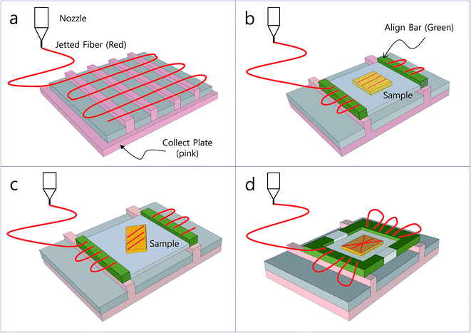
Fig. 1a–d show the schematic setup of the alignment jig used to align fibers with arbitrary direction. The strong electric field between the nozzle tip and collecting plate (pink) points the electrospun fiber (red) from the nozzle tip to the collecting plate (pink) as shown in Fig. 1a. If we place the alignment jig upon the collecting plate at the location of an electrode in the collecting plate (pink), the bars in the alignment jig (green) adjust to the same position (Fig. 1b). The applied field passes from the left bar to the right bar (green) of the alignment jig. Therefore, the fibers jetted from the nozzle tip are guided between a pair alignment bars as shown in Fig. 1b–d. During this process, if we insert the substrate into the sample holder (yellow), the electrospun fibers are collected directly on the sample surface.The alignment jig is composed of two aluminum bars (green) at both the left and right edges with an electrical isolation gap (gray) between the two aluminum bars. The substrate (yellow) is located upon the alignment jig. Fig. 1b and c illustrate the schematic setups used to control the alignment-angle by rotating the substrate. Here the alignment-angles are changed to 0° and 45°-tilted to the direction of parallel alignment bars. In this electrospinning process, Coulomb force plays a very important role to align fibers between two bars. In a pair of bars, the positively charged fibers discharge immediately when they are deposited on the bars randomly. Then, Coulomb force has little effect on the alignment of the fibers. However, between the bars, the as-spun fibers can retain their charges. The oppositely biased electric field of the alignment bars pulls down the positively charged fibers from the upper nozzle tip to below the collecting bar. Here the field strength between the nozzle tip and the left bar is stronger than that of the right bar because the distance between the nozzle and the left bar is shorter than that between the nozzle and the right bar. Therefore, the fibers jetted from the nozzle go from the left bar towards the right bar (Fig. 1b–d).
2. Effects of shapes of alignment jig on fiber alignment
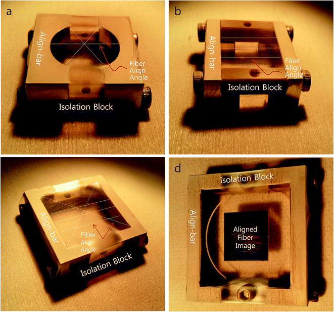
There have been some reports about designing the collecting plate to control fiber distribution.15–17 It was found that the orientation of fibers is strongly dependent on the design of the collecting plate. However, there has been no report about alignment-angle control using specially designed alignment jigs until now. Fig. 1b and d illustrate the schematic setups used to control the alignment-angle using a parallel alignment bar (green in Fig. 1b) and a rectangular alignment jig (green in Fig. 1d). Here the distributions of electrospun fibers show the different shapes as parallel distribution and cross distribution, respectively.Fig. 2a–c are photographic images of various alignment jigs, which have circular, parallel, and rectangular shapes, respectively. The alignment bars at the edges of jigs are separated by insulating blocks between pairs of bars. The electrospinning setup comprises a jet, a collector, and a high-voltage source. When a high voltage is applied to the jet, a droplet of the precursor is elongated to form fibers as shown in Fig. 2a–c. In the figures, the fibers are too thin to distinguish in the pictures. However, if we enlarge the fiber images, as shown in ESI Fig. S1a–d† (corresponds to edge part of alignment jig in Fig. 2b), we can clearly observe the fiber images.
Simultaneously, a pair of alignment bars are used to align fibers connected from left to right alignment bar. The Coulomb force between a pair of alignment bars aligns fibers with circular, parallel, and rectangular orientations as indicated by the white lines in Fig. 2a–c. The electrospun fibers formed by conventional electrospinning, consist of multilayer fibers with a random arrangement. In such a random network, fiber-to-fiber contact resistance has detrimental effects on the carrier transport. To eliminate such fiber-to-fiber contacts, fibers are configured into uniform arrays. As seen in Fig. 2b, the electrospun fibers are in parallel alignment from the left bar to the right bar without fiber-to-fiber contact.
Rogers and others have reported large-area uniform arrays using a transfer method, such as the polydimethylsiloxane (PDMS) stamping method.18 They demonstrated high-performance electronic devices using dense, perfectly aligned arrays of single-walled carbon nanotubes. However, their extra transfer step for aligning synthesized materials (nanowires, nanofibers, etc.) onto the device substrate can cause a number of significant problems, such as pattern deformation, removal, and overlap. It is very important to remove the transfer step for the fabrication of practical devices.
Fig. 2d demonstrates that fibers are aligned directly on sample surface without a transfer step by inserting the substrate between a pair of alignment bars. If the distance between the bars and the substrate is smaller than 3 mm, the electrospun fibers span the bar and substrate. Therefore, it is necessary to disconnect the fibers after fiber alignment. In this disconnection step, the alignment direction of the fibers would be deformed and we could not align the fibers uniaxially. However, if we extend the distance to more than 4 mm, the electrospun fibers disconnect from the left bar and align onto the surface as shown in Fig. 2d. With this configuration, if we rotate the substrate 45° and 90°, the fibers are aligned in 45° and 90°-tilted direction against the applied field direction (Fig. 2d), respectively. Therefore, we can align fibers uniformly and control the alignment-angle as we wish without an additional transfer step.
3. Thermal annealing
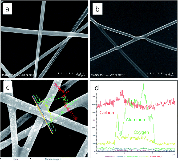
After the electrospinning process, the as-spun fibers are sintered at 150 °C in hotplate for 10 min. Before calcination, two fibers do not form a fused single fiber and are simply touching at the junction as shown in Fig. 3a. After calcination, two fibers at the junction are fused together and form one transport line as shown in Fig. 3b. The diameter of the fibers decreases from ∼350 nm to ∼180 nm due to the evaporation of the carbon and hydrogen components of polyvinylalcohol (PVA). To detect the component elements of electrospun Al fiber, EDS with a large spot size (∼1 μm) was performed as shown in Fig. 3c and d. Fig. 3d shows that the Al-deposited PVA fiber consisted of Al, C, and O.Free-standing fiber webs with uniform array were produced (fiber diameter: ∼350 nm) on a collector by electrospinning (Fig. 2b). After directional deposition of metals (150 nm of Al) onto the upper side of the free-standing fibers, the lower surface (polymer side) of the fiber, where the metal was uncoated, was placed in contact with the desired substrate. In the case of as-spun fibers without calcination, the mean Rs value of the hybrid fibers consisting of Al and PVA ranged 3 ± 2 kΩ □−1. Because charge transport is difficult due to the high potential barrier between fiber-to-fiber contacts. However, in the case of as-spun fibers with calcination at 150 °C in air for 10 min to remove the heterojunctions between fibers, the mean Rs value decreases to 43 ± 15 Ω □−1. The results indicate that the junction resistance between the crossed fibers can be significantly decreased by calcination, which results in improved charge transport. Therefore, the sheet resistance became small.
In the case of the randomly distributed, non-uniform fibers webs consisting of high density and low density regions of fibers caused relatively large deviations in Rs. For example, the mean Rs and standard deviation (SD) values of the fiber webs were ∼50 ± 20 kΩ □−1. However, the uniformly aligned fibers webs with parallel arrays showed small deviations in Rs. For example, the mean Rs and standard deviation (SD) values of the fiber webs were ∼3 ± 2 kΩ □−1. These results clearly demonstrate that the uniformly aligned fibers made using an alignment jig showed decreased mean Rs and significantly improved uniformity. For comparison, the Rs values for the randomly and uniformly aligned fibers are summarized in Table 1. After calcination at 150 °C in air for 10 min, the mean Rs value of the randomly and uniformly aligned fibers further decreased to ∼50 ± 20 kΩ □−1 and ∼43 ± 15 Ω □−1, respectively.
| Fiber align | Rs (before) (Ω □−1) | Rs (after) (Ω □−1) |
|---|---|---|
| Random array | 450 ± 250 kΩ □−1 | 50 ± 20 kΩ □−1 |
| Uniform array | 3 ± 2 kΩ □−1 | 43 ± 15 Ω □−1 |
4. Stretching test
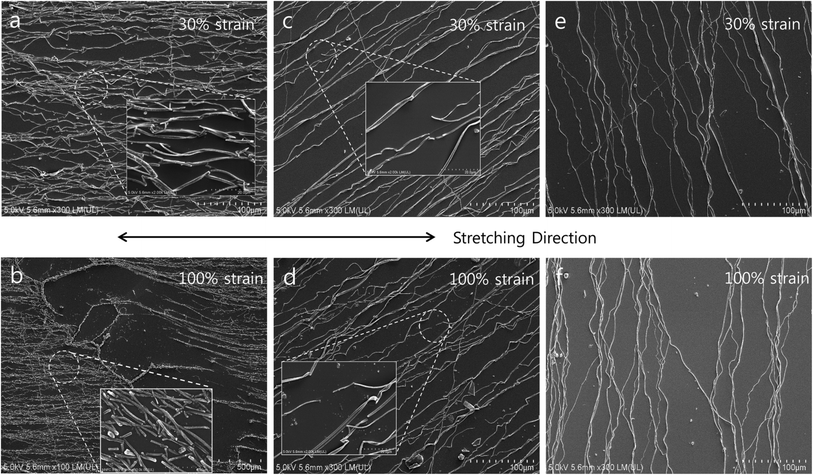
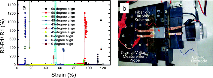
The shapes of the alignment jigs used in the electrospinning step can control the alignment direction of fibers. We supposed that the alignment direction can affect the stretch of a fiber web. For example, parallel-type jigs (Fig. 1b and 2b) in which the electric field is uniformly parallel through the alignment bars can produce parallel alignment (Fig. 4a and b). If we rotate a sample with a 45°-tilted direction to the direction of the biased electric field, the electrospun fibers are aligned in a 45°-tilted direction to the applied field direction as shown in Fig. 4c and d, respectively.To analyze the effects of the alignment-angle on the stretching properties, fibers with three different alignments (0°-tilted, 45°-tilted and 90°-tilted to align-bar) were fabricated as shown in Fig. 4. After these samples were clamped by two fixtures connected to a current–voltage measurement system, they were stretched in specific elongation directions with specific lengths using a mechanical apparatus as shown in Fig. 5b.
Fig. 5a shows the relative resistance change (%) ΔR = R2 − R1 after stretching test. Where the R1 and R2 are the resistances of fiber before and after stretching, respectively. If we stretched the aligned fibers up to 30% in a direction parallel to the applied field, the fibers 0°-tilted to the alignment bar were almost broken due to the applied tensile force as shown in Fig. 4a. However, the fibers with a 45° tilt were partially broken at some locations, almost fibers were not broken (Fig. 4c). And the fibers with a 45° tilt were not broken (Fig. 4e). When the applied tensile force of the fibers with a 0° tilt was increased, the broken fibers were completely separated due to the increased tensile force (Fig. 4b). However, the fibers with a 45° tilt can dissipate the applied tensile force with partially broken fibers as shown in Fig. 4d.
We developed a simple model to describe the current flow of the fibers with a 90° tilt during the stretching test (ESI Fig. S3†). Where the fibers consisted of the fibers with a 90° tilt (indicated by black lines) and fibers that were slightly tilted in a 90° tilt (indicated by red lines).
If strain was applied, the fibers with a 90° tilt were separated mechanically and current could not flow anymore (black line). However, the slightly tilted fibers (red line) interconnected the space between the fibers with a 90° tilt and current flowed through these tilted fibers. Therefore, the fibers with a 90° tilt showed complete electrical connection by these slightly tilted fibers (Fig. 4e and f) although we stretched them up to 120%.
Park et al. reported that randomly distributed fibers made using the metal precursor and a polymer mixed solution showed a limited stretch of less than 10%. They used the vacuum metal deposition method on the surface of electrospun PVA fibers.10 However, we found that the mechanical stretch could be increased up to greater than 120% if we increased the alignment-angle from 0° to 90°.
We observed that the mechanical stretches of angle aligned fibers were 11.5–16.5%, 50.7–64.1%, and 92.8–117.2% (Fig. 5a), respectively. The mechanical stretch of the alignment-angle controlled fibers increased as the alignment-angle was increased from 0° to 90°-tilted to the alignment bar, respectively. The mechanical stretch of the fibers with a 45° tilt against the direction of alignment bar could be stretched up to ∼120% without electrical disconnection as shown in Fig. 6c and d. The pad electrode (inset of Fig. 5b) was peeled-off as the strain increased to more than 120%; thus, the stretch measurement could no longer be continued. The fabrication steps were modified multiple times to avoid the peeling-off of the pad electrode, but this could not be achieved because the adhesion between the pad electrode and silver epoxy (inset of Fig. 5b) was not strong enough to endure mechanical strain greater than 120%. Hence, we assumed that the mechanical stretch of the fibers with a 90° tilt can be increased to more than 120% if we can increase the adhesion between the pad electrode and silver epoxy. This mechanical stretch of metal fiber was dramatically superior to that of ITO, which can be cracked by the application of a tensile strain of ∼1%.
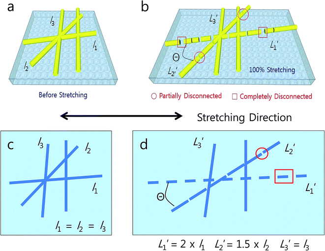
![[thin space (1/6-em)]](https://www.rsc.org/images/entities/char_2009.gif) Θ. Here, l and L′ are the substrate length before and after stretching, respectively. For example, the fibers with a 0° tilt to the alignment direction of alignment bar stretched up to 100%, where cosine 0 = 1 (vertical align), and 100% strain was fully applied to the stretched fibers. Therefore, the stretching length of the fibers with a 90° tilt against alignment bar (Δl1) was doubled compared to that before stretching (L1′ = 2l1). The fibers with a 90° tilt were deformed with complete cracks as shown in Fig. 6b and L1′ in Fig. 6d (indicated by red rectangular box). However, for the 60°-tilted fibers against alignment bar stretched up to 100% where cosine 60 = 0.5, the strain was reduced and only 50% strain was applied. Hence, the 60°-tilted fibers were deformed with partial cracks as shown in Fig. 6b and L2′ in Fig. 6d (indicated by red circle).
Θ. Here, l and L′ are the substrate length before and after stretching, respectively. For example, the fibers with a 0° tilt to the alignment direction of alignment bar stretched up to 100%, where cosine 0 = 1 (vertical align), and 100% strain was fully applied to the stretched fibers. Therefore, the stretching length of the fibers with a 90° tilt against alignment bar (Δl1) was doubled compared to that before stretching (L1′ = 2l1). The fibers with a 90° tilt were deformed with complete cracks as shown in Fig. 6b and L1′ in Fig. 6d (indicated by red rectangular box). However, for the 60°-tilted fibers against alignment bar stretched up to 100% where cosine 60 = 0.5, the strain was reduced and only 50% strain was applied. Hence, the 60°-tilted fibers were deformed with partial cracks as shown in Fig. 6b and L2′ in Fig. 6d (indicated by red circle).If we increased the alignment-angle to be 90° tilted to the alignment bar where cosine 90 = 0, the strain was fully reduced and very small strain was applied. The fibers with a 90° tilt deformed without cracks with complete electrical connection (Fig. 6b and L3′ in Fig. 6d). In fibers with stretching smaller than 30%, irrespective of alignment angle, almost fibers were not disconnected (Fig. 4a, c and e). However, with further stretching up to 100%, fibers with vertical and 45°-tilted aligned fibers disconnected, and these cracked lines became nonconductive sources as shown in L1′ (complete disconnection) and L2′ (partial disconnection) in Fig. 6. These stretchable characteristics of electrospun fibers are advantageous for stretchable optoelectronic devices, such as transistors, sensors, and detectors. Also, the PVA polymer in the backbone of metal fiber can be easily attached to human skin, clothes, and eyeglasses, suggesting substantial potential for measuring the human heartbeat and the temperature of human skin as a strain sensor in wearable electronics.
5. Alignment-angle control of electrospun fibers
In this research, we found that electrospun fibers can be aligned directly onto the sample surface by controlling the distance and height of the substrate from a pair of bars as shown in Fig. 2d. If we separate the distance between the bars and make a sample larger than 4 mm, the electrospun fibers disconnect from the starting bar and align directly onto the sample surface. Here, the heights of the sample were maintained at about 3 mm from the top of the bar pair. The dimensions of the alignment jig were 30 mm (width), 10 mm (height), and 30 mm (length). The dimensions of the electrode were 10 mm (width), 10 mm (height), and 30 mm (length).Fig. 7b and c are scanning electron microscope (SEM) images of the fibers with a 0° tilt and the fibers with a 45° tilt, respectively. Here, we measured the secondary electron microscopic images at the edge of the sample to clarify the alignment direction against the direction of the alignment bar. The electrospinning setup comprised a nozzle, a collecting bar, and a high-voltage source as shown in Fig. 1. When a high voltage was applied between the nozzle and the collecting bar, a droplet of the precursor was elongated into fibers. Two parallel bars were used to align fibers into a parallel direction in comparison to that of the applied bias field as shown in Fig. 7b. From the results shown in Fig. 2d, we found that fibers were aligned directly onto the sample surface. For the parallel-oriented alignment, if we rotated the substrate to be 45°-tilted towards the direction of the alignment bar, the fibers were 45°-tilted as shown in Fig. 7c.
Conclusion
In this paper, we obtained fibers with uniform arrays using parallel-oriented jigs between a pair of bars where the electric field directs the electrospun fiber from the left bar to the right bar. Such uniform fiber arrays show decreased contact resistance of less than 30 Ω □−1. We were able to easily control the alignment-angle to be vertical, 45-tilted, and horizontal to the direction of the alignment bar, respectively, by rotating the sample. The strain applied to the fibers decreased as the rotation angle (angle between the alignment direction of the fiber and the direction of the alignment bars) increased. We could stretch the arbitrarily aligned fibers up to 120% without cracks. The mechanical stretch of the arbitrarily aligned fibers was dramatically increased against that of ITO or random distributed fiber. Thus, these uniformly angle-aligned metal fibers can be used as stretchable electrode materials. We believe this approach presents a promising strategy for developing flexible and stretchable electronic devices, indicating substantial potential for wearable strain, pressure, and temperature sensors for the detection of the pulse of muscles beat and heartbeat (artificial skin). Also, we demonstrated a transfer-free fiber alignment method. Fibers are aligned directly on the sample surface by mounting the alignment jig onto the conventional collecting plate of an electrospinning apparatus. The proposed transfer-free fiber alignment method avoids the pattern deformation or overlap which can occur during the transfer step.Conflicts of interest
There are no conflicts to declare.Acknowledgements
This work was supported by the Institute for Information & Communications Technology Promotion (IITP) grant funded by the Korea government (MSIP) (B0117-16-1003, Fundamental technologies of two-dimensional materials and devices for the platform of new-functional smart devices). The authors would like to thank Professor Jang-Ung Park and his research team members for the fabrication of the hybrid structure of PVA and Al fibers with random distribution at Ulsan National Institute of Science and Technology (UNIST), Ulsan Metropolitan City, 689-798, Republic of Korea, Dr Suck-Gil Han, Sung-Tae Park, Sang-Chul Hyun, and Jin-Young Oh for their cooperation in alignment jig designing and fabrication at Tera Leader Co., and Dr Jae-Bon Goo, and Mrs Bok-Sun Na for the fabrication of the pad electrode and stretching measurements at ETRI.References
- D. Li and Y. N. Xia, Adv. Mater., 2004, 16, 1151–1170 CrossRef CAS.
- Z. M. Huang, Y. Z. Zhang, M. Kotaki and S. Ramakrishna, Compos. Sci. Technol., 2003, 63, 2223–2253 CrossRef CAS.
- N. Huang, S. Patel, R. Thakar, J. Wu, B. Hsiao, B. Chu, R. Lee and S. Li, Nano Lett., 2007, 6, 537–542 CrossRef PubMed.
- H. Wu, J. Fan, C. Chu and J. Wu, J. Mater. Sci.: Mater. Med., 2010, 21, 3207–3215 CrossRef CAS PubMed.
- M. M. Bergshoef and G. J. Vancso, Adv. Mater., 1999, 11, 1362–1365 CrossRef CAS.
- J. Xie and Y. L. Hsieh, J. Mater. Sci., 2003, 38, 2125–2133 CrossRef CAS.
- H. Liu, J. Kameoka, D. A. Czaplewski and H. G. Craighead, Nano Lett., 2004, 4, 671–675 CrossRef CAS.
- H. Yoshimoto, Y. M. Shin, H. Terai and J. P. Vacanti, Biomaterials, 2003, 24, 2077–2082 CrossRef CAS PubMed.
- H. Wu, L. Hu, M. W. Rowell, D. Kong, J. J. Cha, J. R. McDonough, J. Zhu, Y. Yang, M. D. McGehee and Y. Cui, Nano Lett., 2010, 10, 4242–4248 CrossRef CAS PubMed.
- B. W. An, B. G. Hyun, S. Y. Kim, M. J. Kim, M. S. Lee, K. S. Lee, J. B. Koo, Y. Y. Chu, B. S. Bae and J. U. Park, Nano Lett., 2014, 14, 6322–6328 CrossRef CAS PubMed.
- T. Cheng, Y. Zhang, W. Lai and W. Huang, Adv. Mater., 2015, 27, 3349–3376 CrossRef CAS PubMed.
- T. Cheng, Y. Zhang, J. Zhang, W. Lai and W. Huang, J. Mater. Chem. A, 2016, 4, 10493–10499 CAS.
- T. Cheng, Y. J. Yi, Y. Z. Zhang, L. Yang, J. Zhang, W. Lai and W. Huang, J. Mater. Chem. A, 2016, 4, 13754–13763 CAS.
- T. Cheng, Y. Zhang, W. Lai, Y. Chen, W. Zeng and W. Huang, J. Mater. Chem. C, 2014, 2, 10369–10376 RSC.
- D. Li, Y. Wang and Y. Xia, Nano Lett., 2003, 3, 1167–1171 CrossRef CAS.
- D. Zhang and J. Chang, Adv. Mater., 2007, 19, 3664–3667 CrossRef CAS.
- D. Zhang and J. Chang, Nano Lett., 2008, 10, 3283–3287 CrossRef PubMed.
- S. J. Kang, C. K. Kocabas, H. S. Kim, Q. C. Matthew, A. Meitl, D. Y. Khang and A. Rogers, Nano Lett., 2007, 10, 3343–3348 CrossRef PubMed.
Footnote |
| † Electronic supplementary information (ESI) available: Enlarged images of Fig. 2 in order to clarify the images of electrospun fibers; Fig. S1. And SEM measurement data obtained for other sample; Fig. S2. See DOI: 10.1039/c7ra08223a |
| This journal is © The Royal Society of Chemistry 2017 |

