 Open Access Article
Creative Commons Attribution 3.0 Unported Licence
Fabrication of N1-butyl substituted 4,5-dimethyl-imidazole based crosslinked anion exchange membranes for fuel cells
Jinkai Hao ab,
Xueqiang Gaoab,
Yongyi Jiangab,
Feng Xieab,
Zhigang Shao
 *a and
Baolian Yia
aFuel Cell System and Engineering Group, Dalian Institute of Chemical Physics, Chinese Academy of Sciences, 457 Zhongshan Road, 116023 Dalian, PR China. E-mail: zhgshao@dicp.ac.cn; Fax: +86 411 84379185; Tel: +86 411 84379153
bUniversity of Chinese Academy of Sciences, 100049 Beijing, PR China
First published on 15th November 2017
Abstract
Novel N1, C4, C5-substituted imidazolium-based crosslinked anion exchange membranes (AEMs) are prepared by the incorporation of polybenzimidazole (PBI) into the poly(vinylbenzyl chloride) (PVBC) matrix. 1-Butyl-4,5-dimethyl-imidazole (BDIm) with methyl substituents at C4, C5 and long side alkyl substituents at N1 is firstly synthesized to enhance the stability of AEMs by steric hindrance and hyperconjugative effects and characterized by 1H NMR. The effects of crosslinking density of AEMs on the hydroxide conductivity, swelling ratio, thermal stability, oxidative and alkaline stability are evaluated in detail for fuel cell applications. The results reveal that the crosslinking structure between PVBC and PBI plays a vital role in achieving both good mechanical properties and low swelling ratio. Notably, the AEM containing 66.7% PVBC has the highest ionic conductivity of 16.1 mS cm−1 at 20 °C with an IEC of 2.1 mmol g−1. Meanwhile, the AEMs also exhibit excellent oxidative stability in Fenton's reagent for 200 h and alkaline stability in 1 mol L−1 KOH at 60 °C for 480 h. Furthermore, the peak power density of an H2/O2 single fuel cell is up to 54 mW cm−2.
Introduction
Anion exchange membrane fuel cells (AEMFCs) have received more and more attention because of their superiority to proton exchange membrane fuel cells (PEMFCs), especially the use of non-precious metals, fast electrode kinetics and excellent corrosion resistance of metal materials under basic conditions and so on.1–4 As a key component in an AEMFC, the anion exchange membrane (AEM) faces a trade-off between ionic conductivity, mechanical strength and chemical stability,3,5 which is more serious than that in proton exchange membranes owing to the inherently lower conductivity of OH− (the conductivity ratio of H+/OH− is about 1.76 (ref. 6)) and easy degradation of quaternary ammonium (QA) cationic groups.7It is well known that the balance between chemical stability and ionic conductivity of AEMs is mainly reliant on the structure of AEMs, ion exchange capacity (IEC) and types of functional groups.8 High IEC always leads to a better hydration hydroxyl network for Grotthuss transport,9 but concurrently leads to high water uptake, severe swelling and poor strength.8 To conquer this trade-off, many strategies have been put forward to improve both high ionic conductivity, dimensional and mechanical stability, such as crosslinking3,5,10 and self-aggregation strategy.11 Several researchers have found that crosslinking by introducing chemical or physical cross-links in the system is an effective way to enhance the dimensional stability without separation of the different components.12 Lu et al. reported PVBC/PBI (poly(vinylbenzyl chloride)/polybenzimidazole) crosslinked AEM which exhibited a high conductivity of 25 mS cm−1 at 30 °C with a lower swelling ratio of 13%.3 Lai et al. prepared the phenolphthalein-containing poly(arylene ether sulfone)s crosslinked AEMs showed a high IEC of 1.91 mmol g−1 while the swelling ratio was less than 15%.13 Unfortunately, it has been reported that the aryl ether-containing crosslinked AEMs, such as poly(phenylene oxide) (PPO)14,15 and polysulfone (PSF),16,17 would be severely degraded by cleavage of the C–O bonds via ether hydrolysis and/or QA group hydrolysis under high pH conditions.18,19
Besides, except from the ionic conductivity of AEMs, chemical stability, especially for functional groups, is still considered to be a tough challenge.8 QA20 is most widely used in AEMs and shows great influences on hydroxide conductivity. However, QA groups exhibit different alkaline stabilities when attached to different polymer backbones, such as PPO, poly(arylene ether sulfone) (PAES), and PSF, mainly attribute to the degradation via Hofmann elimination and/or nucleophilic substitution reaction through β-hydrogens.8,21 Various cationic functional groups are the widely used to improve the stability of AEMs, such as imidazolium,1,8 highly alkaline phosphonium,22,23 guanidine24 and so on. Among them, imidazolium functional groups which have a p-conjugated imidazole ring can reduce the reactions of the SN2 substitution, Hofmann elimination reactions and/or ylide formation25 and have been the topic of extensive research in the past few years.2,26–28
However, experimental evidences have indicated that imidazolium functional groups face considerable alkaline degradation when grafted directly to polymer backbones.25 By selecting the appropriate substituents, the degradation of imidazolium functional groups can be inhibited to some extent.20,25 Recently, most of researches are all focus on the stability investigation of the C2-substituted imidazolium cations via the analysis of 1H NMR to small molecule compounds1,26 and have been suggested that steric interference at C2 position has a significant impact on the improvement of stability.28 However, most studies show C2-substituted imidazolium cations still exist the problems of degradation by OH− attacks.26 Varcoe et al. recently reported that the conductivity and IEC of the 1,2-dimethylimidazolium-based AEMs would degrade greatly in 1 M KOH at 60 °C (ref. 29) and the same results are found by Yang25 which found the conductivity of 1,2-dimethylimidazolium functionalized styrene polymeric AEMs would diminish in 1 M KOH at 60 °C after 100 h. Besides, recent researches reported the N1-alkyl and C2-substituted imidazolium cations to further improve the stability of AEMs.25 Density functional theory (DFT) calculations by Pivovar30 or others31–33 predict the positive influence of C4, C5 substituents of imidazolium. Nowadays, Coates and co-workers27 systematically evaluated the small imidazolium molecules with different substitution on N1, N2, C2, C4, C5 position. They confirmed that C4 and C5 methyl substituted imidazolium exhibited the highest alkaline stability and the residual conductivity was higher than 99% after the exposure to 5 M KOH at 80 °C for 30 days.27 They also found that C4, 5 substitution with methyl groups slightly improving the stability relative to phenyl groups and long chain alkyl substituents on N1 position had a more favorable influence on preventing degradation of imidazolium better than benzyl or methyl groups,27 which was agree with the results obtained by Zhang34 and Yan.35 Unfortunately, the influence of C4, C5 substituents on the stability of imidazolium functional AEMs is not too much and deep research. Thus it is necessary for functional groups with high stability to be located on a more stable backbone of polymers under high pH condition in AEMFCs.7
Herein, a novel N1-butyl substituted 4,5-dimethyl-imidazole (BDIm) is synthesized with the purpose to improve the stability of AEMs by steric hindrance and (or) hyperconjugative effects. Using the novel BDIm, we prepared a series of poly(vinylbenzyl chloride) (PVBC)/polybenzimidazole (PBI) crosslinked AEMs containing BDIm groups with high alkaline-resistant and dimension stability. The influences of the crosslinked structure between backbone polymers and BDIm on physical and chemical properties are investigated in detail. Besides, the corresponding membrane is fabricated to the membrane electrode assembly (MEA) and is tested in a single AEMFC.
Experimental
Materials
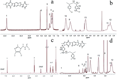
4,5-Dimethyl-1H-imidazole hydrochloride (DIm) was purchased from Wuhan Taikaisai Scientific Co., China. Butyl bromide was purchased from Sigma-Aldrich. Polybenzimidazole (PBI, the inherent viscosity of 2.43 dL g−1 (ref. 36)) was synthesized by the method mentioned in our previous works36 and identified by 1H NMR in DMSO-d6 (Fig. 2a). Poly vinylbenzyl chloride (PVBC, 60/40 mixture of 3- and 4-isomers with average molecular weight Mn ∼55![[thin space (1/6-em)]](https://www.rsc.org/images/entities/char_2009.gif) 000, average Mw ∼100
000, average Mw ∼100![[thin space (1/6-em)]](https://www.rsc.org/images/entities/char_2009.gif) 000 by GPC/MALLS, powder) was procured from Aldrich and identified by 1H NMR in DMSO-d6 (Fig. 2b). Sodium hydride (60% w/w in mineral oil) was purchased from Aladdin Industrial Inc. And N,N-dimethylformamide (DMF), N-methyl-2-pyrrolidone (NMP), ethyl acetate (EtOAc) and other chemicals were commercially available with analytical grade. Besides, the electrocatalyst used in the fuel cell testing was Pt/C (70% Pt on Vulcan XC-72 carbon) and 60% PtRu/C, which was supplied from Johnson Matthey Co. Deionized (DI) water was used in the experiments.
000 by GPC/MALLS, powder) was procured from Aldrich and identified by 1H NMR in DMSO-d6 (Fig. 2b). Sodium hydride (60% w/w in mineral oil) was purchased from Aladdin Industrial Inc. And N,N-dimethylformamide (DMF), N-methyl-2-pyrrolidone (NMP), ethyl acetate (EtOAc) and other chemicals were commercially available with analytical grade. Besides, the electrocatalyst used in the fuel cell testing was Pt/C (70% Pt on Vulcan XC-72 carbon) and 60% PtRu/C, which was supplied from Johnson Matthey Co. Deionized (DI) water was used in the experiments.
Synthesis of 1-butyl-4,5-dimethyl-imidazole (BDIm)
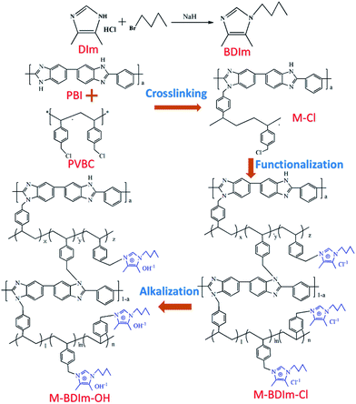
BDIm was synthesized by DIm and butyl bromide via a modified way referred to literature.37,38 Typically, 2 g (0.015 mol) DIm was dissolved in 10 mL DMF at 0 °C, and then 1.44 g (2.4 times the molar amount of DIm) sodium hydride was slowly added into the solution. After heating at 0 °C for 0.5 h under stirring, 3.08 g (0.023 mol) butyl bromide was added in the above solution and was stirred for 3 h at room temperature. The solution mixture was separated by precipitation the mixture in DI water, followed by thorough extracting with ethyl acetate several times. Finally, the crude products were purified by the column chromatography method with EtOAc as the separation agent to obtain the desired BDIm. The synthetic routes are shown in Fig. 1.Preparation of BDIm functionalized membranes
The preparation procedure of the BDIm functionalized PVBC membranes crosslinked by PBI were synthesized by the nucleophilic substitution reaction. The membranes were prepared by two steps as shown in Fig. 1, including preparation of PVBC membranes crosslinked by PBI and functionalization. Briefly, PBI was completely dissolved in the NMP followed by adding PVBC with the mass ratio of PBI and PVBC of 1![[thin space (1/6-em)]](https://www.rsc.org/images/entities/char_2009.gif) :
:![[thin space (1/6-em)]](https://www.rsc.org/images/entities/char_2009.gif) 1, 3
1, 3![[thin space (1/6-em)]](https://www.rsc.org/images/entities/char_2009.gif) :
:![[thin space (1/6-em)]](https://www.rsc.org/images/entities/char_2009.gif) 2, 2
2, 2![[thin space (1/6-em)]](https://www.rsc.org/images/entities/char_2009.gif) :
:![[thin space (1/6-em)]](https://www.rsc.org/images/entities/char_2009.gif) 1 and 3
1 and 3![[thin space (1/6-em)]](https://www.rsc.org/images/entities/char_2009.gif) :
:![[thin space (1/6-em)]](https://www.rsc.org/images/entities/char_2009.gif) 1. After complete dissolution, the mixed polymer solution were cast on a glass plate and dried on a hot plate at 80 °C. In first 24 h, a glass cover was covered on the solution to slow down the evaporation rate to make the crosslinking to react thoroughly. After 24 h, the glass cover was taken away and the solution was dried at 80 °C in the air for 24 h. The PVBC membranes crosslinked by PBI obtained was denoted as M-Cl-x
1. After complete dissolution, the mixed polymer solution were cast on a glass plate and dried on a hot plate at 80 °C. In first 24 h, a glass cover was covered on the solution to slow down the evaporation rate to make the crosslinking to react thoroughly. After 24 h, the glass cover was taken away and the solution was dried at 80 °C in the air for 24 h. The PVBC membranes crosslinked by PBI obtained was denoted as M-Cl-x![[thin space (1/6-em)]](https://www.rsc.org/images/entities/char_2009.gif) :
:![[thin space (1/6-em)]](https://www.rsc.org/images/entities/char_2009.gif) y (x
y (x![[thin space (1/6-em)]](https://www.rsc.org/images/entities/char_2009.gif) :
:![[thin space (1/6-em)]](https://www.rsc.org/images/entities/char_2009.gif) y was the mass ratio of PBI and PVBC of 1
y was the mass ratio of PBI and PVBC of 1![[thin space (1/6-em)]](https://www.rsc.org/images/entities/char_2009.gif) :
:![[thin space (1/6-em)]](https://www.rsc.org/images/entities/char_2009.gif) 1, 3
1, 3![[thin space (1/6-em)]](https://www.rsc.org/images/entities/char_2009.gif) :
:![[thin space (1/6-em)]](https://www.rsc.org/images/entities/char_2009.gif) 2, 2
2, 2![[thin space (1/6-em)]](https://www.rsc.org/images/entities/char_2009.gif) :
:![[thin space (1/6-em)]](https://www.rsc.org/images/entities/char_2009.gif) 1 and 3
1 and 3![[thin space (1/6-em)]](https://www.rsc.org/images/entities/char_2009.gif) :
:![[thin space (1/6-em)]](https://www.rsc.org/images/entities/char_2009.gif) 1). Subsequently, to make the –CH2Cl groups be converted into imidazolium groups, the M-Cl-x
1). Subsequently, to make the –CH2Cl groups be converted into imidazolium groups, the M-Cl-x![[thin space (1/6-em)]](https://www.rsc.org/images/entities/char_2009.gif) :
:![[thin space (1/6-em)]](https://www.rsc.org/images/entities/char_2009.gif) y were functionalized by immersing in 0.5 mol L−1 BDIm ethanol solution for 48 h at 60 °C, named as M-BDIm–Cl-x
y were functionalized by immersing in 0.5 mol L−1 BDIm ethanol solution for 48 h at 60 °C, named as M-BDIm–Cl-x![[thin space (1/6-em)]](https://www.rsc.org/images/entities/char_2009.gif) :
:![[thin space (1/6-em)]](https://www.rsc.org/images/entities/char_2009.gif) y. After that, the membranes in OH− form were obtained by soaking the M-BDIm–Cl-x
y. After that, the membranes in OH− form were obtained by soaking the M-BDIm–Cl-x![[thin space (1/6-em)]](https://www.rsc.org/images/entities/char_2009.gif) :
:![[thin space (1/6-em)]](https://www.rsc.org/images/entities/char_2009.gif) y in 1 mol L−1 KOH solution at room temperature for two days, converting the membranes from the Cl− form into the OH form (M-BDIm–OH-x
y in 1 mol L−1 KOH solution at room temperature for two days, converting the membranes from the Cl− form into the OH form (M-BDIm–OH-x![[thin space (1/6-em)]](https://www.rsc.org/images/entities/char_2009.gif) :
:![[thin space (1/6-em)]](https://www.rsc.org/images/entities/char_2009.gif) y). Then, the membranes were taken out from the alkaline liquor and washed by DI water several times and storing in DI water to remove the residual KOH prior to further experiments. Besides, the thickness of the M-BDIm–OH membranes were about 25 μm.
y). Then, the membranes were taken out from the alkaline liquor and washed by DI water several times and storing in DI water to remove the residual KOH prior to further experiments. Besides, the thickness of the M-BDIm–OH membranes were about 25 μm.
Structure characterization
The 1H NMR spectra were carried out on Bruker Avance III 400 NMR spectrometer, using deuterated dimethylsulfoxide (DMSO-d6) as the solvent and tetramethylsilane (TMS) as the internal standard. Fourier-transform infrared (FT-IR) of M-BDIm–Cl and M-BDIm–OH membranes were recorded at a resolution of 4 cm−1 with a Bruker Equinox 55 FT-IR spectrometer after drying at 60 °C under vacuum overnight. The morphology of the surface and cross-section of the membrane samples were recorded with the field emission scanning electron microscope (FESEM, Zeiss JEM-2100F). And the elemental analysis of samples was conducted by Oxford Inca EDX detector equipped on the FESEM. Before examination, to distinguish the covalently bonded Cl with Cl− ions of M-BDIm–Cl-1![[thin space (1/6-em)]](https://www.rsc.org/images/entities/char_2009.gif) :
:![[thin space (1/6-em)]](https://www.rsc.org/images/entities/char_2009.gif) 1, the samples were carried out after exchanging Cl− with Br− ions and fractured with liquid N2 and then sprayed with gold. The mechanical properties of the dry membranes in the OH− form were characterized by the electrical universal test machine (Changchun Kexin Co., China) at a speed of 5 mm min−1. The thermal stability of the membranes was investigated on a thermogravimetric analyser (DSC-Q1000, USA) with a heating rate of 10 °C min−1 in a temperature range from room temperature to 700 °C under nitrogen atmosphere.
1, the samples were carried out after exchanging Cl− with Br− ions and fractured with liquid N2 and then sprayed with gold. The mechanical properties of the dry membranes in the OH− form were characterized by the electrical universal test machine (Changchun Kexin Co., China) at a speed of 5 mm min−1. The thermal stability of the membranes was investigated on a thermogravimetric analyser (DSC-Q1000, USA) with a heating rate of 10 °C min−1 in a temperature range from room temperature to 700 °C under nitrogen atmosphere.
Ionic exchange capacity (IEC), water uptake (WU) and swelling ratio (SR)
The IEC of membrane samples were determined by the classical back titration method.3,5 Firstly, the membranes in OH− form were dried at 50 °C under vacuum for 48 h. The membranes were immersed in HCl solution for 72 h in order to make sure that all the OH− ions of the membranes were transmuted into H1+ ions. After that, the residual H1+ ions were back titrated with a back titrated method using 0.01 mol L−1 NaOH solution in the presence of an indicator (phenolphthalein). And then the membrane was immersed in DI water and dried in a vacuum at 60 °C for 24 h to achieve a certain weight. And the IEC (mmol g−1) of the membranes was calculated as follows:where Mb,HCl and Ma,HCl were the amount of HCl in mmol before and after titration with NaOH, respectively; and m was the weight of the dried membranes.
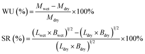
To investigate the WU and SR of the membranes as a function of temperature (20–80 °C), pieces of the membranes were immersed in DI water and equilibrated at each temperature. Equilibrated membranes were wiped quickly with tissue paper to remove water on the surface, and then, measured the mass, width, and length of the fully hydrated membranes. The mass, width, and length of the dry membrane were determined after drying in a vacuum oven at 50 °C for 48 h. The WU and SR of membranes were calculated by equations:
Membrane conductivity measurement
The conductivity of the membranes was measured under fully hydrated condition by a two-probe AC impedance method using a cell with a pair of pressure-attached copper electrodes by a Solartron 1260 & 1287 electrochemical workstation under the potentiostatic mode.3 The measurement was conducted in a frequency range from 106 to 100 Hz at a voltage amplitude of 10 mV in the DI water with N2 saturated. To minimize the influence of CO2, the membranes in OH− form were immersing into DI water with N2 saturated at various temperatures ranging from 20 to 80 °C in a chamber. The conductivity values (σ, mS cm−1) was calculated by the following equation:36,39where L (cm) was the distance between the two electrodes, R was the membrane resistance by the impedance value at 0 phase angle, d and w were the thickness and width of the membrane, respectively.
Membrane durability studies
The long-term alkaline stability of M-BDIm–OH-1![[thin space (1/6-em)]](https://www.rsc.org/images/entities/char_2009.gif) :
:![[thin space (1/6-em)]](https://www.rsc.org/images/entities/char_2009.gif) 1 membrane was evaluated by immersing the membrane in 1 mol L−1 KOH at 60 °C to determine the change in the hydroxide conductivity, dimension and IEC values of the membranes. The hydroxide conductivity of the membrane was measured at 30 °C by the method mentioned above at a certain time interval.
1 membrane was evaluated by immersing the membrane in 1 mol L−1 KOH at 60 °C to determine the change in the hydroxide conductivity, dimension and IEC values of the membranes. The hydroxide conductivity of the membrane was measured at 30 °C by the method mentioned above at a certain time interval.
The oxidative stability of the M-BDIm–OH membranes was evaluated by soaking the membrane in Fenton's reagent. The membrane was dried and weighed, and then soaked into 30 mL Fenton (3 wt% H2O2, 4 ppm Fe2+) solution at 40 °C. Fenton solution was refreshed every 24 hours, and the degraded samples were measured on an electronic balance after absorbing the superficial liquid with filter paper. For comparison, a pure PBI membrane was fabricated and tested by the same method.
Membrane electrode assembly (MEA) and single cell performance
The performances of M-BDIm–OH-1![[thin space (1/6-em)]](https://www.rsc.org/images/entities/char_2009.gif) :
:![[thin space (1/6-em)]](https://www.rsc.org/images/entities/char_2009.gif) 1 membrane were further evaluated in a single AEMFC. Two gas diffusion electrode (GDE) and membrane with effective area 5 cm2 were pressed at room temperature to form the membrane electrode assembly (MEA). And the PtRu/C (60%, JM Co.) loading of the anode and Pt/C (70%, JM Co.) loading of the cathode were both 0.4 mg cm−2, respectively. Fuel cell tests were estimated under the operating temperature of 50 °C with hydrogen and oxygen gas for both anode and cathode feeds at 0.1 MPa with 100/200 mL min−1, respectively. The polarization curves of AAEMFCs were evaluated by an electric load system (KMF2030, Kikusui Electronics Corp.) and Solartron 1260 workstation. The EIS experiments were carried out at a current between 10 mA to 500 mA with a small amplitude alternating voltage of 10 mV and the frequency range was from 10 kHz to 0.1 Hz.
1 membrane were further evaluated in a single AEMFC. Two gas diffusion electrode (GDE) and membrane with effective area 5 cm2 were pressed at room temperature to form the membrane electrode assembly (MEA). And the PtRu/C (60%, JM Co.) loading of the anode and Pt/C (70%, JM Co.) loading of the cathode were both 0.4 mg cm−2, respectively. Fuel cell tests were estimated under the operating temperature of 50 °C with hydrogen and oxygen gas for both anode and cathode feeds at 0.1 MPa with 100/200 mL min−1, respectively. The polarization curves of AAEMFCs were evaluated by an electric load system (KMF2030, Kikusui Electronics Corp.) and Solartron 1260 workstation. The EIS experiments were carried out at a current between 10 mA to 500 mA with a small amplitude alternating voltage of 10 mV and the frequency range was from 10 kHz to 0.1 Hz.
Results and discussion
Preparation and structure analysis of the BDIm functionalized crosslinked membranes
4,5-Dimethyl-1H-imidazole hydrochloride (DIm) was reacted with butyl bromide to synthesize the BDIm and purified by the column chromatography. The structure of the as-synthesized BDIm is shown in Fig. 1. As confirmed by 1H NMR analysis in Fig. 2c, the signal at 2.01, 2.07 ppm are ascribed to methyl at C4, C5 and the H3–H5 are correspond to protons of butyl. The well-defined peaks indicate that the successful synthesis of BDIm. The overall synthetic procedure for M-BDIm–OH was mainly divided into three parts, involving the preparation of PVBC membranes crosslinked by PBI, BDIm functionalization and alkalization, as shown in Fig. 1.PBI, with good mechanical properties and thermal stabilities, is used as a macromolecular crosslinker to interconnect with PVBC. So to identify the crosslinking reaction, PBI and PVBC were dissolved in DMSO-d6 and heated for 12 h, and then, recorded in 1H NMR (Fig. 2d). Compared with 1H NMR of PBI (Fig. 2a) and PVBC (Fig. 2b), the new peak at 3.35 of 8 (marked in Fig. 2d) can confirmed the crosslinking reaction of M-Cl, which is agree with the results obtained by our previous works.3 So a series of M-Cl are prepared with the mass ratio of PBI and PVBC of 1![[thin space (1/6-em)]](https://www.rsc.org/images/entities/char_2009.gif) :
:![[thin space (1/6-em)]](https://www.rsc.org/images/entities/char_2009.gif) 1, 3
1, 3![[thin space (1/6-em)]](https://www.rsc.org/images/entities/char_2009.gif) :
:![[thin space (1/6-em)]](https://www.rsc.org/images/entities/char_2009.gif) 2, 2
2, 2![[thin space (1/6-em)]](https://www.rsc.org/images/entities/char_2009.gif) :
:![[thin space (1/6-em)]](https://www.rsc.org/images/entities/char_2009.gif) 1 and 3
1 and 3![[thin space (1/6-em)]](https://www.rsc.org/images/entities/char_2009.gif) :
:![[thin space (1/6-em)]](https://www.rsc.org/images/entities/char_2009.gif) 1. Subsequently, to make the –CH2Cl groups be converted into imidazolium groups, M-Cl was functionalized by immersing in 0.5 mol L−1 BDIm ethanol solution for 48 h at 60 °C, named as M-BDIm–Cl and followed by converting into the OH− form (M-BDIm–OH). The basic parameters of M-BDIm–OH with different ratio is shown in Table 1 and the overall synthetic procedure for the AEMs is illustrated in Fig. 1.
1. Subsequently, to make the –CH2Cl groups be converted into imidazolium groups, M-Cl was functionalized by immersing in 0.5 mol L−1 BDIm ethanol solution for 48 h at 60 °C, named as M-BDIm–Cl and followed by converting into the OH− form (M-BDIm–OH). The basic parameters of M-BDIm–OH with different ratio is shown in Table 1 and the overall synthetic procedure for the AEMs is illustrated in Fig. 1.
| Samples | PBI![[thin space (1/6-em)]](https://www.rsc.org/images/entities/char_2009.gif) : :![[thin space (1/6-em)]](https://www.rsc.org/images/entities/char_2009.gif) PVBC molar ratio PVBC molar ratio |
IEC (mmol g−1) | σa (mS cm−1) | WUa (%) | SRa (%) | Tensile strength (MPa) | Elongation at break (%) |
|---|---|---|---|---|---|---|---|
| a Measured at room temperature (20 °C). | |||||||
M-BDIm–OH-1![[thin space (1/6-em)]](https://www.rsc.org/images/entities/char_2009.gif) : :![[thin space (1/6-em)]](https://www.rsc.org/images/entities/char_2009.gif) 1 1 |
0.5![[thin space (1/6-em)]](https://www.rsc.org/images/entities/char_2009.gif) : :![[thin space (1/6-em)]](https://www.rsc.org/images/entities/char_2009.gif) 1 1 |
2.10 | 16.1@20 °C | 6.0 | 13.9 | 87.6 | 4.8 |
| 19.2@30 °C | |||||||
M-BDIm–OH-3![[thin space (1/6-em)]](https://www.rsc.org/images/entities/char_2009.gif) : :![[thin space (1/6-em)]](https://www.rsc.org/images/entities/char_2009.gif) 2 2 |
0.75![[thin space (1/6-em)]](https://www.rsc.org/images/entities/char_2009.gif) : :![[thin space (1/6-em)]](https://www.rsc.org/images/entities/char_2009.gif) 1 1 |
1.80 | 13.5@20 °C | 3.7 | 9.3 | 98.7 | 6.0 |
| 15.4@30 °C | |||||||
M-BDIm–OH-2![[thin space (1/6-em)]](https://www.rsc.org/images/entities/char_2009.gif) : :![[thin space (1/6-em)]](https://www.rsc.org/images/entities/char_2009.gif) 1 1 |
1![[thin space (1/6-em)]](https://www.rsc.org/images/entities/char_2009.gif) : :![[thin space (1/6-em)]](https://www.rsc.org/images/entities/char_2009.gif) 1 1 |
1.48 | 11.2@20 °C | 0.8 | 6.1 | 110.7 | 7.1 |
| 13.0@30 °C | |||||||
M-BDIm–OH-3![[thin space (1/6-em)]](https://www.rsc.org/images/entities/char_2009.gif) : :![[thin space (1/6-em)]](https://www.rsc.org/images/entities/char_2009.gif) 1 1 |
1.5![[thin space (1/6-em)]](https://www.rsc.org/images/entities/char_2009.gif) : :![[thin space (1/6-em)]](https://www.rsc.org/images/entities/char_2009.gif) 1 1 |
1.40 | 7.9@20 °C | 0.5 | 4.3 | 122.6 | 10.0 |
| 9.3@30 °C | |||||||
Due to the insolubility of M-BDIm–OH, the chemical structures of M-Cl-1![[thin space (1/6-em)]](https://www.rsc.org/images/entities/char_2009.gif) :
:![[thin space (1/6-em)]](https://www.rsc.org/images/entities/char_2009.gif) 1, M-BDIm–Cl-1
1, M-BDIm–Cl-1![[thin space (1/6-em)]](https://www.rsc.org/images/entities/char_2009.gif) :
:![[thin space (1/6-em)]](https://www.rsc.org/images/entities/char_2009.gif) 1 and M-BDIm–OH-1
1 and M-BDIm–OH-1![[thin space (1/6-em)]](https://www.rsc.org/images/entities/char_2009.gif) :
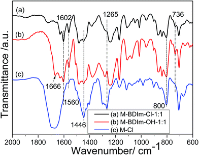
:![[thin space (1/6-em)]](https://www.rsc.org/images/entities/char_2009.gif) 1 were characterized by FT-IR, shown in Fig. 3. The FT-IR spectrum of M-Cl-1
1 were characterized by FT-IR, shown in Fig. 3. The FT-IR spectrum of M-Cl-1![[thin space (1/6-em)]](https://www.rsc.org/images/entities/char_2009.gif) :
:![[thin space (1/6-em)]](https://www.rsc.org/images/entities/char_2009.gif) 1 exhibited the characteristic absorption bands at 1265 cm−1 is attributed to stretching vibrations of unreacted CH2–Cl groups of PVBC.40 And the peaks at 800 cm−1, 1666 cm−1 and 1446 cm−1, which are assigned to the stretch vibration in plane of C
1 exhibited the characteristic absorption bands at 1265 cm−1 is attributed to stretching vibrations of unreacted CH2–Cl groups of PVBC.40 And the peaks at 800 cm−1, 1666 cm−1 and 1446 cm−1, which are assigned to the stretch vibration in plane of C![[double bond, length as m-dash]](https://www.rsc.org/images/entities/char_e001.gif) C and C
C and C![[double bond, length as m-dash]](https://www.rsc.org/images/entities/char_e001.gif) N groups, can be ascribed to the existence of PBI.36
N groups, can be ascribed to the existence of PBI.36
Compared with M-Cl-1![[thin space (1/6-em)]](https://www.rsc.org/images/entities/char_2009.gif) :
:![[thin space (1/6-em)]](https://www.rsc.org/images/entities/char_2009.gif) 1, BDIm is introduced confirmed by the disappearance of the absorption peak at 1265 cm−1 in M-BDIm–Cl-1
1, BDIm is introduced confirmed by the disappearance of the absorption peak at 1265 cm−1 in M-BDIm–Cl-1![[thin space (1/6-em)]](https://www.rsc.org/images/entities/char_2009.gif) :
:![[thin space (1/6-em)]](https://www.rsc.org/images/entities/char_2009.gif) 1 and M-BDIm–OH-1
1 and M-BDIm–OH-1![[thin space (1/6-em)]](https://www.rsc.org/images/entities/char_2009.gif) :
:![[thin space (1/6-em)]](https://www.rsc.org/images/entities/char_2009.gif) 1. And the peak at about 736 cm−1 in M-BDIm–Cl-1
1. And the peak at about 736 cm−1 in M-BDIm–Cl-1![[thin space (1/6-em)]](https://www.rsc.org/images/entities/char_2009.gif) :
:![[thin space (1/6-em)]](https://www.rsc.org/images/entities/char_2009.gif) 1 and M-BDIm–OH-1
1 and M-BDIm–OH-1![[thin space (1/6-em)]](https://www.rsc.org/images/entities/char_2009.gif) :
:![[thin space (1/6-em)]](https://www.rsc.org/images/entities/char_2009.gif) 1 is assigned to the vibration of C–N bond in imidazolium cations.7,20 Besides, the strong absorption bands near 1560 cm−1 and 1602 cm−1 are mainly ascribed to the stretching vibration of the C–H of butyl. All these differences of FT-IR spectral data definitely confirm the successful introduction of BDIm into M-Cl-1
1 is assigned to the vibration of C–N bond in imidazolium cations.7,20 Besides, the strong absorption bands near 1560 cm−1 and 1602 cm−1 are mainly ascribed to the stretching vibration of the C–H of butyl. All these differences of FT-IR spectral data definitely confirm the successful introduction of BDIm into M-Cl-1![[thin space (1/6-em)]](https://www.rsc.org/images/entities/char_2009.gif) :
:![[thin space (1/6-em)]](https://www.rsc.org/images/entities/char_2009.gif) 1.
1.
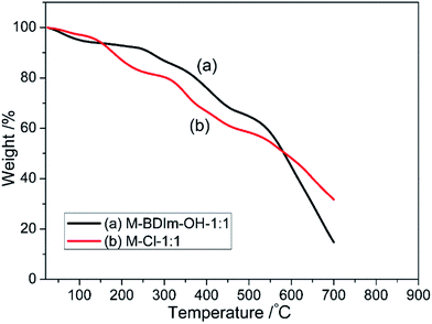
The thermal degradation behaviour of the M-BDIm–Cl-1![[thin space (1/6-em)]](https://www.rsc.org/images/entities/char_2009.gif) :
:![[thin space (1/6-em)]](https://www.rsc.org/images/entities/char_2009.gif) 1 and M-Cl-1
1 and M-Cl-1![[thin space (1/6-em)]](https://www.rsc.org/images/entities/char_2009.gif) :
:![[thin space (1/6-em)]](https://www.rsc.org/images/entities/char_2009.gif) 1 were examined via thermogravimetric analysis (TGA) under a nitrogen atmosphere, shown in Fig. 4. We all know that PBI and PVBC exhibit excellent thermomechanical stability up to ∼600 °C and ∼350 °C which is mentioned by our previous works.3
1 were examined via thermogravimetric analysis (TGA) under a nitrogen atmosphere, shown in Fig. 4. We all know that PBI and PVBC exhibit excellent thermomechanical stability up to ∼600 °C and ∼350 °C which is mentioned by our previous works.3
In the TG curves of M-BDIm–Cl-1![[thin space (1/6-em)]](https://www.rsc.org/images/entities/char_2009.gif) :
:![[thin space (1/6-em)]](https://www.rsc.org/images/entities/char_2009.gif) 1 and M-Cl-1
1 and M-Cl-1![[thin space (1/6-em)]](https://www.rsc.org/images/entities/char_2009.gif) :
:![[thin space (1/6-em)]](https://www.rsc.org/images/entities/char_2009.gif) 1, the weight loss before 150 °C may due to bonded water and residual solvent, which is followed by a new weight loss step. The new weight loss from 150 °C to 200 °C is probably due to the degradation of crosslinking point formed between PBI and –CH2–Cl groups.3 In the TG curve of M-BDIm–Cl-1
1, the weight loss before 150 °C may due to bonded water and residual solvent, which is followed by a new weight loss step. The new weight loss from 150 °C to 200 °C is probably due to the degradation of crosslinking point formed between PBI and –CH2–Cl groups.3 In the TG curve of M-BDIm–Cl-1![[thin space (1/6-em)]](https://www.rsc.org/images/entities/char_2009.gif) :
:![[thin space (1/6-em)]](https://www.rsc.org/images/entities/char_2009.gif) 1, the new step from 210 °C to 370 °C can be attribute to the decomposition to BDIm cations and butyl. And the decomposition of main-chain of PVBC takes place above 450 °C.3 In summary, the M-BDIm–Cl crosslinked membrane exhibits better thermomechanical stability at the operating temperature of AEMFC (50–60 °C).
1, the new step from 210 °C to 370 °C can be attribute to the decomposition to BDIm cations and butyl. And the decomposition of main-chain of PVBC takes place above 450 °C.3 In summary, the M-BDIm–Cl crosslinked membrane exhibits better thermomechanical stability at the operating temperature of AEMFC (50–60 °C).
Morphology of the M-BDIm–OH crosslinked membranes
The surface and cross-section FESEM images of the M-BDIm–OH-1![[thin space (1/6-em)]](https://www.rsc.org/images/entities/char_2009.gif) :
:![[thin space (1/6-em)]](https://www.rsc.org/images/entities/char_2009.gif) 1 are presented in Fig. 5e–g. M-BDIm–OH-1
1 are presented in Fig. 5e–g. M-BDIm–OH-1![[thin space (1/6-em)]](https://www.rsc.org/images/entities/char_2009.gif) :
:![[thin space (1/6-em)]](https://www.rsc.org/images/entities/char_2009.gif) 1 shows a uniform and homogeneous morphology and the cross-section of M-BDIm–OH-1
1 shows a uniform and homogeneous morphology and the cross-section of M-BDIm–OH-1![[thin space (1/6-em)]](https://www.rsc.org/images/entities/char_2009.gif) :
:![[thin space (1/6-em)]](https://www.rsc.org/images/entities/char_2009.gif) 1 reveals the formation of a compact and faultless structure with the thickness of about 25 μm. In fact, the apparent separation may occur for the AEMs with different components, which can bring the negative effect on the mechanical properties or the ability of ionic conduction.5 And in order to confirm the adequacy of functionalization of BDIm, the Cl elements distribution of M-BDIm–Cl-1
1 reveals the formation of a compact and faultless structure with the thickness of about 25 μm. In fact, the apparent separation may occur for the AEMs with different components, which can bring the negative effect on the mechanical properties or the ability of ionic conduction.5 And in order to confirm the adequacy of functionalization of BDIm, the Cl elements distribution of M-BDIm–Cl-1![[thin space (1/6-em)]](https://www.rsc.org/images/entities/char_2009.gif) :
:![[thin space (1/6-em)]](https://www.rsc.org/images/entities/char_2009.gif) 1 were record by EDX. Before examination, the Cl− ions of M-BDIm–Cl-1
1 were record by EDX. Before examination, the Cl− ions of M-BDIm–Cl-1![[thin space (1/6-em)]](https://www.rsc.org/images/entities/char_2009.gif) :
:![[thin space (1/6-em)]](https://www.rsc.org/images/entities/char_2009.gif) 1 was exchanged to Br−. From the EDX in Fig. 5a and b, we can see that the content of covalently bonded Cl reduce from 75.93% to 0.5%. It reveals the sufficient conversion of –CH2Cl to –CH2BDIm. And the uniform and homogeneous morphology exhibited in M-Cl-1
1 was exchanged to Br−. From the EDX in Fig. 5a and b, we can see that the content of covalently bonded Cl reduce from 75.93% to 0.5%. It reveals the sufficient conversion of –CH2Cl to –CH2BDIm. And the uniform and homogeneous morphology exhibited in M-Cl-1![[thin space (1/6-em)]](https://www.rsc.org/images/entities/char_2009.gif) :
:![[thin space (1/6-em)]](https://www.rsc.org/images/entities/char_2009.gif) 1 can confirm the successful formation of the crosslinking structure because that lack of interaction between different components will cause the phase separation.3
1 can confirm the successful formation of the crosslinking structure because that lack of interaction between different components will cause the phase separation.3
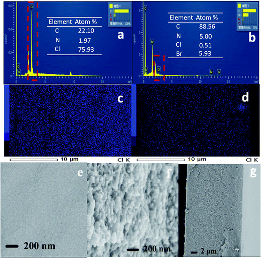 | ||
Fig. 5 EDX spectra of (a) M-Cl-1![[thin space (1/6-em)]](https://www.rsc.org/images/entities/char_2009.gif) : :![[thin space (1/6-em)]](https://www.rsc.org/images/entities/char_2009.gif) 1 and (b) M-BDIm–Br-1 1 and (b) M-BDIm–Br-1![[thin space (1/6-em)]](https://www.rsc.org/images/entities/char_2009.gif) : :![[thin space (1/6-em)]](https://www.rsc.org/images/entities/char_2009.gif) 1; the Cl elements distribution of (c) M-Cl-1 1; the Cl elements distribution of (c) M-Cl-1![[thin space (1/6-em)]](https://www.rsc.org/images/entities/char_2009.gif) : :![[thin space (1/6-em)]](https://www.rsc.org/images/entities/char_2009.gif) 1 and (d) M-BDIm–Br-1 1 and (d) M-BDIm–Br-1![[thin space (1/6-em)]](https://www.rsc.org/images/entities/char_2009.gif) : :![[thin space (1/6-em)]](https://www.rsc.org/images/entities/char_2009.gif) 1; surface (e) and cross-sectional (f, g) SEM images of M-BDIm–OH-1 1; surface (e) and cross-sectional (f, g) SEM images of M-BDIm–OH-1![[thin space (1/6-em)]](https://www.rsc.org/images/entities/char_2009.gif) : :![[thin space (1/6-em)]](https://www.rsc.org/images/entities/char_2009.gif) 1. 1. | ||
Analysis of IEC, water uptake (WU) and swelling ratio (SR)
The IEC, WU, SR and ionic conductivity of M-BDIm–OH are shown in Table 1. IEC value reflects the fixed ion concentration in AEMs and can reflects the properties of AEMs to some extent.25,41 The IEC values of M-BDIm–OH were obtained by the back titration method. As shown in Fig. 6a and Table 1, it can be seen that with increasing PVBC mole content from 40% to 67%, the IEC ranges from 1.20 to 2.10 mmol g−1 because of the increment of BDIm cation groups in the AEMs. The WU and SR of AEMs are equally important parameters and show the same trend in different PVBC/PBI mole proportions. Moderate WU is benefit to ion migration, but high WU of AEMs is normally accompanied by over swelling and mechanical weakness. Fortunately, we can see that moderate WU is obtained in M-BDIm–OH which is benefit from the crosslinking structure of PBI and PVBC. As listed in Table 1, WU increases from 0.5% to 6.0% at room temperature as a result of increments of ionic groups, and SR also follow the same trend. SR of M-BDIm–OH-1![[thin space (1/6-em)]](https://www.rsc.org/images/entities/char_2009.gif) :
:![[thin space (1/6-em)]](https://www.rsc.org/images/entities/char_2009.gif) 1 is only 13.9%, which is much lower than other uncrosslinked AEMs listed in Table 2. The more incorporation of PBI is sought to improve the crosslinking density and rigidity of M-BDIm–OH, resulting in a lower WU and SR, and hence having a higher dimensional stability. Furthermore, WU and SR of M-BDIm–OH under different temperatures are measured and shown in Fig. 6b and c. We can see that the WU and SR of M-BDIm–OH nearly do not grow vigorously in water under elevated temperature between 20 °C to 80 °C, which is attribute to the crosslinking of PVBC/PBI. Therefore, M-BDIm–OH provides a potential prospect in development of AEMs with good dimensional stability.
1 is only 13.9%, which is much lower than other uncrosslinked AEMs listed in Table 2. The more incorporation of PBI is sought to improve the crosslinking density and rigidity of M-BDIm–OH, resulting in a lower WU and SR, and hence having a higher dimensional stability. Furthermore, WU and SR of M-BDIm–OH under different temperatures are measured and shown in Fig. 6b and c. We can see that the WU and SR of M-BDIm–OH nearly do not grow vigorously in water under elevated temperature between 20 °C to 80 °C, which is attribute to the crosslinking of PVBC/PBI. Therefore, M-BDIm–OH provides a potential prospect in development of AEMs with good dimensional stability.
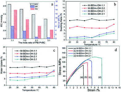 | ||
Fig. 6 The IEC, SR and WU of the M-BDIm–OH with different mole ratio of PBI![[thin space (1/6-em)]](https://www.rsc.org/images/entities/char_2009.gif) : :![[thin space (1/6-em)]](https://www.rsc.org/images/entities/char_2009.gif) PVBC (a); the changes of SR (b) and WU (c) at a function of temperature; stress versus strain curves for M-BDIm–OH (d). PVBC (a); the changes of SR (b) and WU (c) at a function of temperature; stress versus strain curves for M-BDIm–OH (d). | ||
| Membrane | IEC (mmol g−1) | σ (mS cm−1) | WUa (%) | SRa (%) | Tensile strength (MPa) | Peak power density (mW cm−2) | Ref. |
|---|---|---|---|---|---|---|---|
| a Measured at room temperature (20 °C).b [DAMIm][Br] is 1,3-diallyl-2-methyl imidazolium bromine and PSAN is the mixture polymers of styrene, acrylonitrile and benzoin ethyl ether.c C12VIMBr is vinyl based polymer with 3-n-alkyl-1-vinylimidazolium bromide.d PPO-COC5H10-Im is poly(2,6-dimethyl-1,4-phenylene oxide) with imidazolium-terminated long side chains.e Measured at 60 °C.f PAEK/UnIm0.1MeIm0.9 is poly(aryl ether ketone) with UnIm and MeIm.g 1.50-PAEK-QM is poly(arylene ether ketone) with N1-MeIm.h PSf135-ImOH is polysulfone with methylimidazole. | |||||||
M-BDIm–OH-1![[thin space (1/6-em)]](https://www.rsc.org/images/entities/char_2009.gif) : :![[thin space (1/6-em)]](https://www.rsc.org/images/entities/char_2009.gif) 1 1 |
2.10 | 16.1@20 °C | 6.0 | 13.9 | 87.6 | 54 | This works |
| 19.2@30 °C | |||||||
| PSAN-[DAMIm][Br]b | 1.31 | 11.3@30 °C | 95.8 | 32.4 | — | — | 28 |
| PVBC/PVA-Im | 1.86 | 21.9@30 °C | 39.4 | 28.6 | 16 | 37.1 | 20 |
| C12VIMBrc | 1.27 | 10.4@20 °C | 17.1 | 7.57 | — | — | 42 |
| PPO-COC5H10-Imd | 1.15 | 25@20 °C | 50e | 15e | 20 | — | 43 |
| PAEK/UnIm0.1MeIm0.9f | 1.00 | 9@25 °C | 68.4 | 53.4 | — | — | 44 |
| 1.50-PAEK-QMg | 2.17 | 6.7@25 °C | 10.1 | — | 59.6 | — | 45 |
| PSf135-ImOHh | 2.46 | 20.7@20 °C | 92.8 | 25.5 | — | 16 | 46 |
Mechanical properties
The comparison of mechanical properties of M-BDIm–OH with different PVBC/PBI compositions are shown in Fig. 6d and Table 1. The tensile strength of 87.6 MPa with elongation at break of 4.8% was obtained in M-BDIm–OH-1![[thin space (1/6-em)]](https://www.rsc.org/images/entities/char_2009.gif) :
:![[thin space (1/6-em)]](https://www.rsc.org/images/entities/char_2009.gif) 1. With the increase of the content of PBI, the tensile strength and elongation of the membranes increase and reach a maximum value of 122.6 MPa and 10.0% for M-BDIm–OH-3
1. With the increase of the content of PBI, the tensile strength and elongation of the membranes increase and reach a maximum value of 122.6 MPa and 10.0% for M-BDIm–OH-3![[thin space (1/6-em)]](https://www.rsc.org/images/entities/char_2009.gif) :
:![[thin space (1/6-em)]](https://www.rsc.org/images/entities/char_2009.gif) 1, respectively. We can see that M-BDIm–OH presents the excellent toughness compared with the homogeneous membranes without crosslinking3 and much higher than reported AEMs.20
1, respectively. We can see that M-BDIm–OH presents the excellent toughness compared with the homogeneous membranes without crosslinking3 and much higher than reported AEMs.20
Hydroxide conductivity
Fig. 7a shows hydroxide conductivity of M-BDIm–OH under different temperatures. In order to minimize the influence of CO2 at various temperatures, the measurement was conducted in the DI water with N2 saturated. We can see that the hydroxide conductivity of M-BDIm–OH is proportional to the IEC and increases from 11.18 to 16.1 mS cm−1 at 20 °C with increasing IEC form 1.48 to 2.10 mmol g−1. The temperature has a positive effect on hydroxide conductivity because of increasing free volume which is benefit to ion transport at higher temperature.20 M-BDIm–OH-1![[thin space (1/6-em)]](https://www.rsc.org/images/entities/char_2009.gif) :
:![[thin space (1/6-em)]](https://www.rsc.org/images/entities/char_2009.gif) 1 exhibits the highest conductivity of 30.8 mS cm−1 at 60 °C, which is meet the conductivity requirement of AEMFCs.5 The conductivity of BDIm–OH-1
1 exhibits the highest conductivity of 30.8 mS cm−1 at 60 °C, which is meet the conductivity requirement of AEMFCs.5 The conductivity of BDIm–OH-1![[thin space (1/6-em)]](https://www.rsc.org/images/entities/char_2009.gif) :
:![[thin space (1/6-em)]](https://www.rsc.org/images/entities/char_2009.gif) 1 at 20 and 30 °C reaches 16.1 and 19.2 mS cm−1, which is similar with the other AEMs in the literature, but the SR of M-BDIm–OH-1
1 at 20 and 30 °C reaches 16.1 and 19.2 mS cm−1, which is similar with the other AEMs in the literature, but the SR of M-BDIm–OH-1![[thin space (1/6-em)]](https://www.rsc.org/images/entities/char_2009.gif) :
:![[thin space (1/6-em)]](https://www.rsc.org/images/entities/char_2009.gif) 1 is much lower than other AEMs listed in Table 2. It should mentioned that the hydroxide conductivity of M-BDIm–OH-1
1 is much lower than other AEMs listed in Table 2. It should mentioned that the hydroxide conductivity of M-BDIm–OH-1![[thin space (1/6-em)]](https://www.rsc.org/images/entities/char_2009.gif) :
:![[thin space (1/6-em)]](https://www.rsc.org/images/entities/char_2009.gif) 1 is higher than PVA/PDDA crosslinked membranes of 11.0 mS cm−1 with 76% WU47 or other AEMs.20 But excessive crosslinker content results in the decreasing of hydroxide conductivity due to impose restriction on the mobility of polymer main chain.48 What is more, M-BDIm–OH-3
1 is higher than PVA/PDDA crosslinked membranes of 11.0 mS cm−1 with 76% WU47 or other AEMs.20 But excessive crosslinker content results in the decreasing of hydroxide conductivity due to impose restriction on the mobility of polymer main chain.48 What is more, M-BDIm–OH-3![[thin space (1/6-em)]](https://www.rsc.org/images/entities/char_2009.gif) :
:![[thin space (1/6-em)]](https://www.rsc.org/images/entities/char_2009.gif) 1 possess the lowest WU resulting in the lowest hydroxide conductivity and indicates that fewer water molecules is benefit to hydroxide transport.20 Besides, as plotted in Fig. 7b, the hydroxide conductivity of M-BDIm–OH follows an approximate Arrhenius behaviour. The calculated activation energy (Ea) of M-BDIm–OH varies from 14.5 to 19.3 kJ mol−1, which is comparable with other reported AEMs.3,49
1 possess the lowest WU resulting in the lowest hydroxide conductivity and indicates that fewer water molecules is benefit to hydroxide transport.20 Besides, as plotted in Fig. 7b, the hydroxide conductivity of M-BDIm–OH follows an approximate Arrhenius behaviour. The calculated activation energy (Ea) of M-BDIm–OH varies from 14.5 to 19.3 kJ mol−1, which is comparable with other reported AEMs.3,49
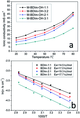 | ||
| Fig. 7 Hydroxide conductivity of M-BDIm–OH as a function of temperature (a) and Arrhenius plots of M-BDIm–OH at different temperatures (b). | ||
Chemical stability
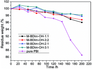
The oxidative stability and long-term alkaline stability of AEM can reflect directly the stability among functional groups and polymers.3,25 The mass loss of the M-BDIm–OH was tested in Fenton's reagent and the PBI membrane was also tested for comparison, shown in Fig. 8. We can see that the M-BDIm–OH exhibit an acceptable oxidative stability within 200 h compared with pure PBI, which is benefit from the crosslinking structure. With the increasing of crosslinker, the oxidative stability of the M-BDIm–OH improves. Besides, in the first 60 h, the mass of M-BDIm–OH increases mainly due to the degradation at the aromatic and hydrocarbon backbone under oxidative environment.3The same functional groups induced into different polymer backbone may exhibit different alkaline stability. So, the alkaline stability of the M-BDIm–OH-1![[thin space (1/6-em)]](https://www.rsc.org/images/entities/char_2009.gif) :
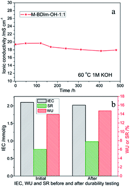
:![[thin space (1/6-em)]](https://www.rsc.org/images/entities/char_2009.gif) 1 was evaluated by immersing into 1 mol L−1 KOH at 60 °C to simulate real environment of AEMFC. From Fig. 9a and Table 3, we can see that the conductivity values, WU and SR of M-BDIm–OH-1
1 was evaluated by immersing into 1 mol L−1 KOH at 60 °C to simulate real environment of AEMFC. From Fig. 9a and Table 3, we can see that the conductivity values, WU and SR of M-BDIm–OH-1![[thin space (1/6-em)]](https://www.rsc.org/images/entities/char_2009.gif) :
:![[thin space (1/6-em)]](https://www.rsc.org/images/entities/char_2009.gif) 1 have not a sharp decline within 480 h and only 7.4% conductivity degradation occur during the whole examination process. And IEC values exhibit less than 5% degradation. The good chemical stability of AEMs depends on the stability of both polymer backbones and functional groups. For polymer backbones, PBI and PVBC contain no ether-based main chain which will be degrade severely in KOH solution at high temperature due to the hydrolysis and quaternary carbon hydrolysis.25–28 And a tight-binding structure is formed by the crosslinking between PBI and PVBC, which has good durability in the high pH environment.3 On the other hand, BDIm is used into the PBI/PVBC polymer backbones, with introduced by substitution at the N1, C4, and C5 positions. It is believed that C4, 5 substitution with methyl groups slightly improves the stability by steric hindrance and (or) hyperconjugative effects. And long chain alkyl substituents on N1 position have a more favorable influence on preventing degradation of imidazolium better than benzyl or methyl groups.27,34,35 So the obtained membranes achieved a better alkaline stability. It can concluded that the M-BDIm–OH AEMs exhibit an acceptable alkaline and oxidative stability.
1 have not a sharp decline within 480 h and only 7.4% conductivity degradation occur during the whole examination process. And IEC values exhibit less than 5% degradation. The good chemical stability of AEMs depends on the stability of both polymer backbones and functional groups. For polymer backbones, PBI and PVBC contain no ether-based main chain which will be degrade severely in KOH solution at high temperature due to the hydrolysis and quaternary carbon hydrolysis.25–28 And a tight-binding structure is formed by the crosslinking between PBI and PVBC, which has good durability in the high pH environment.3 On the other hand, BDIm is used into the PBI/PVBC polymer backbones, with introduced by substitution at the N1, C4, and C5 positions. It is believed that C4, 5 substitution with methyl groups slightly improves the stability by steric hindrance and (or) hyperconjugative effects. And long chain alkyl substituents on N1 position have a more favorable influence on preventing degradation of imidazolium better than benzyl or methyl groups.27,34,35 So the obtained membranes achieved a better alkaline stability. It can concluded that the M-BDIm–OH AEMs exhibit an acceptable alkaline and oxidative stability.
Single cell performance
The M-BDIm–OH-1![[thin space (1/6-em)]](https://www.rsc.org/images/entities/char_2009.gif) :
:![[thin space (1/6-em)]](https://www.rsc.org/images/entities/char_2009.gif) 1 shows good physicochemical properties, like good stability, excellent conductivity and good mechanical properties. So M-BDIm–OH-1
1 shows good physicochemical properties, like good stability, excellent conductivity and good mechanical properties. So M-BDIm–OH-1![[thin space (1/6-em)]](https://www.rsc.org/images/entities/char_2009.gif) :
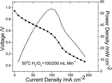
:![[thin space (1/6-em)]](https://www.rsc.org/images/entities/char_2009.gif) 1 was used for single cell and the polarization curve and power density curve are shown in Fig. 10. The open circuit potential (OCV) is 0.944 V and it indicates that the obtained membrane has good gas barrier property of AEMs which is more favorable electrochemical reaction kinetics under high pH condition.20,50 And the peak power density of the MEA is 54 mW cm−2 at 0.549 V, and is comparable with other AEMs listed in Table 2. Besides, to improve the performance of the AEMFCs, great efforts should be focused on several factors, such as the surface activity of the electrode and the compatibility, the architecture of catalyst layer with good three-phase boundary, MEA fabrication procedure and so on.
1 was used for single cell and the polarization curve and power density curve are shown in Fig. 10. The open circuit potential (OCV) is 0.944 V and it indicates that the obtained membrane has good gas barrier property of AEMs which is more favorable electrochemical reaction kinetics under high pH condition.20,50 And the peak power density of the MEA is 54 mW cm−2 at 0.549 V, and is comparable with other AEMs listed in Table 2. Besides, to improve the performance of the AEMFCs, great efforts should be focused on several factors, such as the surface activity of the electrode and the compatibility, the architecture of catalyst layer with good three-phase boundary, MEA fabrication procedure and so on.
Conclusions
A series of the homogeneous crosslinked PVBC/PBI membranes with 1-butyl-4,5-dimethyl-imidazole (BDIm) were prepared and evaluated as AEMs for fuel cells. BDIm with methyl substituents at C4, C5 and long side alkyl substituents at N1 is firstly synthetized and can greatly enhance the stability by steric hindrance and hyper-conjugative effects resulting in the good alkaline stability of AEMs. The crosslinking structure between PVBC and PBI plays a vital role in achieving both good mechanical, dimension and chemical properties. The M-BDIm–OH-1![[thin space (1/6-em)]](https://www.rsc.org/images/entities/char_2009.gif) :
:![[thin space (1/6-em)]](https://www.rsc.org/images/entities/char_2009.gif) 1 is tuned to be an optimal AEM and displays desirable performance with the ionic conductivity of 16.1 mS cm−1 at 20 °C, SR of 13.9% and tensile stress of 87.6 MPa. Meanwhile, M-BDIm–OH both has good oxidative stability in Fenton's reagent for 200 h and has good alkaline stability with only 7.4% conductivity degradation in 1 mol L−1 KOH at 60 °C for 480 h, indicating that the obtained AEMs can fulfill the basic conductivity requirement for AEMFCs. The MEA assembled with the optimized M-BDIm–OH-1
1 is tuned to be an optimal AEM and displays desirable performance with the ionic conductivity of 16.1 mS cm−1 at 20 °C, SR of 13.9% and tensile stress of 87.6 MPa. Meanwhile, M-BDIm–OH both has good oxidative stability in Fenton's reagent for 200 h and has good alkaline stability with only 7.4% conductivity degradation in 1 mol L−1 KOH at 60 °C for 480 h, indicating that the obtained AEMs can fulfill the basic conductivity requirement for AEMFCs. The MEA assembled with the optimized M-BDIm–OH-1![[thin space (1/6-em)]](https://www.rsc.org/images/entities/char_2009.gif) :
:![[thin space (1/6-em)]](https://www.rsc.org/images/entities/char_2009.gif) 1 shows the peak power density of 54 mW cm−2 at 0.549 V. Thus, based on the above results, the developed N1-butyl substituted BDIm functionalized PBI/PVBC crosslinked AEMs would be a promising candidate material for fuel cell applications.
1 shows the peak power density of 54 mW cm−2 at 0.549 V. Thus, based on the above results, the developed N1-butyl substituted BDIm functionalized PBI/PVBC crosslinked AEMs would be a promising candidate material for fuel cell applications.
Conflicts of interest
There are no conflicts to declare.Acknowledgements
This work was financially supported by the National Key Research and Development Program of China (No. 2016YFB0101208), the National Natural Science Foundation of China (No. U1508202), innovation Program of Key Laboratory of Fuel Cells and Hybrid Power Sources, CAS (No. KLFC201604), CAS-DOE Cooperation Project (No. 121421KYSB20160009), Flanders (FWO) for a fellowship (12F5514N), a Research Grant (1529816N) and a travel grant (V410316N) for a Visiting Professorship at the Technical University of Denmark.References
- J. Wang, S. Gu, R. B. Kaspar, B. Zhang and Y. Yan, ChemSusChem, 2013, 6, 2079–2082 CrossRef CAS PubMed.
- O. D. Thomas, K. J. W. Y. Soo, T. J. Peckham, M. P. Kulkarni and S. Holdcroft, J. Am. Chem. Soc., 2012, 134, 10753–10756 CrossRef CAS PubMed.
- W. Lu, G. Zhang, J. Li, J. Hao, F. Wei, W. Li, J. Zhang, Z.-G. Shao and B. Yi, J. Power Sources, 2015, 296, 204–214 CrossRef CAS.
- H. Takaba, T. Hisabe, T. Shimizu and M. K. Alam, J. Membr. Sci., 2017, 522, 237–244 CrossRef CAS.
- W. Lu, Z.-G. Shao, G. Zhang, Y. Zhao and B. Yi, J. Power Sources, 2014, 248, 905–914 CrossRef CAS.
- Q. Li, L. Liu, Q. Miao, B. Jin and R. Bai, Chem. Commun., 2014, 50, 2791–2793 RSC.
- X. Qiu, M. Ueda, Y. Fang, S. Chen, Z. Hu, X. Zhang and L. Wang, Polym. Chem., 2016, 7, 5988–5995 RSC.
- X. Gong, X. Yan, T. Li, X. Wu, W. Chen, S. Huang, Y. Wu, D. Zhen and G. He, J. Membr. Sci., 2017, 523, 216–224 CrossRef CAS.
- K. N. Grew and W. K. S. Chiu, J. Electrochem. Soc., 2010, 157, B327–B337 CrossRef CAS.
- J. Zhang, H. Liu, H. Liu, J. Hu, S. Tan and T. Wu, Polym. Bull., 2016, 74, 625–639 CrossRef.
- J. Zheng, Q. Zhang, H. Qian, B. Xue, S. Li and S. Zhang, J. Membr. Sci., 2017, 522, 159–167 CrossRef CAS.
- X. Lin, Y. Liu, S. D. Poynton, A. L. Ong, J. R. Varcoe, L. Wu, Y. Li, X. Liang, Q. Li and T. Xu, J. Power Sources, 2013, 233, 259–268 CrossRef CAS.
- A. N. Lai, D. Guo, C. X. Lin, Q. G. Zhang, A. M. Zhu, M. L. Ye and Q. L. Liu, J. Power Sources, 2016, 327, 56–66 CrossRef CAS.
- M. I. Khan, C. Zheng, A. N. Mondal, M. M. Hossain, B. Wu, K. Emmanuel, L. Wu and T. Xu, Desalination, 2017, 402, 10–18 CrossRef CAS.
- Y. Liu, B. Zhang, C. L. Kinsinger, Y. Yang, S. Seifert, Y. Yan, C. Mark Maupin, M. W. Liberatore and A. M. Herring, J. Membr. Sci., 2016, 506, 50–59 CrossRef CAS.
- J. Pan, C. Chen, L. Zhuang and J. Lu, Acc. Chem. Res., 2012, 45, 473–481 CrossRef CAS PubMed.
- J. Han, H. Peng, J. Pan, L. Wei, G. Li, C. Chen, L. Xiao, J. Lu and L. Zhuang, ACS Appl. Mater. Interfaces, 2013, 5, 13405–13411 CAS.
- C. Fujimoto, D.-S. Kim, M. Hibbs, D. Wrobleski and Y. S. Kim, J. Membr. Sci., 2012, 423, 438–449 CrossRef.
- C. Yang, S. Wang, W. Ma, S. Zhao, Z. Xu and G. Sun, J. Mater. Chem. A, 2016, 4, 3886–3892 CAS.
- D. Guo, Y. Z. Zhuo, A. N. Lai, Q. G. Zhang, A. M. Zhu and Q. L. Liu, J. Membr. Sci., 2016, 518, 295–304 CrossRef CAS.
- J. R. Varcoe and R. C. T. Slade, Fuel Cells, 2005, 5, 187–200 CrossRef CAS.
- B. Zhang, R. B. Kaspar, S. Gu, J. Wang, Z. Zhuang and Y. Yan, ChemSusChem, 2016, 9, 2374–2379 CrossRef CAS PubMed.
- C. T. Womble, G. W. Coates, K. Matyjaszewski and K. J. T. Noonan, ACS Macro Lett., 2016, 5, 253–257 CrossRef CAS.
- T. A. Sherazi, S. Zahoor, R. Raza, A. J. Shaikh, S. A. R. Naqvi, G. Abbas, Y. Khan and S. Li, Int. J. Hydrogen Energy, 2015, 40, 786–796 CrossRef CAS.
- C. Yang, S. Wang, W. Ma, L. Jiang and G. Sun, J. Mater. Chem. A, 2015, 3, 8559–8565 CAS.
- R. Tsuchitani, H. Nakanishi, H. Shishitani, S. Yamaguchi, H. Tanaka and H. Kasai, Solid State Ionics, 2015, 278, 5–10 CrossRef CAS.
- K. M. Hugar, H. A. Kostalik and G. W. Coates, J. Am. Chem. Soc., 2015, 137, 8730–8737 CrossRef CAS PubMed.
- B. Lin, F. Chu, Y. Ren, B. Jia, N. Yuan, H. Shang, T. Feng, Y. Zhu and J. Ding, J. Power Sources, 2014, 266, 186–192 CrossRef CAS.
- O. M. M. Page, S. D. Poynton, S. Murphy, A. L. Ong, D. M. Hillman, C. A. Hancock, M. G. Hale, D. C. Apperley and J. R. Varcoe, RSC Adv., 2013, 3, 579–587 RSC.
- H. Long and B. Pivovar, J. Phys. Chem. C, 2014, 118, 9880–9888 CAS.
- H. Dong, F. Gu, M. Li, B. Lin, Z. Si, T. Hou, F. Yan, S.-T. Lee and Y. Li, ChemPhysChem, 2014, 15, 3006–3014 CrossRef CAS PubMed.
- R. Tsuchitani, H. Nakanishi and H. Kasai, e-J. Surf. Sci. Nanotechnol., 2013, 11, 138–141 CrossRef CAS.
- W. Wang, S. Wang, X. Xie, Y. Lv and V. Ramani, Int. J. Hydrogen Energy, 2014, 39, 14355–14361 CrossRef CAS.
- Y. Yang, J. Wang, J. Zheng, S. Li and S. Zhang, J. Membr. Sci., 2014, 467, 48–55 CrossRef CAS.
- Z. Si, L. Qiu, H. Dong, F. Gu, Y. Li and F. Yan, ACS Appl. Mater. Interfaces, 2014, 6, 4346–4355 CAS.
- J. Hao, Y. Jiang, X. Gao, F. Xie, Z. Shao and B. Yi, J. Membr. Sci., 2017, 522, 23–30 CrossRef CAS.
- G. Mlostoń, J. Romański, M. Jasiński and H. Heimgartner, Tetrahedron: Asymmetry, 2009, 20, 1073–1080 CrossRef.
- C. J. Serpell, N. L. Kilah, P. J. Costa, V. Felix and P. D. Beer, Angew. Chem., Int. Ed., 2010, 49, 5322–5326 CrossRef CAS PubMed.
- J. Hao, X. Li, S. Yu, Y. Jiang, J. Luo, Z. Shao and B. Yi, J. Energy Chem., 2015, 24, 199–206 CrossRef.
- J. Wang, S. Li and S. Zhang, Macromolecules, 2010, 43, 3890–3896 CrossRef CAS.
- Z. Zhang, K. Shen, L. Lin and J. Pang, J. Membr. Sci., 2016, 497, 318–327 CrossRef CAS.
- X. Gao, F. Lu, B. Dong, A. Wu, N. Sun and L. Zheng, J. Mater. Chem. A, 2016, 4, 13316–13323 CAS.
- L. Gao, G. He, Y. Pan, B. Zhao, X. Xu, Y. Liu, R. Deng and X. Yan, J. Membr. Sci., 2016, 518, 159–167 CrossRef CAS.
- Y. Xu, J. Yang, N. Ye, M. Teng and R. He, Eur. Polym. J., 2015, 73, 116–126 CrossRef CAS.
- B. Wang, W. Sun, F. Bu, X. Li, H. Na and C. Zhao, Int. J. Hydrogen Energy, 2016, 41, 3102–3112 CrossRef CAS.
- F. Zhang, H. Zhang and C. Qu, J. Mater. Chem., 2011, 21, 12744–12752 RSC.
- S. Pandit, S. Khilari, K. Bera, D. Pradhan and D. Das, Chem. Eng. J., 2014, 257, 138–147 CrossRef CAS.
- U. Thanganathan and M. Nogami, Int. J. Hydrogen Energy, 2014, 40, 1935–1944 CrossRef.
- H. Zhang, B. Shi, R. Ding, H. Chen, J. Wang and J. Liu, Ind. Eng. Chem. Res., 2016, 55, 9064–9076 CrossRef CAS.
- W. Li, J. Fang, M. Lv, C. Chen, X. Chi, Y. Yang and Y. Zhang, J. Mater. Chem., 2011, 21, 11340–11346 RSC.
| This journal is © The Royal Society of Chemistry 2017 |

