 Open Access Article
A polymer enhanced sulfur/graphene aerogel as a no-slurry cathode for lithium–sulfur batteries
Buyin Li ,
Qi Xiao
 and
Yuanzheng Luo
 *
*
Key Laboratory of Electronic Information Functional Material of Education Ministry, School of Optical and Electronic Information, Huazhong University of Science and Technology, Wuhan, Hubei 430074, China. E-mail: libuyin@hust.edu.cn; Tel: +86-27-87542994
First published on 28th November 2017
Abstract
Due to their unique and promising microstructures, sulfur/graphene aerogel composites have become more appealing for research interests than pristine carbon materials to improve the electrochemical performances of cathodes in lithium–sulfur batteries. Herein, we presented a facile no-slurry method to synthesize a three-dimensional polyvinylpyrrolidone–sulfur/graphene aerogel composite, which can be pressed into flexible sheets and directly used as a cathode without any additives. With a superior microstructure and high electrical conductivity, the as prepared cathode enables a high areal sulfur loading of 2.8 mg cm−2, which delivers an initial gravimetric specific capacity of 1192.6 mA h g−1 and an areal specific capacity of 3.34 mA h cm−2 at 0.1C. After the first few cycles and stabilization, the cathode exhibits an excellent capacity retention of 94.6% from the 10th to 50th cycle, together with a great rate capability and cycling stability for 200 cycles at 0.5C. Moreover, this no-slurry method is convenient to be integrated with other composites, which has the potential to further improve the performances of lithium–sulfur batteries and simplify the preparation process.
1 Introduction
With the ever-increasing demand for high energy density batteries in the field of electric vehicles (EVs), hybrid EVs and advanced energy storage devices, lithium–sulfur (Li–S) batteries have attracted tremendous attention due to their ultrahigh theoretical specific capacity of 1675 mA h g−1 and energy density of 2567 W h kg−1.1,2 Moreover, elemental sulfur is inexpensive, abundant and environmentally benign, which makes Li–S batteries one of the most promising candidates for the next generation of high-energy rechargeable batteries. Despite these advantages, the practical applications of Li–S batteries have been hindered by several problems:3,4 (a) both sulfur and its reduction product (Li2S2 and Li2S) are electrically insulating, which affects the utilization of the active sulfur material and then results in a poor rate capability; (b) the high solubility of lithium polysulfides in the electrolyte causes an irreversible loss of sulfur, then the following shuttle effect will corrode the lithium anode and result in self-discharge and a low coulombic efficiency; (c) large volumetric expansion between sulfur and Li2S during the charge/discharge also leads to a rapid capacity decay and low coulombic efficiency.To address the aforementioned challenges, considerable efforts have been devoted, including Li-metal anode protection and stabilization,5,6 the use of solid electrolytes7 and novel composite sulfur cathodes.3,4,8–21 On the cathode side, conductive carbon materials and polymers have attracted tremendous attention, and are promising to improve the conductivity of cathodes and inhibit the dissolution of lithium polysulfides. Due to the excellent electrical conductivity and porous properties of carbon materials, efforts have been made to develop various carbon-based sulfur composite cathodes, including with carbon nanotubes,8–11 micro/mesoporous carbon,12,13 graphene3,8–10,13–16 and carbon/graphene aerogel (GA).17–21 Besides, these carbon materials also show enormous potential for polysulfide absorption layers, such as a modified separator22 and interlayer under the cathode.3,14,23,24 However, for retarding lithium polysulfide dissolution, a simple physical confinement and absorption process is usually not sufficient. Therefore, functionalized carbon materials that can chemically absorb lithium polysulfides have been utilized, such as nitrogen-doped carbon nanotubes and graphene,9 boron-doped graphene aerogel18 and graphene oxide (GO).15,22,24 On the other hand, various polymers have also been introduced to enhance the cycling stability of cathodes due to the good electrochemical reversibility of organic disulfides bonded on the polymer chains and the stability of the polymer backbone during electrochemical cycling,25 such as polyaniline (PANI),25–27 polypyrrole (PPY),26,28 poly(3,4-ethylenedioxythiophene) (PEDOT)26 and polyvinylpyrrolidone (PVP).29,30 Compared with conventional carbon/sulfur composites, these modified carbon materials and polymers usually result in an increased specific capacity and cycling stability.
In general, incorporating the chemisorption of polymers into the physical confinement of porous structures can offer an enhanced cycling stability for cathodes, as mentioned above. Meanwhile, taking the practical application of Li–S batteries into account, it’s very important to avoid complicated and high-cost preparation processes. Herein, we report a facile synthesis of a three-dimensional polyvinylpyrrolidone–sulfur/graphene aerogel (PVP–S/GA) composite, which combines the superiorities of both the carbon materials and polymers. Owing to the excellent electrical conductivity and strength of the graphene aerogel matrix, this bulk material can be pressed into flexible quasi-circular sheets and directly used as a cathode without any additional conductive agent, binder and current collector, as illustrated in Fig. 1. During the reaction in PVP aqueous solution, the PVP molecules will form nanoaggregates. Due to their interaction with each other, hollow structures will be formed through self-assembly.29 Therefore, the PVP can serve as a template to synthesise PVP-encapsulated sulfur hollow particles. More specifically, because the PVP molecule is amphoteric, when HCl and Na2S2O3 start to react, the generated sulfur will grow onto the hydrophobic portion of PVP due to its hydrophobicity. Then, the PVP micelles will serve as template, and more PVP molecules will grow on the sulfur surface, forming a polymer coating layer to trap the sulfur, further improving the cycling stability of the cathode. The diameter of the cathode sheet is around 12–13 mm with a high areal sulfur loading of 2.8 mg cm−2. The as prepared cathode containing 63 wt% sulfur delivers a high initial specific capacity of 1192.6 mA h g−1 at 0.1C. Meanwhile, compared with pure S/GA, PVP–S/GA exhibits an enhanced cycling stability with a capacity retention of 94.6% from the 10th to 50th cycle at 0.1C and 75.3% from the 20th to 200th cycle at 0.5C, corresponding to a coulombic efficiency of more than 95%. More importantly, it should be noted that this no-slurry method based on graphene aerogel is easy to be integrated with other composites, which is promising to simplify the preparation process of cathodes and further improve the performances of Li–S batteries.
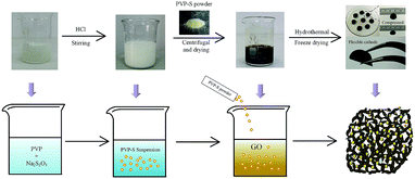 | ||
| Fig. 1 Schematic illustration and corresponding digital images of the synthesis process of the PVP–S/GA composite. | ||
2 Experimental section
2.1 Preparation of the PVP–S composite
In a typical synthesis, 28 mL of 0.35 M Na2S2O3 aqueous solution was mixed with 160 mL of 0.3 M PVP (molecular weight of 58![[thin space (1/6-em)]](https://www.rsc.org/images/entities/char_2009.gif) 000). Then, 12 mL of 1 M HCl was added drop-wise to the above solution with magnetic stirring for 2 h. After the reaction had proceeded for another 2 h at room temperature, the product was centrifuged at 8000 rpm for 10 min to separate the precipitate. To wash the precipitate, it was dispersed in 0.3 M PVP again. After stirring for 5 min, the solution was centrifuged at 7000 rpm for another 10 min. The precipitate was then dried at 50 °C for 4 h and grounded into powder to obtain the PVP–S composite.
000). Then, 12 mL of 1 M HCl was added drop-wise to the above solution with magnetic stirring for 2 h. After the reaction had proceeded for another 2 h at room temperature, the product was centrifuged at 8000 rpm for 10 min to separate the precipitate. To wash the precipitate, it was dispersed in 0.3 M PVP again. After stirring for 5 min, the solution was centrifuged at 7000 rpm for another 10 min. The precipitate was then dried at 50 °C for 4 h and grounded into powder to obtain the PVP–S composite.
2.2 Preparation of the PVP–S/GA and S/GA cathodes
The preparation of PVP–S/GA was based on a two-step hydrothermal reduction and freeze casting method of GO, which was synthesized by an improved Hummers’ method. Typically, 30 mg of PVP–S powder and 20 mg of GO were dispersed into 15 mL of deionized water by ultrasonication. Then, 40 mg of ascorbic acid was added to the above dispersion, followed by stirring for 20 min. For each sample, about 2 mL of the dispersion was sealed in a cylindrical glass vial, which was then placed into a boiling water bath for 25 min. The vial was then immersed into a dry ice bath for 1 h. After being thawed at room temperature, the sample was placed into a boiling water bath again for another 5 h. Finally, the hydrogel was washed with deionized water and then lyophilized to obtain PVP–S/GA. To prepare the cathode, the quasi-cylindrical PVP–S/GA was pressed at 1 MPa into a flexible sheet, which was used as the working electrode directly without additional binder and current collector.As a control sample, pure S/GA was synthesized in a similar way. For example, 158 mg of Na2S2O3 and 20 mg of GO were dispersed into 13 mL of deionized water. 2 mL of 1 M HCl was added drop-wise to the solution with magnetic stirring for 10 min. Then, 40 mg of ascorbic acid was added with stirring for another 20 min to obtain a homogeneous dispersion. Finally, each sample of 2 mL was sealed in a cylindrical glass vial and the subsequent processing was the same as that for PVP–S/GA.
2.3 Materials characterization
Scanning electron microscopy (SEM, Hitachi SU8010) was used to characterize the morphology and structure of the PVP–S/GA composite and the prepared cathode sheet. To evaluate the sulfur loading of PVP–S and PVP–S/GA, thermogravimetric analysis (TGA, Mettler-Toledo TG/DSC1) was performed under nitrogen atmosphere with a heating rate of 10 °C min−1 from room temperature to 400 °C. X-ray diffraction (XRD) patterns were obtained using a Rigaku diffractometer with Cu Kα radiation. Raman spectra were measured using a Renishaw spectrometer (RM-1000) with a 532 nm laser.2.4 Electrochemical measurement
The mechanically pressed quasi-circular sheet with a diameter of around 12–13 mm was directly used as the cathode. The prepared cathode sheet shows good flexibility and electrical conductivity. The mass loading of active sulfur was around 2.4–2.8 mg cm−2. The 2032-type coin cells were fabricated in an Ar-filled glovebox with Li metal foil as the counter electrode and Celgard 2400 polyethylene as the separator. The electrolyte consisted of 1.0 M lithium bis-trifluoromethanesulphonylimide (LiTFSI) and 1 wt% LiNO3 in a mixed solvent of 1,3-dioxolane (DOL) and 1,2-dimethoxyethane (DME) (1![[thin space (1/6-em)]](https://www.rsc.org/images/entities/char_2009.gif) :
:![[thin space (1/6-em)]](https://www.rsc.org/images/entities/char_2009.gif) 1 ratio, by volume). For each battery, 4 drops (about 0.2 mL) of electrolyte were added. Galvanostatic charge/discharge tests were carried out on a LAND CT-2001A instrument. The potential window was controlled from 1.6 V to 2.8 V (vs. Li/Li+). The cyclic voltammogram (CV) tests and electrochemical impedance spectroscopy (EIS) measurements were made using a CHI 660D electrochemical workstation. The potential range of the CV test was from 1.5 V to 2.8 V with a scan rate of 0.1 mV s−1. The frequency range of the EIS measurements was 100 kHz to 10 mHz with a voltage amplitude of 5 mV.
1 ratio, by volume). For each battery, 4 drops (about 0.2 mL) of electrolyte were added. Galvanostatic charge/discharge tests were carried out on a LAND CT-2001A instrument. The potential window was controlled from 1.6 V to 2.8 V (vs. Li/Li+). The cyclic voltammogram (CV) tests and electrochemical impedance spectroscopy (EIS) measurements were made using a CHI 660D electrochemical workstation. The potential range of the CV test was from 1.5 V to 2.8 V with a scan rate of 0.1 mV s−1. The frequency range of the EIS measurements was 100 kHz to 10 mHz with a voltage amplitude of 5 mV.
3 Results and discussion
3.1 Materials characterization
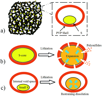
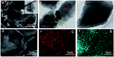
The PVP–S composite was synthesized through a simple reaction between Na2S2O3 and HCl in an aqueous solution in the presence of PVP, and the structure schematic of PVP–S/GA is shown in Fig. 2a. As mentioned above, PVP has served as a template during the reaction of HCl and Na2S2O3 to synthesize PVP-encapsulated sulfur hollow particles with a smaller size. This unique structure has the following advantages: (a) the sulfur particle is encapsulated by the PVP shell, which can restrain the dissolution of the polysulfides. (b) The presence of PVP prevents the aggregation of sulfur particles, ensuring a better dispersibility of PVP–S and a more complete structure of the GA matrix. (c) The polymer shell can make the sulfur more tightly embedded in the GA matrix, and the stable polymer backbone further promotes a better cycling performance. What’s more, it should be noted that the structure of the PVP–S particles is different from the general core–shell structure. For the general core–shell structure, as shown in Fig. 2b, the core is solid. Therefore, although the shell can provide protection for the sulfur core at the beginning of the cycling, the volume expansion of sulfur during lithiation will cause the shell to be broken. Then, the dissolution of the polysulfides will still occur. However, in this work, the PVP–S particles have a unique hollow structure, as shown in Fig. 2c. The hollow particle contains an internal void space which can accommodate the volume change of sulfur. In other words, the sulfur particles will expand inside the hollow area instead of breaking the PVP shell. Therefore, the complete structure of the PVP shell has been retained, offering effective trapping for the polysulfides during the cycling. Meanwhile, the process with PVP–S is environmentally benign because the solution reaction was carried out at room temperature and needed no other complicated treatment. Besides, it should be noted that the concentration of PVP in the aqueous solution has an important effect on the morphology of the generated sulfur particles.4,29 To prepare the PVP–S/GA composite, a two-step hydrothermal reduction and freeze casting method was applied, and the PVP–S particles were dispersed and anchored in the graphene aerogel matrix during this process. Compared with the conventional one-step hydrothermal reduction, this method can regulate the porous structure of GA by changing the time of reduction and condition of pre-freezing.31The SEM image of PVP–S/GA in Fig. 3a clearly shows that the composite exhibits a unique porous and folded structure, which can be attributed to the stacking of the graphene sheets during the hydrothermal reduction and pre-freezing.31 The PVP–S particles were dispersed in the graphene aerogel matrix and wrapped by the graphene sheets, which further ensure the stability of the cathode material during the cycling. The TEM images in Fig. 3b and c reveal that the size of the S particles in the PVP–S is smaller than 1 μm. Meanwhile, the unique hollow structure of PVP–S can also be observed, confirming the effect of PVP in the solution reaction. To further investigate the composition and distribution of the elements, an SEM image of the prepared cathode sheet and the corresponding elemental mappings by EDS are presented in Fig. 3d–f, which indicate the homogeneous distribution of carbon and sulfur.
The content of sulfur in the PVP–S, S/GA and PVP–S/GA composites was measured using a thermogravimetric analyzer under nitrogen atmosphere. As shown in Fig. 4a, sulfur evaporates at around 200–300 °C. The TGA results show that the amounts of sulfur in the S/GA and PVP–S/GA are about 69% and 63%, respectively. Meanwhile, the content of PVP in the PVP–S composite is less than 5%, which has little effect on the sulfur content of the cathode.
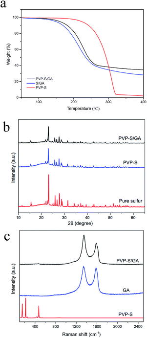 | ||
| Fig. 4 (a) TGA curves of PVP–S, S/GA and PVP–S/GA. (b) XRD patterns of PVP–S/GA, PVP–S and pure sulfur. (c) Raman spectra of PVP–S/GA, GA and PVP–S. | ||
The XRD patterns of PVP–S/GA, PVP–S and pure sulfur are shown in Fig. 4b. The diffraction peaks for crystallized sulfur can still be observed in PVP–S and PVP–S/GA. However, the intensity was obviously weaker than that for pure sulfur, which reveals that the sulfur was successfully encapsulated by PVP and dispersed in the graphene aerogel matrix.14 Fig. 4c shows the Raman spectra of PVP–S/GA, GA and PVP–S. It can be observed that the PVP–S composite exhibits similar characteristic peaks to those of the standard Raman spectra of sulfur, which is consistent with the XRD analysis. On the contrary, PVP–S/GA shows similar characteristic peaks to pure GA, and no obvious characteristic peaks of sulfur can be observed, indicating that the PVP–S particles were well anchored in the graphene aerogel matrix.16
3.2 Electrochemical characterization
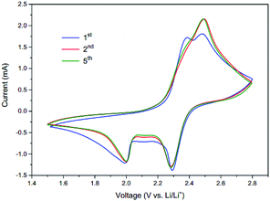
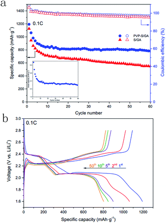
To investigate the electrochemical performance, the PVP–S/GA composites were pressed into flexible sheets at 1 MPa and directly used as a cathode without any other additives. Fig. 5 shows the cycle voltammograms of the PVP–S/GA cathode. During the cathodic scan, there are two typical reduction peaks at around 2.3 V and 2.0 V, corresponding to the two-step reduction of elemental sulfur. The peak at 2.3 V indicates the reduction of elemental sulfur to soluble long-chain lithium polysulfides (Li2Sx, 4 < x < 8), and the peak at 2.0 V is assigned to the subsequent formation of insoluble short-chain Li2S2/Li2S. In the following anodic scan, only one peak can be found at around 2.5 V, corresponding to the oxidation of Li2S2/Li2S.2 Meanwhile, after the stabilization of the first cycle, the peak currents and potentials show no obvious change during subsequent cycles, demonstrating the electrochemical stability of the PVP–S/GA cathode. Besides, there is a high anodic base line current at 2.8 V, which is likely caused by some degree of shuttling reaction.25Fig. 6a shows the cycling performances of the PVP–S/GA and S/GA cathodes at 0.1C. The PVP–S/GA delivers an initial discharge specific capacity of 1192.6 mA h g−1 with a high areal sulfur loading of around 2.8 mg cm−2. The corresponding areal capacity of PVP–S/GA is shown in the inset of Fig. 6a, which reaches a highest areal capacity of 3.34 mA h cm−2. Fig. 6b shows the corresponding discharge/charge curves of the PVP–S/GA cathode for different cycle numbers. Two apparent plateaus during the discharge process and one plateau during the charge process can be observed, representing the reducing and oxidizing reaction of the cathode, respectively. Meanwhile, it should be noted that after the first few cycles and stabilization, the PVP–S/GA cathode exhibits a great cycling stability. The capacity retention reaches 94.6% from the 10th to 50th cycle with a reversible capacity of 803.3 mA h g−1 and a coulombic efficiency of more than 95%. For comparison, the pure S/GA sample shows a relatively poorer performance with a capacity retention of 81.2% from the 10th to 50th cycle (only 580.1 mA h g−1 after 50 cycles at 0.1C), even though it performs with a similar initial specific capacity of 1124.9 mA h g−1. The relatively high initial specific capacity can be attributed to the excellent electrical conductivity and porous structure of the graphene aerogel matrix, which greatly improve the conductivity of the composite cathode and offer more active sites for the electrode reaction, increasing the utilization of sulfur. However, a simple physical confinement and absorption process is not sufficient to suppress the dissolution of the lithium polysulfides, especially after long-term cycles.25 The dissolved lithium polysulfides result in irreversible loss of active material and the shuttle effect, further causing a lower reversible capacity after long-term cycles.
To further explore the effects of PVP encapsulation, the long-term cycling performances of the PVP–S/GA and S/GA cathodes at 0.5C were tested, as shown in Fig. 7a. The PVP–S/GA cathode delivers a high initial specific capacity of 1013.1 mA h g−1 at 0.5C. More importantly, after the stabilization of the first few cycles, the capacity retention reaches 75.3% from the 20th to 200th cycle. The cathode retains a reversible discharge capacity of 508.2 mA h g−1 after 200 cycles with an average coulombic efficiency of more than 95%, demonstrating a great cycling stability and high reversibility. On the contrary, the pure S/GA cathode performs with a lower initial specific capacity of 921.9 mA h g−1. Moreover, after 200 cycles, the reversible capacity decreases to only 264.5 mA h g−1, corresponding to a capacity retention of only 45.9% from the 20th to 200th cycle with a relatively lower coulombic efficiency than that of PVP–S/GA. The enhanced cycling stability of PVP–S/GA can be attributed to the encapsulation of sulfur with PVP. Compared with pure S/GA, the presence of PVP during the solution reaction can make the sulfur disperse in the graphene aerogel matrix more homogeneously and enable uniform PVP–S particles to be obtained,26,29 increasing the utilization of the active material at a high current rate. Meanwhile, the PVP-encapsulated sulfur can be better anchored in the graphene aerogel matrix, which incorporates the chemisorption of the polymers into the physical confinement of the porous structure, inhibiting the dissolution of the lithium polysulfides and further improving the cycling stability of the cathode.
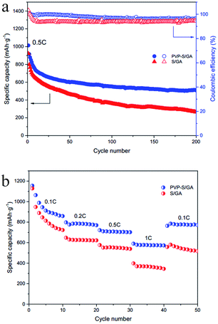 | ||
| Fig. 7 (a) Long-term cycling performances and the coulombic efficiency of PVP–S/GA and S/GA at 0.5C. (b) Rate capability of PVP–S/GA and S/GA at rates from 0.1C to 1C. | ||
Fig. 7b shows the rate capability of the PVP–S/GA and S/GA cathodes at various rates from 0.1C to 1C. Although the two composites deliver a similar initial specific capacity of 1155.9 mA h g−1 and 1128.8 mA h g−1 at 0.1C, respectively, the PVP–S/GA cathode exhibits a higher capacity of 776.8 mA h g−1, 710.8 mA h g−1 and 578.9 mA h g−1 at 0.2C, 0.5C and 1C, respectively. On the other hand, the pure S/GA cathode delivers a capacity of only 630.3 mA h g−1, 551.4 mA h g−1 and 369.3 mA h g−1 under the same respective conditions. More importantly, when the discharge/charge rate is restored to 0.1C again, the capacity of the PVP–S/GA cathode recovers to 784.9 mA h g−1, much more than that of the pure S/GA cathode, indicating a good rate capacity at different current densities. This improved performance can be ascribed to the unique electrode structure and multiple effects of PVP–S/GA. Compared with pure S/GA and pristine carbon materials, PVP serves as a more superior protective layer to constrain sulfur, effectively suppressing the dissolution of the lithium polysulfides and the loss of the active material. On the other hand, although both sulfur and PVP are electrically insulating, the graphene aerogel matrix greatly improves the conductivity of the composite cathode, which is beneficial for the transmission of ions and electrons, improving the performances under a high current rate.
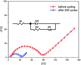
Electrochemical impedance spectra of the PVP–S/GA cathode before and after cycling were taken to further investigate its performances, as shown in Fig. 8. A simple semicircle in the high frequency region can be observed, which is ascribed to the charge transfer resistance, Rct, as illustrated in the equivalent circuit model. It can be seen that the PVP–S/GA cathode exhibits a very low charge transfer resistance of only 88.7 Ω before cycling, revealing a good contact between PVP–S and the graphene aerogel matrix due to the unique electrode structure, which lowers the resistance for electrons transferring. Meanwhile, after 200 cycles, the value of the charge transfer resistance further decreases to 34.7 Ω, which can be attributed to the good electrolyte infiltration into the cathode14 and much easier charge transport. Table 1 further shows a comparison of the PVP–S/GA cathode in this work with reported results at 0.1C. It should be noted that the sulfur content was calculated by the entire electrode mass, including the conductive additive and binder (for the binder-free electrode, this value is equal to the sulfur content in the composite). Although the gravimetric capacity is lower compared to those in some literature, when taking the high areal sulfur loading into account, the cathodes in this work exhibit a high areal capacity and great holistic performance. In summary, these results confirm that the presence of the graphene aerogel matrix and the unique electrode structure can greatly improve the conductivity of the composite cathode, which allows faster ion and electron transport, and leads to a higher utilization of the sulfur. Besides, the combined effects of PVP and graphene aerogel better suppress the dissolution of the lithium polysulfides and the loss of the active material, effectively enhancing the cycling stability of the Li–S batteries.
| Cathode materials | Gravimetric capacity (mA h g−1) | Sulfur content (%) | Areal sulfur loading (mg cm−2) | Areal capacity (mA h cm−2) |
|---|---|---|---|---|
| Sulfur/graphene/carbon nanotube composite10 | 1468 | 57 | 1.0 | 1.47 |
| Sandwich-type graphene@microporous carbon13 | 1320 | 60 | 1.5 | 1.98 |
| Flexible nanostructured paper15 | 1234 | 56 | 2.2 | 2.71 |
| 3D graphene framework sulfur composite21 | 1077 | 90 | 4.3 | 4.65 |
| Sulfur/carbonized bacterial cellulose composite23 | 1134 | 75 | 1.1–1.5 | 1.70 |
| PVP–S/GA (this study) | 1192 | 63 | 2.4–2.8 | 3.34 |
4 Conclusions
In summary, we synthesized a novel three-dimensional PVP–S/GA composite through a facile no-slurry method, which was then pressed into flexible sheets and directly used as a cathode without any additives. Due to its unique microstructure, this composite has an excellent electrical conductivity and enables a high areal sulfur loading. The as prepared PVP–S/GA cathode delivers a high initial gravimetric specific capacity of 1192.6 mA h g−1 and an areal specific capacity of 3.34 mA h cm−2 at 0.1C. Meanwhile, compared with pure S/GA, PVP–S/GA exhibits an enhanced cycling stability and rate capability. The capacity retention reaches 94.6% from the 10th to 50th cycle at 0.1C and 75.3% from the 20th to 200th cycle at 0.5C. The improved performances can be attributed to the combination of PVP and the graphene aerogel matrix, which incorporates the chemisorption of the polymer into the physical confinement of the porous structure, effectively restraining the dissolution of the lithium polysulfides. Moreover, this no-slurry method based on graphene aerogel provides a new way to prepare composite cathodes, which is promising and can be integrated with other composites and further improve the performances of Li–S batteries.Conflicts of interest
There are no conflicts to declare.Acknowledgements
This research was supported by the Fundamental Research Funds for the Central Universities (HUST: No. 2016YXMS205) and the Creative Technology Project of Hubei Province: No. 2016AAA048.References
- A. Rosenman, E. Markevich, G. Salitra, D. Aurbach, A. Garsuch and F. F. Chesneau, Adv. Energy Mater., 2015, 5, 1500212 CrossRef.
- M. Wild, L. O’Neill, T. Zhang, R. Purkayastha, G. Minton, M. Marinescu and G. Offer, Energy Environ. Sci., 2015, 8, 3477–3494 CAS.
- G. Zhou, S. Pei, L. Li, D.-W. Wang, S. Wang, K. Huang, L.-C. Yin, F. Li and H.-M. Cheng, Adv. Mater., 2014, 26, 625–631 CrossRef CAS PubMed.
- Z. W. Seh, W. Li, J. J. Cha, G. Zheng, Y. Yang, M. T. McDowell, P.-C. Hsu and Y. Cui, Nat. Commun., 2013, 4, 1331 CrossRef PubMed.
- L.-L. Kong, Z. Zhang, Y.-Z. Zhang, S. Liu, G.-R. Li and X.-P. Gao, ACS Appl. Mater. Interfaces, 2016, 8, 31684–31694 CAS.
- C. Yan, X.-B. Cheng, C.-Z. Zhao, J.-Q. Huang, S.-T. Yang and Q. Zhang, J. Power Sources, 2016, 327, 212–220 CrossRef CAS.
- Y. Zhang, Y. Zhao, D. Gosselink and P. Chen, Ionics, 2015, 21, 381–385 CrossRef CAS.
- M. D. Walle, Z. Zhang, X. You, M. Zhang, J. M. Chabu, Y. Li and Y.-N. Liu, RSC Adv., 2016, 6, 78994–78998 RSC.
- Y.-L. Ding, P. Kopold, K. Hahn, P. A. van Aken, J. Maier and Y. Yu, Adv. Funct. Mater., 2016, 26, 1112–1119 CrossRef CAS.
- G. Yuan, G. Wang, H. Wang and J. Bai, J. Nanoparticle Res., 2015, 17, 36 CrossRef.
- J. Guo, Y. Xu and C. Wang, Nano Lett., 2011, 11, 4288–4294 CrossRef CAS PubMed.
- N. Jayaprakash, J. Shen, S. S. Moganty, A. Corona and L. A. Archer, Angew. Chem., 2011, 123, 6026–6030 CrossRef.
- N.-W. Li, Y.-X. Yin and Y.-G. Guo, RSC Adv., 2016, 6, 617–622 RSC.
- R. Fang, S. Zhao, S. Pei, X. Qian, P.-X. Hou, H.-M. Cheng, C. Liu and F. Li, ACS Nano, 2016, 10, 8676–8682 CrossRef CAS PubMed.
- J. Cao, C. Chen, Q. Zhao, N. Zhang, Q. Lu, X. Wang, Z. Niu and J. Chen, Adv. Mater., 2016, 28, 9629–9636 CrossRef CAS PubMed.
- J. Feng, X. Qin, Z. Ma, J. Yang, W. Yang and G. Shao, Electrochim. Acta, 2016, 190, 426–433 CrossRef CAS.
- K. Balakumar and N. Kalaiselvi, RSC Adv., 2015, 5, 34008–34018 RSC.
- Y. Xie, Z. Meng, T. Cai and W.-Q. Han, ACS Appl. Mater. Interfaces, 2015, 7, 25202–25210 CAS.
- Z. Zhang, Z. Li, F. Hao, X. Wang, Q. Li, Y. Qi, R. Fan and L. Yin, Adv. Funct. Mater., 2014, 24, 2500–2509 CrossRef CAS.
- M. Yu, A. Wang, F. Tian, H. Song, Y. Wang, C. Li, J.-D. Hong and G. Shi, Nanoscale, 2015, 7, 5292–5298 RSC.
- B. Papandrea, X. Xu, Y. Xu, C.-Y. Chen, Z. Lin, G. Wang, Y. Luo, M. Liu, Y. Huang and L. Mai, et al., Nano Res., 2016, 9, 240–248 CrossRef.
- J.-Q. Huang, T.-Z. Zhuang, Q. Zhang, H.-J. Peng, C.-M. Chen and F. Wei, ACS Nano, 2015, 9, 3002–3011 CrossRef CAS PubMed.
- Y. Huang, M. Zheng, Z. Lin, B. Zhao, S. Zhang, J. Yang, C. Zhu, H. Zhang, D. Sun and Y. Shi, J. Mater. Chem. A, 2015, 3, 10910–10918 CAS.
- J.-Q. Huang, Z.-L. Xu, S. Abouali, M. A. Garakani and J.-K. Kim, Carbon, 2016, 99, 624–632 CrossRef CAS.
- L. Xiao, Y. Cao, J. Xiao, B. Schwenzer, M. H. Engelhard, L. V. Saraf, Z. Nie, G. J. Exarhos and J. Liu, Adv. Mater., 2012, 24, 1176–1181 CrossRef CAS PubMed.
- W. Li, Q. Zhang, G. Zheng, Z. W. Seh, H. Yao and Y. Cui, Nano Lett., 2013, 13, 5534–5540 CrossRef CAS PubMed.
- Y. Qiu, W. Li, G. Li, Y. Hou, L. Zhou, H. Li, M. Liu, F. Ye, X. Yang and Y. Zhang, Nano Res., 2014, 7, 1355–1363 CrossRef CAS.
- X. Tan, P. Lv, K. Yu, Y. Ni, Y. Tao, W. Zhang and W. Wei, RSC Adv., 2016, 6, 45562–45568 RSC.
- W. Li, G. Zheng, Y. Yang, Z. W. Seh, N. Liu and Y. Cui, Proc. Natl. Acad. Sci. U. S. A., 2013, 110, 7148–7153 CrossRef CAS PubMed.
- Y. Dong, S. Liu, Z. Wang, Y. Liu, Z. Zhao and J. Qiu, Nanoscale, 2015, 7, 7569–7573 RSC.
- L. Qiu, J. Z. Liu, S. L. Chang, Y. Wu and D. Li, Nat. Commun., 2012, 3, 1241 CrossRef PubMed.
| This journal is © The Royal Society of Chemistry 2017 |

