 Open Access Article
A facile in situ approach to ion gel based polymer electrolytes for flexible lithium batteries†
Bingyu Huang‡
a,
Youdi Zhang‡a,
Mingming Quea,
Yingbo Xiaoa,
Yaoquan Jiangc,
Kai Yuan *ab and
Yiwang Chen
 ab
ab
aCollege of Chemistry, Nanchang University, 999 Xuefu Avenue, Nanchang 330031, China. E-mail: kai.yuan@ncu.edu.cn; Fax: +86 791 83969561; Tel: +86 791 83968703
bJiangxi Provincial Key Laboratory of New Energy Chemistry/Institute of Polymers, Nanchang University, 999 Xuefu Avenue, Nanchang 330031, China
cJiangxi Ganfeng Lithium Co., Ltd, 608 Nanyuan Road, Xinyu 338015, China
First published on 28th November 2017
Abstract
Inherent safety and stability issues arising from the use of traditional organic liquid electrolytes in lithium-based batteries are currently limiting their application to flexible electronics and large-scale energy storage from renewable sources. Gel polymer electrolytes (GPE) with chemical cross-linked structures and green ionic liquids as plasticizers represent a solution to this problem. In this study, a novel type of GPE with an interpenetrating polymer network (IPN-GPE) is prepared by a simple in situ thermally induced free radical polymerization. The as-prepared IPN-GPE with cross-linked structure displays a combination of high flexibility and deformability as well as thermal stability (over 310 °C). Moreover, IPN-GPE possesses a superior electrochemical stability window (5 V vs. Li+/Li) as well as a considerable ionic conductivity of 1.3 × 10⁻³ S cm−1 at 30 °C. Therefore, with such an IPN-GPE gel electrolyte membrane, Li/IPN-GPE/LiFePO4 devices deliver superior stable charge/discharge profiles and remarkable cycling performance and rate capability. This simple, effective and low-cost in situ synthesis strategy makes IPN-GPE one of the most promising polymer electrolyte candidates for next generation rechargeable lithium-based batteries with highly elevated electrochemical performance and safety.
1. Introduction
Portable energy storage devices afford many advantages, for example, they can be embedded in textiles/clothing or attached to biological organs.1,2 Among the various energy storage devices, rechargeable lithium-ion batteries (LIBs) have gained extensive attention and successful application in consumable electronic devices attributed to their superior properties including high energy density and efficiency.3–6 Over the past decades, several kinds of structural and material designs for the fabrication of flexible LIBs have been proposed.7–14 Keun-Ho Choi et al. developed a thin and deformable plastic crystal based all solid state polymer electrolytes, that can work in the bent state.15 Zhang et al. designed a rigid-flexible coupling cellulose supporting poly(propylene carbonate) based polymer electrolyte (CPPC-SPE) exhibiting excellent electrochemical performance and superior rate capability.16 Lukman fabricated bendable LIBs which employed paper-like free-standing V2O5–polypyrrole as cathodes prepared by vacuum filtration.17Electrolytes play a crucial role in designing flexible LIBs. The traditional carbonate nonaqueous liquid electrolytes (e.g., propylene carbonate (PC), ethylene carbonate (EC), dimethyl carbonate (DMC), and diethyl carbonate (DEC), etc.) used in most of pouch-type batteries are encountering safety issues (fire or explosion hazards) due to their poor mechanical stability and risk of leakage, especially when closely packed into a large format module. Polymer electrolytes are considered as one of the effective solutions.18–20 Solid polymer electrolytes show superior stability and safety, but their low ionic conductivity (σ ≈ 10−6 to 10−5 S cm−1) at ambient results in insufficient electrochemical performance, which limits their further application in large scale electronics.21,22 In order to develop relatively safer electrolyte toward high-performance LIBs, much efforts have been paid on gel polymer electrolytes (GPE). Ionic liquids are commonly used to replace the traditional organic liquid electrolytes for preparing GPE with high safety due to their several advantageous properties including liquid phase at room temperature (low-melting temperature salts), high ionic conductivity, non-flammability, non-volatility as well as thermal and chemical stability.23–25 However, gel type polymer electrolytes often suffer from an inferior mechanical performance attribute to the liquid state immobilized in the polymer matrix, some of which are sticky or hard to be handle when the liquid state is include.26–28 Moreover, GPEs are mostly produced by ex situ solution casting with a large amount of organic solvents as well as tedious fabrication procedures, thus resulting in increased cost.29
Herein, to address above-mentioned issues, a novel type of GPE with interpenetrating polymer networks (IPN-GPE) is prepared by a facile in situ thermal induced free radical polymerization of (1-[(2-methacryloyloxy) hexyl]-3-butylimidazolium bis(trifluoromethanesulphonyl) imide) (MHBIm-TFSI), poly(ethylene glycol) diacrylate (PEGDA) and 1-ethyl-3-methylimidazolium bis(trifluoromethylsulfonyl)imide (EMIM-TFSI) with the presence of porous and nanofibrous poly(vinylidene fluoride-co-hexafluoropropylene) (PVDF-HFP) film serves as frame matrix. The PVDF-HFP electrospun membrane with large surface-to-volume ratio and a plenty of pores is beneficial for the infiltration of ion gel-based electrolyte during the in situ polymerization, resulting in the PVDF-HFP fibers embedded in the polymeric network endows the membrane flexibility. The in situ generated IPN-GPE exhibits an excellent interfacial compatibility with electrodes as well as superior electrochemical stability window (5 V vs. Li+/Li) and impressive ionic conductivity up to 1.3 × 10⁻³ S cm−1 at 30 °C. Thereby, Li/LIFePO4 batteries based on IPN-GPE deliver stable charge/discharge profiles, remarkable rate capability and cycling performance. This environmentally-friendly and simply procedure to IPN-GPE provides a promising strategy for next generation rechargeable lithium-based batteries with highly improved electrochemical performance and safety.
2. Experimental section
2.1 Materials
Methacryloyl chloride (97%), triethylamine (>99%), anhydrous magnesium sulfate, 1-butylimidazole (98%), 6-bromo-1-hexanol (97%), 2,2′-azobis(2-methylpropionitrile) (AIBN), poly(ethylene glycol) methyl ether methacrylate (PEGMA Mn = 900) were purchased from Energy Chemical. Poly(vinylidene fluoride-co-hexafluoropropylene) (PVDF-HFP), (Mn = 4 × 10⁵ g mol−1, Aldrich), lithium bis(trifluoromethane sulfonyl)imide (LiTFSI, 98%), 1-ethyl-3-methylimidazolium bis(trifluoromethanesulfonyl)imide (EMIM-TFSI, 98%), LiFePO4, lithium metal anode, carbon black, and PVDF binder were purchased from Damao Chemicals, Tianjin, China. Dichloromethane, acetone, acetonitrile, diethyl ether, methyl alcohol, toluene, tetrahydrofuran (THF), dimethylformamid (DMF) and N,N-dimethylformamide (NMP) were purchased from Shanghai Reagent Co., Ltd.2.2 Preparation of interpenetrating network like gel polymer electrolyte (IPN-GPE)
The synthesis rout of 1-[(2-methacryloyloxy) hexyl]-3-butylimidazolium bis(trifluoromethanesulphonyl) imide (MHBIm-TFSI) is shown in Scheme S1,† and detailed synthesis procedures are given in the ESI.† For fabricate interpenetrating network like gel polymer electrolyte (IPN-GPE), reactive precursor solutions were first prepared by mixing of MHBIm-TFSI, PEGDA, EMIM-TFSI, 0.5 M LiTFSI along with 1 wt% AIBN as initiator. In the precursor solution, the weight ratio of MHBIm-TFSI to PEGDA is 5![[thin space (1/6-em)]](https://www.rsc.org/images/entities/char_2009.gif) :
:![[thin space (1/6-em)]](https://www.rsc.org/images/entities/char_2009.gif) 1. The mole ratio of MHBIm-TFSI to EMIM-TFSI in the precursor solution is varies from 10/0 to 8/2, 5/5 and 3/7. The mixture is vigorously stirred until form a homogeneous precursor solution. Then porous PVDF-HFP membranes are immersed into the precursor solution for 2 h. Later, the precursor membrane is kept at 70 °C for 12 h in an oven under argon flux to complete the thermal polymerization. The obtained gel polymer electrolytes are named IPN-GPE 10, IPN-GPE 8/2, IPN-GPE 5/5, and IPN-GPE 3/7, respectively. The individual components in IPN-GPE 10, IPN-GPE 8/2, IPN-GPE 5/5, and IPN-GPE 3/7 are summarized in Table S1.† The proposed in situ synthesis allowed direct incorporation of EMIM-TFSI in the polymer electrolyte with the formation of the cross-linked networks.
1. The mole ratio of MHBIm-TFSI to EMIM-TFSI in the precursor solution is varies from 10/0 to 8/2, 5/5 and 3/7. The mixture is vigorously stirred until form a homogeneous precursor solution. Then porous PVDF-HFP membranes are immersed into the precursor solution for 2 h. Later, the precursor membrane is kept at 70 °C for 12 h in an oven under argon flux to complete the thermal polymerization. The obtained gel polymer electrolytes are named IPN-GPE 10, IPN-GPE 8/2, IPN-GPE 5/5, and IPN-GPE 3/7, respectively. The individual components in IPN-GPE 10, IPN-GPE 8/2, IPN-GPE 5/5, and IPN-GPE 3/7 are summarized in Table S1.† The proposed in situ synthesis allowed direct incorporation of EMIM-TFSI in the polymer electrolyte with the formation of the cross-linked networks.
2.3 Cell assembly
For electrochemical testing in lithium cells, precursor membrane with mixed solution immersed in the porous PVDF-HFP microfibers cover on the surface of LiFePO4 electrode surface. Then precursor solution successively under went thermal polymerization in this form (Scheme 1). Li/LiFePO4 cells were fabricated in the argon-filled glove box with IPN-GPE 3/7 as electrolyte. Both 2025-type coin cell and pouch cell were fabricated. LiFePO4 electrodes were prepared by mixing the LiFePO4 powder, PVDF and carbon black in the weight ratio of 80![[thin space (1/6-em)]](https://www.rsc.org/images/entities/char_2009.gif) :
:![[thin space (1/6-em)]](https://www.rsc.org/images/entities/char_2009.gif) 10
10![[thin space (1/6-em)]](https://www.rsc.org/images/entities/char_2009.gif) :
:![[thin space (1/6-em)]](https://www.rsc.org/images/entities/char_2009.gif) 10 with the presence of N-methylpyrrolidone (NMP). Then, the mixture was coated onto aluminum foil and dried at 80 °C for 12 h. Finally, the cells were assembled in an argon-filled glove box with a moisture level <10 ppm.
10 with the presence of N-methylpyrrolidone (NMP). Then, the mixture was coated onto aluminum foil and dried at 80 °C for 12 h. Finally, the cells were assembled in an argon-filled glove box with a moisture level <10 ppm.
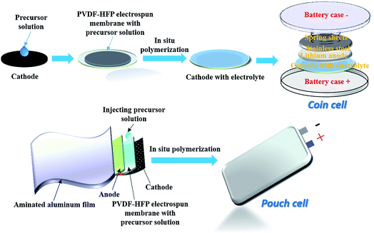 | ||
| Scheme 1 Schematic illustration of in situ preparation of IPN-GPE electrolyte and the cell assembly procedure. | ||
2.4 Characterizations
The structures of the synthesized ionic liquid monomer and polymer ionic liquid were characterized by nuclear magnetic resonance (1H NMR, Bruker ARX 400 NMR) with tetramethylsilane (TMS, δ = 0) and DMSO-d6 as internal standard and solvent, respectively. Infrared (IR) spectroscopy was recorded on a Shimadzu IR Prestige-21 Fourier transform infrared (FT-IR) spectrum-photometer. Thermal gravimetric analysis (TGA) experiments were conducted from 0 to 600 °C by TA instruments (Q20 analyzer) under N2 at a heating rate of 10 °C min−1. Phase-transition temperatures were determined by differential scanning calorimetry (DSC) on TA DSC Q2000 under a continuous nitrogen purge (50 mL min−1) with a heating/cooling rate of 10 °C min−1. Zahner Zennium electrochemical analyzer (IM6ex, Germany) was used to measure the ionic conductivity of the as-prepared electrolyte by sandwiching electrolyte between two stainless-steel blocking electrodes (surface area of 2 cm2) at different temperatures. The measurements were performed from 30 to 100 °C, and the data was collected with the amplitude of 10 mV at an open circuit potential over a frequency range of 1–105 Hz. The ionic conductivity σ of the electrolyte was determined by the bulk electrolyte resistance (R) through the following equation:where Rb is the bulk resistance of the GPE film, L and S the thickness and area of the GPE film, respectively. Linear sweep voltammetry (LSV) was used to measure the electrochemical stability window of GPE from open circuit potential to 7 V (for the anodic sweeps) and −0.3 V (for the cathodic sweeps) at a scan rate of 5 mV S−1. Stainless steel was served as the working electrode and lithium metal as both counter and reference electrode. Li/IPN-GPE 3/7/LiFePO4 cells were used to evaluate the cycling performance of the electrolyte by an Neware BTS (Shenzhen, China) automatic galvanostatic charge–discharge unit over the range of 2.5–4 V.
3. Results and discussion
3.1 Chemical structure and thermal properties of IPN-GPE
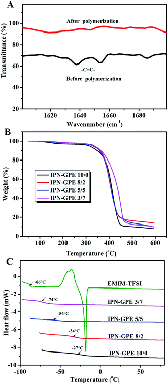
Firstly, the heat-curing reaction of MHBIm-TFSI and PEGDA to generate IPN-GPE was elucidated by FTIR spectroscopy. As shown in Fig. 1A, the peaks around 1610–1625 cm−1 are assigned to the –C![[double bond, length as m-dash]](https://www.rsc.org/images/entities/char_e001.gif) C– stretching of MHBIm-TFSI and PEGDA monomers. After polymerization, the characteristic peaks of the –HC
C– stretching of MHBIm-TFSI and PEGDA monomers. After polymerization, the characteristic peaks of the –HC![[double bond, length as m-dash]](https://www.rsc.org/images/entities/char_e001.gif) CH– bonds were disappeared, indicating that the cross-linking reactions of the MHBIm-TFSI and PEGDA monomers were successfully conducted to form a crosslinked polymer framework to generate the IPN-GPE in the presence of AIBN.30,31
CH– bonds were disappeared, indicating that the cross-linking reactions of the MHBIm-TFSI and PEGDA monomers were successfully conducted to form a crosslinked polymer framework to generate the IPN-GPE in the presence of AIBN.30,31
The thermal characteristics of the IPN-GPE were characterized by TGA and DSC under N2 atmosphere. As show in Fig. 1B, all samples undergo single weight loss processes. A high temperature (310 °C) one-step weight loss is observed, which assigned to the heat resistance of the crosslinked polymer framework of IPN-GPE, suggesting IPN-GPE are highly stable and safe even at high temperature.32 Such remarkable thermal stability of the IPN-GPE is of key importance for improving the safety of LIBs.
The glass transition temperature (Tg) of EMIM-TFSI, IPN-GPE 10, IPN-GPE 8/2, IPN-GPE 5/5, and IPN-GPE 3/7 polymer electrolytes were evaluated by DSC analysis, and the corresponding thermograms are shown in Fig. 1C. EMIM-TFSI displays a sharp endothermic peak and a heat capacity change corresponding to the melting point (Tm, −16 °C) and Tg (−86 °C), respectively. The coexistence of the Tm and Tg implies relatively slow crystallization kinetics of EMIM-TFSI.33 The analyses evidenced a decrease in Tg values with increasing of the content of EMIM-TFSI. The Tg value is decreased from −27 °C (for IPN-GPE 10) to −74 °C (for IPN-GPE 3/7). It is consistent with the plasticized effect of EMIM-TFSI to the polymer host. This result portends the possession of fine chain mobility and low activation energy for ion transport in the IPN-GPE 3/7 electrolyte. We also compared the Tg data with literature results, as listed in Table S2.† IPN-GPE 3/7 shows comparable or even better performance with other reported gel polymer electrolytes.
3.2 Morphology of IPN-GPE
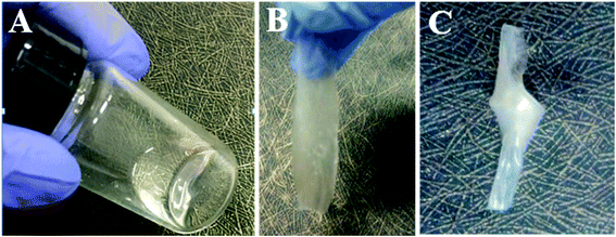
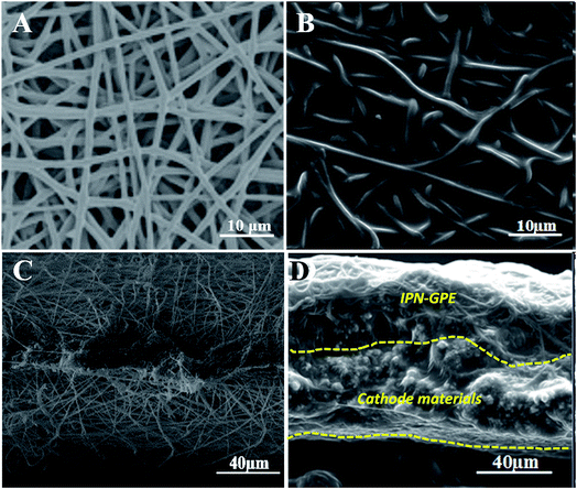
As illustrated in Scheme 1, IPN-GPE is fabricated by filling the precursor solution into the porous electrospun membranes followed by in situ polymerization. The precursor solution is fluid and transparent liquid (as shown in Fig. 2A), which make the injecting and the following heat-curing procedure possible. After curing in the PVDF-HFP electrospun substrate, the composite became translucent (Fig. 2B). The as prepared IPN-GPE is flexible and foldable. When knotted, no crack is found in the surface of IPN-GPE, as presented in Fig. 2C. Moreover, as the incorporation of PVDF-HFP skeleton, the maximum tensile strength of IPN-GPE 3/7 membrane can reach 7.3 MPa (Fig. S1†) with an elongation at break of 82%. The high flexibility property of the IPN-GPE membrane is beneficial for achieving close contact between it and the electrodes in the fabrication of LIBs.Scanning electron microscope (SEM) was employed to observe the surface morphology and cross-section of IPN-GPE. As show in Fig. 3A, the PVDF-HFP electrospun film is composed of uniform nanofibers with smooth surface and homogenous diameter. The nanofibres are overlapped and interlaced randomly with each other, forming an interconnected porous structure with plenty of pores and interspaces. Such continuous electrospun fibers are good candidates to work as robust skeleton for loading plentiful ion gel with desirable mechanical strength. As depicted in Fig. 3B, after the curing procedure, the pores and interspaces are fully infiltrated with ion gel. No interconnect pores and interspaces were observed in both surface and cross-section of the composite membrane compared with those of PVDF-HFP electrospun membrane (Fig. 3C and D), demonstrating a complete infiltration of gel electrolyte into the porous PVDF-HFP substrate. To investigate the microstructure and interfacial property between IPN-GPE and electrodes, SEM image of cross-section of LiFePO4 electrode with IPN-GPE was performed. From Fig. 3D, a closed adhesion between LiFePO4 electrode and IPN-GPE can be observed. Some polymer electrolyte was even incorporated into the pores of the porous cathodes originated from the in situ polymerization of mixed solution. These findings manifested the closed contact between the IPN-GPE and cathode interface, which would be greatly beneficial for reduce impedance and improve charge/discharge.
3.3 Electrochemical properties and combustion performance of IPN-GPE
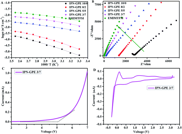
Impedance spectroscopy is used to investigate the ionic conductivity of IPN-GPE at different temperatures (from 30 °C to 100 °C) by using an AC impedance analyzer with the IPN-GPE samples sandwiched between two stainless steel blocking electrodes. The temperature dependence of ionic conductivity is shown in Fig. 4A. Ionic conductivity of IPN-GPE system enhanced with the increase of EMIM-TFSI content, which owes to the plasticized effect of imidazolium ionic liquids. IPN-GPE 3/7 can reach considerable ionic conductivity of 1.3 × 10⁻³ S cm−1 at 30 °C. When the mole ratio of monomer to ionic liquid is above 3/7, the physical state of IPN-GPE become sticky and can hardly to form solid like state. Therefore, IPN-GPE 3/7 is selected for the cell assembling. For all IPN-GPE samples, the ionic conductivity is temperature dependent, i.e., the ionic conductivity enhances when increase the temperature. This is attributed to higher temperature improves the movement of polymer segments and the motion of lithium ions. The temperature dependent ionic conductivity of polymer electrolytes is found to obey the Vogel-Tammann-Fulcher (VTF) empirical equation:σ = σ0![[thin space (1/6-em)]](https://www.rsc.org/images/entities/char_2009.gif) exp[−B/(T − T0)] exp[−B/(T − T0)] |
The characteristic electrochemical impedance (EIS) plots of IPN-GPE with different EMIM-TFSI contents at temperatures arranged from 30 °C to 100 °C are presented in Fig. 4B. Unlike the case of common solid polymer electrolytes based on polyethylene oxide, the Nyquist plot for the IPN-GPE fabricated with ionic liquid do not show a semi-circle in the high frequency region. This ascribed to the low Tg of IPN-GPE, which ensure segment's remarkable mobility and short relaxation time of the high-frequency response.
The electrochemical stability of polymer electrolytes is very important for practical battery applications. We further evaluated the electrochemical stability of IPN-GPE within the operation voltage of the battery system. As depicted in Fig. 4C, the breakdown voltage of IPN-GPE 3/7 occurring around 5 V (vs. Li+/Li). As shown in cyclic voltammetry curve (Fig. 4D), the cathodic current at about −0.2 V for IPN-GPE 3/7 may correspond to the lithium plating. Additionally, cathodic current that is smaller than the current threshold around 0.5–1.5 V (vs. Li/Li+). This most likely associates to the reduction of slight impurities (such as H2O) and the imidazolium ring of EMIM-TFSI in the composite electrolyte.36 This may affect overall performance of lithium ion battery with graphite anode materials. Thus, anode material with high potential for Li-intercalation (≥1.5 V vs. Li/Li+), such as Li4Ti5O12 anode, may be feasible when IPN-GPE 3/7 is applied as electrolyte.
Generally, when exposed to hash conditions such as short circuit, high temperature and overcharging, the traditional carbonate electrolytes show a high tendency to trigger fire or explosions.37 For safety comparison, combustion tests of conventional carbonate-based (1 M LiPF6 in EC/DMC/DEC = 1/1/1, v/v) liquid electrolyte and IPN-GPE 3/7 are presented in Fig. S2.† Compared with the highly combustible carbonate liquid electrolyte, the IPN-GPE 3/7 does not exhibits combustion behavior and is hardly ignited by the flame. This extremely low flammability of IPN-GPE 3/7 is attribute to its stable cross-linked structure as well as thermal robustness with a high decomposition temperature of 310 °C (the TGA profile in Fig. 1B), which is beneficial for improving the safety performance of LIBs.
3.4 Charge/discharge performance of Li/LiFePO4 cells
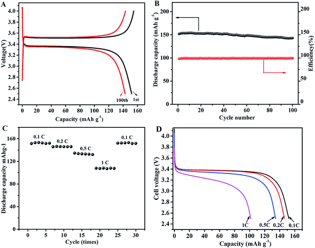
To investigate the electrochemical performance of IPN-GPE 3/7 as electrolyte in lithium batteries, coin-type cells are first fabricated with LiFePO4 as cathode and Li as anode. The initial and the 100th charge–discharge curves for a Li/IPN-GPE 3/7/LiFePO4 at 0.1C are presented in Fig. 5A. The Li/IPN-GPE 3/7/LiFePO4 cell can achieve discharge capacity of about 152 mA h g−1 at a current density of 0.1C at 40 °C. After several cycles, the discharge capacity improved to a certain extent owing to the optimized electrolyte/electrode interfaces.38,39 An excellent discharge capacity of 142.9 mA h g−1 can be retained after 100 cycles, which is 94% of the initial value (Fig. 5B). The high capacity retention indicating the good stability of electrolyte/electrode interfaces and excellent cycling stability during long-term cycles. Well-defined flat plateau is observed for the charge/discharge profiles at around 3.4 V, indicating the occurrence of reversible reactions during charge/discharge processes.40 Moreover, the coulombic efficiency is very close to 100% during the overall cycling test, further confirming that the devices based on IPN-GPE 3/7 polymer electrolyte has good cycling reversibility.It is well-know that the durable rate capability of GPE in rechargeable battery is a very important performance. To evaluate the rate performance, the Li/IPN-GPE 3/7/LiFePO4 cell was charged at a current density of 0.1C and discharged at different current densities ranged from 0.1 to 1.0C (Fig. 5C and D). The cell with IPN-GPE 3/7 can achieve considerable capacity of 152.1, 146, 132 and 107.6 mA h g−1 at discharge current densities of 0.1, 0.2, 0.5 and 1C, respectively (Fig. 5C). These capacitance values are comparable to those of literature data (Table S3†). The fade of voltage plateau and discharge capacity with the increased discharge currents might be caused by diffusion limits within the electrolyte.41,42 Impressively, a capacity of ca. 151 mA h g−1 can be recovered when the discharge current density returns to 0.1C, which is attributed to the good ionic conductivity of the IPN-GPE 3/7 polymer electrolyte and its excellent interface compatibility with the electrodes. Based on the analysis above, it is believed that IPN-GPE 3/7 would be a promising ion gel based GPE for high-performance lithium batteries.
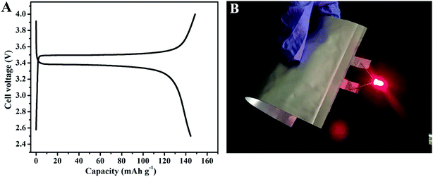
Developing flexible GPEs with high-performance has been regarded as one of the main challenges for flexible batteries. To explore the potential application of IPN-GPE 3/7 in flexible devices, the pouch type batteries using IPN-GPE 3/7 as electrolyte were assembled. The electrochemical activity of Li/IPN-GPE 3/7/LiFePO4 pouch cell was tested at 40 °C with a charge/discharge current density of 0.1C (Fig. 6A). The cells exhibit very stable charge/discharge behavior, and a discharge capacity of about 142 mA h g−1 can be achieved. Fig. 6B shows that a pouch cell based on IPN-GPE 3/7 can light up a commercial red LED even under bent condition. It implies that IPN-GPE 3/7 can efficiently prevent internal short-circuit when mechanical abuse and afford a potential application in large scale deformable lithium batteries. Moreover, after storing in the inert atmosphere for around two months, the macro morphology of IPN-GPE 3/7 remains steady without crarizonae on the surface (Fig. S3A†). Nevertheless, when MHBIm-TFSI is replaced by PEGMA with other contents changeless, cracking phenomenon is observed on the obtained electrolyte membrane (Fig. S3B†). The above-mentioned results demonstrate that IPN-GPE 3/7 can maintain excellent stability even under a significant shape deformation, and sustain tight adhesion with electrodes, resulting in improved electrochemical performance and safety for flexible LIBs.
4. Conclusions
In summary, a novel cross-linked gel polymer electrolyte IPN-GPE was successfully synthesized through a facile in situ thermal induced free radical polymerization technique. The IPN-GPE displayed a considerable electrochemical stability window of 5 V vs. Li+/Li and high ionic conductivity up to 1.3 × 10⁻³ S cm−1 at 30 °C. Additionally, the IPN-GPE exhibited both interfacial compatibility toward LiFePO4 and lithium electrodes. Together with its excellent flexibility, cross-linked structure, good mechanical robustness as well as thermal stability (over 310 °C), Li/LiFePO4 cells using IPN-GPE as electrolyte represent superior charge/discharge performance, excellent cycling stability and rate capability. The simple, easily controlled and low-cost in situ synthesis process as well as the outstanding performance of IPN-GPE make it one of the most promising solid polymer electrolyte candidates to replace conventional liquid electrolytes for next generation rechargeable lithium-based batteries with highly promoted electrochemical performance and safety.Conflicts of interest
The authors declare no competing financial interest.Acknowledgements
Y. C. thanks for support from National Science Fund for Distinguished Young Scholars (51425304). K. Y. thanks for the support from the Natural Science Foundation of China (21704038, 51763018), the Natural Science Foundation of Jiangxi Province (20171ACB21009) and National Postdoctoral Program for Innovative Talents (BX201700112). D. Z. thanks for the support from the Natural Science Foundation of China (21602150).References
- G. Zhou, F. Li and H. Cheng, Energy Environ. Sci., 2014, 7, 1307–1338 CAS.
- H. Nishide and K. Oyaizu, Science, 2008, 319, 737–738 CrossRef CAS PubMed.
- M. Armand and J. M. Tarascon, Nature, 2008, 451, 652–657 CrossRef CAS PubMed.
- J. Goodenough and Y. Kim, Chem. Mater., 2010, 22, 587–603 CrossRef CAS.
- B. Scrosati, J. Hassoun and Y. Sun, Energy Environ. Sci., 2011, 4, 3287–3295 CAS.
- N. Choi, Z. Chen, S. Freunberger, X. Ji, Y. Sun, K. Amine, G. Yushin, L. Nazar, J. Cho and P. Bruce, Angew. Chem., Int. Ed., 2012, 51, 9994–10024 CrossRef CAS PubMed.
- M. Koo, K. Park, S. Lee, M. Suh, D. Jeon, J. Choi, K. Kang and K. Lee, Nano Lett., 2012, 12, 4810–4816 CrossRef CAS PubMed.
- L. Hu, H. Wu, F. La Mantia, Y. Yang and Y. Cui, ACS Nano, 2010, 4, 5843–5848 CrossRef CAS PubMed.
- M. Wu, J. Lee, P. Chiang and J. Lin, J. Mater. Sci., 2007, 42, 259–265 CrossRef CAS.
- A. Goyal, A. Reddy and P. Ajayan, Small, 2011, 7, 1709–1713 CrossRef CAS PubMed.
- S. Chew, S. Ng, J. Wang, P. Novak, F. Krumeich, S. Chou, J. Chen and H. Liu, Carbon, 2009, 47, 2976–2983 CrossRef CAS.
- J. Wang, C. Zhong, S. Chou and H. Liu, Electrochem. Commun., 2010, 12, 1467–1470 CrossRef CAS.
- N. Li, Z. Chen, W. Ren, F. Li and H. Cheng, Proc. Natl. Acad. Sci. U. S. A., 2012, 109, 17360–17365 CrossRef CAS PubMed.
- L. Noerochim, J. Wang, S. Chou, D. Wexler and H. Liu, Carbon, 2012, 50, 1289–1297 CrossRef CAS.
- K. Choi, S. Cho, S. Kim, Y. Kwon, J. Kim and S. Lee, Adv. Funct. Mater., 2014, 24, 44–52 CrossRef CAS.
- J. Zhang, J. Zhao, L. Yue, Q. Wang, J. Chai, Z. Liu, X. Zhou, H. Li, Y. Guo, G. Cui and L. Chen, Adv. Energy Mater., 2015, 5, 1501082 CrossRef.
- L. Noerochim, J. Wang, D. Wexler, M. Rahman, J. Chen and H. Liu, J. Mater. Chem., 2012, 22, 11159–11165 RSC.
- Z. Zhu, M. Hong, D. Guo, J. Shi, Z. Tao and J. Chen, J. Am. Chem. Soc., 2014, 136, 16461–16464 CrossRef CAS PubMed.
- X. Zeng, Y. Yin, N. Li, W. Du, Y. Guo and L. Wan, J. Am. Chem. Soc., 2016, 138, 15825–15828 CrossRef CAS PubMed.
- H. Zhang, C. M. Li, M. Piszcz, E. Coya, T. Rojo, L. M. Rodriguez-Martinez, M. Armand and Z. Zhou, Chem. Soc. Rev., 2017, 46, 797–815 RSC.
- P. Kritzer, J. Power Sources, 2006, 161, 1335–1340 CrossRef CAS.
- E. Quartarone and P. Mustarelli, Chem. Soc. Rev., 2011, 40, 2525–2540 RSC.
- T. Sugimoto, Y. Atsumi, M. Kikuta, E. Ishiko, M. Kono and M. Ishikawa, J. Power Sources, 2009, 189, 802–805 CrossRef CAS.
- A. Lewandowski and A. Swiderska-Mocek, J. Power Sources, 2009, 194, 601–609 CrossRef CAS.
- M. Armand, F. Endres, D. MacFarlane, H. Ohno and B. Scrosati, Nat. Mater., 2009, 8, 621–629 CrossRef CAS PubMed.
- Y. Zhu, F. Wang, L. Liu, S. Xiao, Z. Chang and Y. Wu, Energy Environ. Sci., 2013, 6, 618–624 CAS.
- P. Sun, Y. Liao, H. Xie, T. Chen, M. Rao and W. Li, J. Power Sources, 2014, 269, 299–307 CrossRef CAS.
- Q. Lu, Y. He, Q. Yu, B. Li, Y. Kaneti, Y. Yao, F. Kang and Q. Yang, Adv. Mater., 2017, 29, 1604460 CrossRef PubMed.
- H. Kataoka, Y. Saito, T. Sakai, E. Quartarone and P. Mustarelli, J. Phys. Chem. B, 2000, 104, 11460–11464 CrossRef CAS.
- M. Liu, D. Zhou, Y. He, Y. Z. Fu, X. Qin, C. Miao, H. D. Du, B. Li, Q. Yang, Z. Lin, T. Zhao and F. Kang, Nano Energy, 2016, 22, 278–289 CrossRef CAS.
- H. Ha, E. Kil, Y. Kwon, J. Kim, C. Lee and S. Lee, Energy Environ. Sci., 2012, 5, 6491–6499 CAS.
- M. Imperiyka, A. Ahmad, S. Hanifah and F. Bella, Phys. B, 2014, 450, 151–154 CrossRef CAS.
- M. Susan, T. Kaneko, A. Noda and M. Watanabe, J. Am. Chem. Soc., 2005, 127, 4976–4983 CrossRef CAS PubMed.
- J. Chai, J. Zhang, P. Hu, J. Ma, H. Du, L. Yue, J. Zhao, H. Wen, Z. Liu, G. Cui and L. Chen, J. Mater. Chem. A, 2016, 4, 5191–5197 CAS.
- P. Han, Y. Zhu and J. Liu, J. Power Sources, 2015, 284, 459–465 CrossRef CAS.
- G. Lane, Electrochim. Acta, 2012, 83, 513–528 CrossRef CAS.
- C. Arbizzani, G. Gabrielli and M. Mastragostino, J. Power Sources, 2011, 196, 4801–4805 CrossRef CAS.
- J. Shin, W. Henderson and S. Passerini, J. Electrochem. Soc., 2005, 152, A978–A983 CrossRef CAS.
- M. Li, L. Yang, S. Fang, S. Dong, S. Hirano and K. Tachibana, J. Power Sources, 2011, 196, 8662–8668 CrossRef CAS.
- A. Padhi, K. Nanjundaswamy and J. Goodenough, J. Electrochem. Soc., 1997, 144, 1188–1194 CrossRef CAS.
- W. Ye, J. Zhu, X. Liao, S. Jiang, Y. Li, H. Fang and H. Hou, J. Power Sources, 2015, 299, 417–424 CrossRef CAS.
- H. Jeong, D. Kim, Y. Jeong and S. Lee, J. Power Sources, 2010, 195, 6116–6121 CrossRef CAS.
Footnotes |
| † Electronic supplementary information (ESI) available. See DOI: 10.1039/c7ra10268b |
| ‡ These authors contributed equally to this work. |
| This journal is © The Royal Society of Chemistry 2017 |


