Highly integrated catalytic burner with laser-additive manufactured manifolds
J.
Meißner
 *a,
S.
Weiske
 a,
D.
Faidel
b,
A.
Tschauder
a,
R. C.
Samsun
a,
D.
Faidel
b,
A.
Tschauder
a,
R. C.
Samsun
 a,
J.
Pasel
 a,
R.
Peters
 a and
D.
Stolten
 ac
ac
aForschungszentrum Jülich GmbH, IEK-3: Institute of Electrochemical Process Engineering, Jülich, Germany. E-mail: j.meissner@fz-juelich.de
bForschungszentrum Jülich GmbH, ZEA-1: Central Institute for Engineering and Technology, Jülich, Germany
cChair for Fuel Cells,, RWTH Aachen University, Aachen, Germany
First published on 8th May 2017
Abstract
This paper describes a highly integrated catalytic burner for auxiliary power units based on PEM-fuel cells. The generated heat is used by an integrated heat-exchanger system. The feasibility is verified by fluid-dynamic calculations. An innovative approach to develop complex reactors for demanding requirements defined by the application is presented.
Introduction
Forschungszentrum Jülich's institute Electrochemical Process Engineering – Fuel Processing and Systems (IEK-3) is developing a diesel-/kerosene-based fuel cell auxiliary power unit (APU) for the on-board power supply of trucks and aircraft. The investigation of the system by means of modeling and experiments was described by Samsun et al.1–3 The catalytic burner has the task of completely converting any unconverted compounds (hydrogen, carbon monoxide, and methane) and providing process heat in the system. For reasons of efficiency, the catalytic burner must be as closely integrated in the system configuration of the hydrocarbon-based fuel cell APU as possible.A large number of publications describe fuel processing systems in which catalytic burners provide the reforming reactions with process heat that is then harnessed by external heat exchangers. Gardemann et al.4 describe a fuel-processing system in which the catalytic burner was combined with external heat exchangers to exploit the combustion enthalpy for the process. Engelhardt et al.5,6 intend to use the heat content of the anode off-gas to heat a steam reformer. However, their initial system – which makes use of a diesel-based fuel cell APU – flares off the anode off-gas instead of using it thermally. In their model, Ellamla et al.7 do not include a reactor for further thermal exploitation of unconverted components in the anode off-gas of the fuel cell. Only the waste heat from the anode off-gas is used. Nomnqa et al.8 describe a system for supplying residential buildings with energy. They use the anode off-gas of an HT PEM FC in a catalytic burner in order to provide the process heat for methane steam reforming. In another heat exchanger, downstream from the burner, the hot off-gas is used to heat service water. In their simulation of a micro cogeneration system, Zuliani et al.9 mix the anode off-gas with natural gas. This mixture is combusted in order to provide the steam reformer with process heat via external heat exchangers in the system. In a process simulation of an HT PEM system with a natural-gas reformer, Ersöz et al.10 describe a catalytic burner that thermally exploits the anode off-gas and uses the hot off-gas to preheat the water, air, and natural-gas feed for the reformer. A comparable system is used by Najafi et al.11 and Mamaghani et al.12 in their models.
Numerous publications investigated extensively CFD modeling of oxidation reactions of hydrogen,13–15 carbon monoxide16 and methane17 or mixtures of two of the components.18–20 The CFD models described in these publications differ mainly in the level of details. In some of them it goes down to the level of modeling the individual elementary reactions of the reaction systems. This enables a fundamental analysis of the reaction behavior in the reaction systems. For CFD modeling within the development of reactors for a fuel cell based APU system the solution of such complex reaction system is not feasible. Scharf21 proposed simplified CFD models for the chemical reaction systems in the reactor. For the basic chemical reactions in the CAB as given in Table 1 the correlations of the Fluent model library were utilized. These correlations were adapted to correspond with experimental results achieved with CAB 2.22
| Reaction | ΔHR |
|---|---|
| H2 + 0.5 O2 → H2O | −802 kJ mol−1 |
| CH4 + 2 O2 → CO2 + 2H2O | −242 kJ mol−1 |
| CO + 0.5 O2 → CO2 | −283 kJ mol−1 |
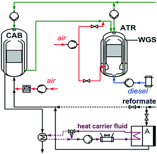
Fig. 1 shows the usual integration of a catalytic burner (CAB) in a fuel processing system using an HT PEM fuel cell as described by Samsun et al.23 In it, the catalytic burner is equipped with an internal heat exchanger and combined in the system with further external heat exchangers. Table 1 gives the three reactions taking place in the catalytic burner. During normal operation of the system, the low-calorific anode off-gas (≈20–30 kJ mol−1) of the fuel cell stack serves as the educt. During start-up, power-down, or malfunctions in the system, the product gas from the reformer cannot be directly transferred into the fuel cell anode due to its poor quality (too much CO, deactivating by-products). For this reason, the fuel cell stack is bypassed. In these operating conditions, the catalytic burner must also be capable of converting the high-calorific reformate (≈80 kJ mol−1).22,24 The advantages of this manner of integrating a CAB in a system are a comparatively simple technical design of the device, low weight, and easy manufacture. From the point of view of the fuel cell system, the disadvantage is the need for up to three more external components for media preheating and HT PEM FC stack heating. Due to the multitude of components, the need for space is very great and the weight of the whole system due to the components themselves and the required pipework connecting the components with each other is very high.
This also causes high heat losses in the system. In this design, the autothermal reformer (ATR) is provided with steam from the CAB. Additionally, there are two air flows between which the reaction air for the ATR can be divided. The first partial air flow is mixed with the steam flow from the CAB, and the second air flow is directly introduced into the mixing chamber of the ATR by the annular air injector. This operation of the reformer was described by Pasel et al.25
Reactor design and model development
The optimization of Jülich's previous reactor generations focused on reducing weight and volume as well as improving vaporization. Thus, the volume-related power density was increased by 200% to 5.8 kWth,ATR l−1 and the mass-related power density by 160% to 4.2 kWth,ATR kg−1 from CAB 2 to CAB 4.22 The next step, described here, focuses on increasing efficiency and reducing the complexity of the system as a whole, i.e. the number of system components.Reactor design
The catalytic burner has a central task in achieving a simplification of the system. In addition to the previous requirements set for the CAB, namely the complete conversion of H2, CH4, and CO when operating on anode off-gas or reformate and the internal production of steam for the ATR, the following new requirements for the catalytic burner were defined:• It must be possible to add air to the internal steam generator in order to achieve independence from the position of the device. The air in this case serves as a carrier gas to carry any water droplets that have not been vaporized. The added air is a partial flow of the reaction air for the ATR. This media flow should reach a temperature of approximately 200 °C.
• It should also be possible to heat the second volume flow necessary for autothermal reforming (cf.Fig. 1) to a temperature of 200 °C. This flow is added to the reformer via the annular air injector.
• The HT PEM stack in the system is to be heated and temperature-controlled by means of a heat carrier fluid. This heat carrier fluid is to be heated in an internal heat exchanger of the catalytic burner using the waste heat from the burner off-gas. This means that one control valve in the oil circulation system can be omitted. During normal operation, the heat carrier fluid should have a temperature of 160–170 °C.
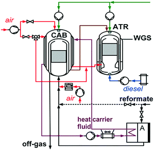
• From these requirements, the system shown in Fig. 2 of a diesel-/kerosene-based HT PEM fuel cell APU was defined. It is a design of an APU system of a much higher grade of integration. The challenge is to plan and design such a highly integrated reactor so that it can be manufactured.
In designing a catalytic burner able to fulfil the requirements defined above, the well-established concentric structure of the annular gaps of previous generations of catalytic burners was incorporated. Water is sprayed onto a hemispherical head and flows in co-current flow parallel to the hot off-gas through an annular gap while it is completely vaporized. This concept was described in detail by Meißner et al.22,24
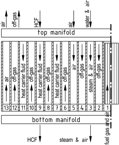
The flow configuration through CAB 5 is schematically shown in Fig. 3. The media flow inlets and outlets are shown with their direction of flow at the top and bottom manifolds. The flow channels are numbered from the inside to the outside (from right to left in the figure). The first channel symbolically represents the cylindrical core of the reactor, with the mixing chamber and the monolithic catalyst.
The mixture of fuel gas and combustion air (1) is fed in downstream from the mixing chamber, axially to the monolithic catalyst. In the top manifold, the hot off-gas is redirected and flows towards the bottom through annular gaps (2) and (4).
A water–steam–air mixture flows parallel to this through annular gap (3) and is withdrawn in the bottom manifold. In the bottom manifold, the off-gas is again redirected, flows through channels (6), (8), (10), and (12) back to the top, and is withdrawn through a connection in the top manifold. The heat carrier fluid is fed in through the top manifold and conducted in counterflow to the off-gas through annular gaps (7), (9), and (11). Combustion air in the system reserved for the ATR is fed in for preheating into annular gap (5) in the top manifold, redirected in the bottom manifold and conducted to the top through the outermost annular gap (13). The air is then withdrawn in the upper manifold. By placing a channel for preheating the ATR combustion air – channel (13) – on the outside, the heat losses of the reactor can be reduced to a minimum. The wall temperature of the outer pressure jackets thus remains well below 400 °C, resulting in very moderate requirements for the choice of materials in the reactor.
Fig. 4 shows a sectional view through the YZ plane of the bottom manifold for CAB 5. The numbers of the annular gaps are identical to those in Fig. 3. The feed for the combustion air (1) is axial to this. The fuel gas is concentrically fed into the mixing chamber via a circle of holes and there mixed with the combustion air – after the latter has passed through the diffuser – and homogenized. The fuel-gas–air mixture is then converted at the monolithic catalyst. Feeding the media for combustion is effected in a way that avoids preheating by other media flows in order to prevent homogeneous combustion in the area of the mixing chamber. The steam–air mixture (3) is withdrawn through the widened annular gap (dark blue). In order to realize the multitude of crossings of media flows and redirections, the design includes radial channels between the annular gaps with rotational symmetry. On the left-hand side, the sectional view shows one of 15 radially deployed channels for air redirection (light blue) from annular gap (5) to annular gap (13). The right-hand side shows a section of the redirection channels of the off-gas (orange) from annular gaps (2) and (4) into annular gaps (6), (8), (10), and (12). The heat carrier fluid (light green) is brought together from annular gaps (7), (9), and (11). The heat carrier fluid is then collected in a concentric channel and fed into the heat carrier fluid circulation system.
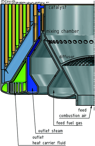 | ||
| Fig. 4 Sectional view through the YZ plane of the bottom manifold of CAB 5; the enumeration of the annular gaps corresponds to that in Fig. 3. | ||
The new incorporation of the highly integrated catalytic burner, as shown in Fig. 2, makes various external components in the APU system superfluous. Three plate heat-exchangers and the complete pipework between them can be removed. It saves a conservatively estimated installation space of 20 l and 14 kg in system weight. Further 15 l installation space and 10 kg system weight are saved as the high temperature control valve in the heat carrier fluid circuit (cf.Fig. 1) can be omitted. However, the volume-related power density of the CAB 5 itself decreases in comparison to CAB 4 by about 45% to 2.6 kWth,ATR l−1 and the mass-related power density by about 55% to 2.3 kWth,ATR kg−1. The estimated total weight of the CAB 5 is about 12 kg and the required installation space is about 12 l. Also from the system design engineering point of view the conventional approach (cf.Fig. 1) is hardly feasible. During the preheating operation of the stack when the CAB is operated with reformate the off-gas of the burner reaches a temperature >600 °C. The temperature of the heat carrier fluid in the heat exchanger operated with the off-gas of the catalytic burner would exceed its tolerable limits. The heat carrier fluid would begin to decompose and damage the cooling circuit of the APU, including the fuel cell stack. In the revised system design with CAB 5 it can be ensured, that the heat carrier fluid exceeds in no point of time its tolerable limits.
Manufacturing technology
The required complex geometries of the top and bottom manifolds including undercuts and hidden channels cannot be produced using conventional manufacturing technologies. In order to manufacture a component of the geometry shown in Fig. 4, laser-additive manufacturing technology was used and the geometry of the manifolds was adapted to the requirements of this manufacturing technology. The laser-additive manufacturing technology offers the opportunity to optimize the design of two key components – the top and the bottom manifold – of the CAB 5. The cost factor and building time factor should be considered for the entire production chain of the designed assembly group.26 In this case the assembly group incorporating two laser-additive manufactured parts for a single device is not necessarily more expensive than conventional production. The advantages for the overall APU-system that can be achieved e.g. less weight and a less complex geometry achieved by this technology outweighs the disadvantages of the laser-additive manufacturing technology significantly.27–30 Although the laser-additive manufacturing-technology is still a production technology under intense development it is already used in the aerospace industry for small to medium-sized production lot sizes.31 There are already some initial approaches to implement this technology for mass production.32 One considerable disadvantage of laser-additive manufacturing is that flat surfaces cannot be produced without support structures, which cannot be subsequently removed from the hidden channels. In order to avoid the necessity for such support structures in the component, no flat geometries were used at all. All walls have a material thickness of approximately 1 mm, non-vertical walls have inclines of approximately 60°, and in no place were stretches of more than 5 mm freely spanned. Stretches resulting from the channels and feeds were designed to be curved.A modified M2 cusing machine from Concept Laser GmbH was used to manufacture the manifold. These modifications of the laser-additive manufacturing-machine were described by Faidel et al.33,34 The part was produced using a stainless-steel powder, material number 1.4876 (corresponds to Alloy 800H). The manufacturing parameters were:
• Focused laser beam diameter: 100 μm (“donut” type)
• Laser power: 125 W
• Laser scanner velocity: 450 mm s−1
• Overlap: 40 μm
• Shielding gas: nitrogen, residual oxygen <0.1%
The resolution of the laser-additive manufacturing-process primarily depends on the laser beam diameter, layer thickness and grain size of the metal-powder used to build the part. The smaller these parameters the better is the resolution of the process. An increase of the build rate results in a reduced resolution of the process.35 With a beam diameter of 100 μm, average powder grain size of 50 μm and layer thickness of 25–50 μm it is possible to build parts with minimal wall thickness of 150–200 μm. As the wall thickness of the manifolds produced is about 1 mm the resolution of the laser-additive manufacturing process is sufficient. The surface roughness Ra is in this case about 20–40 μm and cannot be really improved without mechanical finish. Only at the joint patches of the manifolds a partial CNC cutting is required to achieve the necessary calibration of the diameter and the surface roughness.
This bottom manifold was generatively manufactured with the manufacturing parameters mentioned above, over a period of approximately 65 hours.
Table 2 summarizes the advantages and disadvantages of conventional reactor technology for catalytic burners and the new, highly integrated design of a catalytic burner as shown here.
| Conventional reactor technology | Highly integrated reactor | |
|---|---|---|
| Advantages | • Simple design• Light reactor • Internal steam generator |
• Internal steam generator, optional ATR reaction air as carrier gas• Provision of preheated reaction air for the reformer • Integration of heat carrier fluid circulation system for stack preheating and temperature control • High system power density • Reactor independent of position in the system • No need for valve in the heat carrier fluid circulation system |
| Disadvantages | • Up to two additional components for air preheating necessary• High heat losses • Heat recovery critical |
• More complex design• Time-consuming manufacture • Complex manufacturing technology |
CFD model
The reactor concept of the highly integrated device was validated using a CFD analysis. The formation of a mixture of combustion air with the combustible compounds of the anode off-gas from the fuel cell for the heterogeneously catalyzed combustion reaction was separately examined and optimized and is not discussed in detail here. The mixture formation was modelled separately to ensure a homogenous fuel/air mixture. This homogenous mixture will then react on the catalytic surface where total oxidation of all three combustible compounds (cf.Table 1) is achieved.The principle for the CFD validation to predict experimental results was comprehensively described by Scharf.21,36 The results of this work provide conditions for the analysis of heat transport in the form of inlet temperatures and compositions.
Particularly the heat transfer between the media flows was investigated. The only medium releasing heat here is the hot off-gas from catalytic combustion. The media absorbing heat are the water–steam–air mixture, the ATR combustion air, and the heat carrier fluid. The calculation was conducted by means of the ANSYS Fluent software.
• The turbulence of the flow was modeled using the k–ε model.
• In order to model the combustion reactions, the various substances and molecules must be introduced. After computationally separating the substance flow into its individual components, the following equation is solved for each substance:
 | (1) |
 represents diffusive mass flow, which can be calculated using Fick's laws of diffusion. In turbulent flows, diffusive mass flow is viewed as negligible since convective mass transport is dominant. Ri describes the chemical source term.37
• The combustion reactions themselves were modeled using the laminar finite-rate model.
• The catalyst was defined as a porous flow body; the parameters were adopted from Scharf21 and Sinha.38
• Water injection was modeled using ANSYS Fluent's discrete phase model (DPM). The water injection was effected by a point source, as validated by Scharf.21
The computational mesh for modeling the heat transport in the catalytic burner is displayed in Fig. 5. The corresponding statistical quality factors for the computational mesh are given in Table 3. In order to be able to use the described computational grid to analyze heat transport in the reactor, modeling was simplified considerably so that usable computation times could be achieved. In this model, the bottom of the monolith that was coated with catalyst and used for catalytic combustion represents the inlet surface into the model of the combusted, hot off-gas. This is based on the assumption that combustion occurs at the inlet surface and is complete and homogeneous. This simplification disregards the temperature profile formed in the monolith. This assumption is acceptable, since a detailed analysis by Weiske39 of the mixture formation and the reactions were performed in a prior simulation step, where both sections of the catalytic proved to function ideally. A further simplification concerns the modeling of water injection in the catalytic burner. The injection nozzle is not modeled in detail here since it would require a further, elaborate grid of the very fine nozzle geometry.
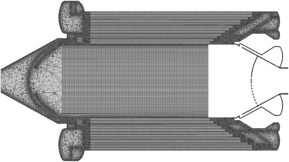 | ||
| Fig. 5 Sectional view through the YZ plane of the mesh used for the calculation of the heat transport in CAB 5. | ||
| Number of elements | Number of nodes | Skewness | Ortho. quality |
|---|---|---|---|
| <40 × 106 | <11 × 106 |
![[S with combining macron]](https://www.rsc.org/images/entities/i_char_0053_0304.gif) = 0.31 = 0.31 |
Ō = 0.74 |
| σ s = 0.21 | σ o = 0.18 |
The sensitivity of the grid has not been assessed due to the time-consuming calculations. It was relied on the computational experience with the meshing of similar CFD models of APU components by Porš,40 Scharf21 and Krupp.41
Results and discussion
CFD validation of the reactor concept
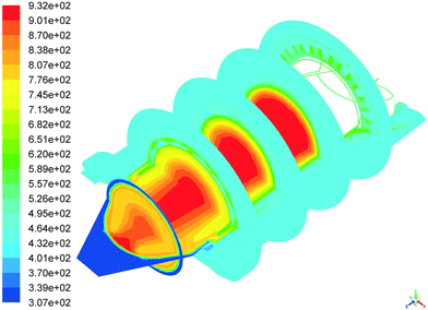
As a validation of the reactor concept, this publication describes the simulation of regular operation with anode off-gas. Fig. 6 shows a representation of the temperature profile in several planes through the reactor. The reactor is pictured lying on its side. The top manifold is located on the left-hand side, and the bottom manifold on the right-hand side. The water to be vaporized is injected from the top. The fuel gas and combustion air are added axially from the bottom; they react at the monolithic catalyst and increase the temperature to approximately 660 °C. This media flow of hot off-gas is the heat source for the internal heat exchangers. The very rapid homogenization of the temperatures inside the annular gaps in the radial direction is clearly visible. From the center of the monolith, the temperature decreases particularly sharply in the first off-gas flow channel. The vaporization of the water removes a great deal of thermal energy from the hot off-gas, cooling it down. All remaining media flows in the other channels have comparable temperatures, and can therefore not be distinguished in the figure.It appears as a large area with a homogeneous temperature of approximately 170 °C. This temperature corresponds to the inlet temperature of the heat carrier fluid, which thus has a great influence on the homogenization of the media temperature in the catalytic burner. In the heat carrier fluid circuit no dangerous hot spots where observed that could lead to a decomposition of the heat carrier fluid.
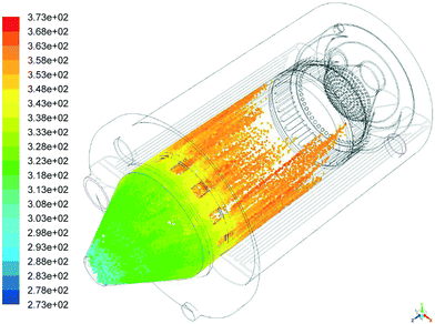
The distribution of the water droplets with the corresponding temperature is depicted in Fig. 7. The reactor is again pictured lying on its side. The top manifold is located on the left-hand side, the bottom manifold on the right-hand side. The cold water to be vaporized is injected onto the hemispherical head from the top. The injected amount of 3 kg h−1 corresponds to 70% of the ATR water demand of approximately 4.2 kg h−1 at nominal load of the APU. The water to be vaporized then flows down in parallel through the annular gap (3), framed by the hot off-gas in annular gaps (2) and (4), and vaporizes. The particle distribution shows the maximum distance that the injected water droplets travel inside the reactor before being vaporized. This maximum distance is approximately at the level of the inlet plane of the monolith (not shown in the figure). The flow channel of the steam thus offers sufficient safety distance from the latest vaporization of the water droplets until the outlet of the steam from the reactor. The heat exchanger surface of the water cycle is suitably dimensioned.
The most important mode of operation of the catalytic burner is normal operation using anode off-gas. During this operating state, the operating temperature of the HT PEM fuel cell stack is 160 °C, with a temperature increase of 10 K over the entire fuel cell stack being permissible. Thus, the heat carrier fluid has an inlet temperature of 170 °C during regular operation.
Table 4 gives an overview of the inlet and outlet temperatures and the thermal power of the individual flows that is absorbed or released, as determined by CFD simulation. The temperature of the heat carrier fluid was calculated separately to check the heat balance. Due to the presence of backflows and resulting convergence issues during simulation, the temperature reading for this parameter contained inaccuracies. The high heat capacity of heat transfer fluid resulted in a very slight temperature increase (ΔT = 0.7 K) of the heat transfer fluid during operation with anode off-gas. This is advantageous for system design, since this medium must be cooled anyway before the flowing into the stack for stack cooling. The temperature of 230.8 °C at the water cycle outlet exceeds the target of 200 °C. In contrast, the air to be preheated only reaches 176.9 °C. The targeted process parameters are thus not quite fulfilled. However, the resulting deviation does not cause any difficulties for the stable operation of the fuel cell system. For the ATR experimental results are published with a reduced temperature for the air stream of 180 °C and 200 °C steam/air-temperature.42 A stable operation of the ATR was demonstrated. An increased temperature of about 230 °C for the steam fed to the ATR helps to increase the temperature in the ATR mixing chamber and thereby favors the ignition of an exothermic homogeneous pre-reaction between some of the prevailing oxygen and hydrocarbon molecules contained in the fuel. This improves the fuel evaporation in the ATR and further stabilizes the operation of this reactor. An option of securing the process parameters for the reformer is to mix the air and the steam after they have exited the catalytic burner. Another option for guaranteeing suitable operating conditions for the reformer is to add a larger amount of air or the entire volume of air for the ATR through the water cycle of the catalytic burner, i.e. into annular gap (3) – cf.Fig. 3 and 4.
| Media flow | ṁ kg h−1 | T in °C | T out °C | T aim °C | Δ![[Q with combining dot above]](https://www.rsc.org/images/entities/i_char_0051_0307.gif) kW kW |
|---|---|---|---|---|---|
| Air 70% of ATR air demand to ATR annular air injector | 5.6 | 60.0 | 176.9 | 200 | 0.2 |
| Off-gas | 19.3 | 658.9 | 182.9 | −3.30 | |
| Heat carrier fluid | 1447.4 | 170 | 170.9 | 0.9 | |
| Water cycle 70% ATR water demand + 30% ATR air demand | 5.4 | 50.0 | 230.8 | 200 | 2.3 |
For the preheating process using reformate, the CFD model showed that the targeted temperatures of the media flows are achieved as well. More than 81.5–86.2% of the thermal power is needed for preheating the heat carrier fluid.
Finally, with regard to fluid mechanics, the catalytic burner reactor concept has to be examined for pressure losses. The pressure losses are determined by finding the difference between the average static pressures of the inlets and outlets. It is always the maximum pressure loss that is considered. Due to the significantly higher air mass flow during the preheating phase (λ = 3.5), the larger pressure loss is on the air side at this operating point. The results of the pressure loss calculations are listed in Table 5. The threshold value for pressure losses of 80 mbar prescribed by the APU system is not reached in the simulations, so that this analysis shows the functional feasibility of the reactor concept.
| Operating state | Off-gas [mbar] | Air [mbar] | Heat carrier fluid [mbar] | Steam pathway [mbar] |
|---|---|---|---|---|
| Anode off-gas | 11.9 | 1.60 | 20.3 | 12.5 |
| Reformate | 57.1 | 1.04 | 20.7 | 9.1 |
Conclusions
Laser-additive manufacturing of a top and bottom manifold with elaborate geometries of integrated flow redirection for a catalytic burner enabled comprehensive heat integration into one single device. Four external components – three plate heat exchangers, a high-temperature control valve and the required piping – could be eliminated. The integration of the above mentioned functions into a single device results in a reduction of the related volume from 41 l to 11 l, a reduction of about 70%. The weight reduces from 30 kg to 12 kg by about 60%. The feasibility of a highly integrated catalytic burner for a diesel- or kerosene-based HT PEM FC APU was validated using fluid-dynamical analyses (CFD). The feasibility of the laser-additive manufacture of both manifolds was demonstrated. Based on the concept shown here, the catalytic burner CAB 5 will be manufactured in the course of 2017 to validate the feasibility study shown here using experimental results.Nomenclature
List of abbreviations
| APU | Auxiliary power unit |
| ATR | Autothermal reformer/autothermal reforming |
| CAB | Catalytic burner |
| CFD | Continuous fluid dynamics |
| DPM | Discrete phase model |
| HCF | Heat carrier fluid |
| HSR | Heated steam reforming |
| HT PEM | High temperature polymer electrolyte fuel cell |
| WGS | Water-gas shift reactor |
List of symbols
Indexes
| aim | Target value |
| e | Electrical |
| I | Component |
| in | Inlet |
| out | Outlet |
| th | Thermal |
| V | Volume-related |
| W | Weight-related |
Acknowledgements
The authors would like to thank their colleagues from the Central Institute for Engineering and Technology (ZEA-1) at Jülich research center for the intensive exchange on the laser additive manufacturing technology and the joining technology.References
- R. C. Samsun, C. Krupp, A. Tschauder, R. Peters and D. Stolten, J. Power Sources, 2016, 302, 315–323 CrossRef CAS.
- R. C. Samsun, J. Pasel, R. Peters and D. Stolten, Int. J. Hydrogen Energy, 2015, 40, 6405–6421 CrossRef CAS.
- R. C. Samsun, in Brennstoffzellensysteme in der Luftfahrt, ed. R. Peters, Springer, Berlin Heidelberg, 2015, ch. 7, pp. 281–332, DOI:10.1007/978-3-662-46798-5_7.
- U. Gardemann, M. Steffen and A. Heinzel, Int. J. Hydrogen Energy, 2014, 39, 18135–18145 CrossRef CAS.
- P. Engelhardt, M. Maximini, F. Beckmann and M. Brenner, Int. J. Hydrogen Energy, 2012, 37, 13470–13477 CrossRef CAS.
- P. Engelhardt, M. Maximini, F. Beckmann, M. Brenner and O. Moritz, Int. J. Hydrogen Energy, 2014, 39, 18146–18153 CrossRef CAS.
- H. R. Ellamla, P. Bujlo, C. Sita and S. Pasupathi, Chem. Eng. Sci., 2016, 154, 90–99 CrossRef CAS.
- M. Nomnqa, D. Ikhu-Omoregbe and A. Rabiu, Int. J. Chem. Eng., 2016, 2016, 14 Search PubMed.
- N. Zuliani and R. Taccani, Appl. Energy, 2012, 97, 802–808 CrossRef CAS.
- A. Ersöz and A. Sayar, Int. J. Hydrogen Energy, 2015, 40, 14469–14482 CrossRef.
- B. Najafi, A. Haghighat Mamaghani, F. Rinaldi and A. Casalegno, Appl. Energy, 2015, 147, 582–592 CrossRef.
- A. Haghighat Mamaghani, B. Najafi, A. Casalegno and F. Rinaldi, Appl. Therm. Eng., 2016, 99, 1201–1211 CrossRef.
- J. C. G. Andrae and P. H. Björnbom, AIChE J., 2000, 46, 1454–1460 CrossRef CAS.
- W. R. Williams, C. M. Marks and L. D. Schmidt, J. Phys. Chem., 1992, 96, 5922–5931 CrossRef CAS.
- J. Hua, M. Wu and K. Kumar, Chem. Eng. Sci., 2005, 60, 3497–3506 CrossRef CAS.
- P. Aghalayam, Y. K. Park and D. G. Vlachos, Proc. Combust. Inst., 2000, 28, 1331–1339 CrossRef CAS.
- J. Li, S. K. Chou, W. M. Yang and Z. W. Li, Chem. Eng. J., 2009, 150, 213–222 CrossRef CAS.
- D. Jiang, W. Yang and J. Teng, Int. J. Hydrogen Energy, 2015, 40, 5210–5220 CrossRef CAS.
- W. Wang, Z. Zuo, J. Liu and W. Yang, Int. J. Hydrogen Energy, 2016, 41, 20744–20752 CrossRef CAS.
- J. Mantzaras, Catal. Today, 2006, 117, 394–406 CrossRef CAS.
- F. Scharf, Strömungsmechanische Modellierung eines Brenngaserzeugungssystems, Doctoral Thesis edn, RWTH Aachen University, Jülich, 2012 Search PubMed.
- J. Meißner, J. Pasel, R. C. Samsun, F. Scharf, C. Wiethege and R. Peters, Int. J. Hydrogen Energy, 2014, 39, 4131–4142 CrossRef.
- R. C. Samsun, J. Pasel, H. Janßen, W. Lehnert, R. Peters and D. Stolten, Appl. Energy, 2014, 114, 238–249 CrossRef CAS.
- J. Meißner, J. Pasel, R. C. Samsun, R. Peters and D. Stolten, Fuel Cells, 2015, 15, 15–26 CrossRef.
- J. Pasel, R. C. Samsun, A. Tschauder, R. Peters and D. Stolten, Appl. Energy, 2015, 150, 176–184 CrossRef CAS.
- R. Kopf, A. Lingen and G. Lanza, Proceedings of the 6th International Conference on Additive Technologies – iCAT, 2016 Search PubMed.
- D. S. Thomas and S. W. Gilbert, Costs and Cost Effectiveness of Additive Manufacturing, Report NIST Special Publication 1176, 2017 Search PubMed.
- S. Ford and M. Despeisse, J. Cleaner Prod., 2016, 137, 1573–1587 CrossRef.
- K. J. A. Brookes, Metal Powder Report, 2016, 71(3), 153–159 CrossRef.
- H. Schleifenbaum, W. Meiners, K. Wissenbach and C. Hinke, CIRP J. Manuf. Sci. Technol., 2010, 2, 161–169 CrossRef.
- A. Weber, Additive Manufacturing Takes Off in Aerospace Industry, http://www.assemblymag.com/articles/93176-additive-manufacturing-takes-off-in-aerospace-industry, (accessed 25.04.2017, 2017).
- O. Klempert, Teilerfolge beim 3-D-Druck in der Serienproduktion, VDI Nachrichten, Düsseldorf, 31, 2015, http://www.vdi-nachrichten.com/Technik-Wirtschaft/Teilerfolge-3-D-Druck-in-Serienproduktion Search PubMed.
- D. Faidel, A. Laskin, W. Behr and G. Natour, presented in part at the 2nd International conference Additive technologies: present- day and the future, Moscow, Russia, 2016 Search PubMed.
- D. Faidel, A. Laskin, W. Behr and G. Natour, presented in part at the 9th International Conference on Photonic Technologies LANE 2016, Fürth, Germany, 2016 Search PubMed.
- W. E. Frazier, J. Mater. Eng. Perform., 2014, 23, 1917–1928 CrossRef CAS.
- R. Peters and F. Scharf, in Fuel Cell Science and Engineering: Materials, Processes, Systems and Technology, ed. D. Stolten and B. Emonts, Wiley-VCH-Verlag, Weinheim, 1 edn, 2012, ch. 25, vol. 2, pp. 703–732 Search PubMed.
- ANSYS FLUENT 12.0 User's Guide, 2009.
- Y. K. Sinha and Y. P. Banjare, International Journal of Engineering Trends and Technology, 2015, 26(3), 174–181 CrossRef.
- S. Weiske and M. Sc, Master Thesis, RWTH Aachen University, 2016 Search PubMed.
- Z. Porš, Eduktvorbereitung und Gemischbildung in Reaktionsapparaten zur autothermen Reformierung von dieselähnlichen Kraftstoffen, Doctoral Thesis edn, RWTH Aachen University, Jülich, 2005 Search PubMed.
- C. Krupp, Computerunterstützte Auslegung eines Brennstoffzellen-Batterie-Hybridsystems für die Bordstromversorgung, Doctoral Thesis edn, RWTH Aachen University, Jülich, 2016 Search PubMed.
- J. Pasel, R. C. Samsun, A. Tschauder, R. Peters and D. Stolten, Appl. Energy, 2017, 198, 88–98 CrossRef.
| This journal is © The Royal Society of Chemistry 2017 |

