Growth of three-dimensional flower-like SnS2 on g-C3N4 sheets as an efficient visible-light photocatalyst, photoelectrode, and electrochemical supercapacitance material†
Sajid Ali
Ansari
* and
Moo Hwan
Cho
 *
*
School of Chemical Engineering, Yeungnam University, Gyeongsan-si, Gyeongbuk 712-749, South Korea. E-mail: mhcho@ynu.ac.kr; sajidansari@ynu.ac.kr; Fax: +82-53-810-4631; Tel: +82-53-810-2517
First published on 13th February 2017
Abstract
Three-dimensional flower-like SnS2 was grown on a g-C3N4 sheet by a facile solvothermal process. The internal photophysical characteristics, and surface behavior of the well-designed SnS2-g-C3N4 heterostructure were characterized systematically using a range of standard spectroscopic techniques. The visible light responsive characteristics towards the degradation of a model organic pollutant were assessed by the degradation of RhB dye under visible light illumination and the results showed that the SnS2-g-C3N4 heterostructure has a larger photodegradation ability compared to the pure g-C3N4 and SnS2 as well as a similar heterostructure prepared by a physical stirring method. The electrochemical supercapacitance performance of the designed SnS2-g-C3N4 heterostructure was assessed by galvanic charge discharge (GCD) measurements in a half-cell assembly system. The SnS2-g-C3N4 heterostructure exhibited superior electrochemical performance with a higher specific capacitance and cycling stability than those of the bare materials and a similar heterostructure (SnS2-g-C3N4-Pm) prepared by a different method. The superior performance was attributed mainly to the narrow band gap energy of both constituents, high surface area, unique 3D structure, interfacial transportation of charge carriers, few-layered nature, capacitive behavior, and nitrogen-rich skeleton.
Introduction
Heterogeneous photocatalysis based on solar light is considered a promising and effective way to remove organic pollutants from aquatic systems. Metal oxide nanostructures, such as TiO2 and ZnO, have been increasingly popular and extensive studies have been carried out for the effective utilization of the maximum part of the solar spectrum for the degradation of organic moieties present in aqueous environments.1–5 On the other hand, the poor response to visible light and specific material texture limited their applications in various fields. Therefore, various types of visible light responsive photocatalysts are being developed using a range of synthesis methods. Among these, carbon-based photocatalytic materials have gained increasing interest owing to their low cost, low band gap energy, and earth abundance, which make them suitable for a range of practical applications. Since Wang et al. in 2009 reported the photocatalytic ability of metal free graphitic carbon nitride (g-C3N4), research in the field of solar-mediated hydrogen production and organic pollutant degradation has been conducted intensively. g-C3N4 possesses a two-dimensional carbon–nitrogen-based layered structure and has a band gap of ∼2.7 eV, which can cover the maximum part of the solar spectrum.1–12In addition, there are arrays of electrode materials for supercapacitors, but carbon materials with a nitrogen-rich skeleton are used most commonly as electrode materials owing to their high conductivity, large surface area, stable physicochemical properties, variety of forms, and abundant sources.1–14 Therefore, a facile fabrication technique to assemble nitrogen-containing carbon materials for good performance electrodes in supercapacitors is desirable. Graphitic carbon nitride is a potentially suitable candidate in this regard because of its high nitrogen content, easily tailorable structure, and low cost.1–15
On the other hand, the low quantum efficiency, poor conductivity, and visible light photocatalytic activity of g-C3N4 limit its effective utilization in the field of energy storage and clean energy application. Therefore, several studies have focused on the development of semiconductor and g-C3N4-based heterostructures to improve the capacitance behavior and photocatalytic activity, and increase the charge efficiency. Heterostructures based mainly on TiO2, ZnO, SnO2, CeO2, and Ag3VO4 have attracted considerable attention but there has been little research based on metal sulfides.1–20 Although metal sulfides are more appropriate in terms of the band gap, cost, stability, toxicity, and catalytic efficiency compared to the abovementioned heterostructures, few studies have combined the metal sulfides with g-C3N4 to advance the overall performance of the heterostructure. Among the entire metal sulfides, SnS2 has been recognized as a promising candidate for a wide spectrum of applications, such as efficient photocatalysts, energy storage electrode materials, etc. SnS2 is a non-poisonous, relatively inexpensive, and chemically stable n-type semiconductor material with a narrow band gap of 2.2–2.35 eV, which makes it a suitable candidate for the effective utilization of solar energy.21–23 In addition, SnS2 belongs to a class of isomorphic materials that exhibit a strong anisotropy of optical properties, making it more appropriate for optical studies. Recently, SnS2 coupled with g-C3N4 could extend substantially the visible light response and photoinduced charge separation efficiency of overall heterostructure materials due to the well-matched band alignment of SnS2 and g-C3N4.1–20 To date, only a few studies have investigated the degradation of organic contaminants present in water environments using SnS2-g-C3N4-based heterojunctions. In addition, an investigation of SnS2-g-C3N4-based heterojunctions as supercapacitor electrodes has not been reported.
Therefore, based on the above discussions, the assembly of SnS2 and g-C3N4 to form an efficient heterojunction with improved photocatalytic and electrochemical performance from an application point of view is a positive method and still a topic of further investigation. Therefore, in this study, flower-like SnS2 with a three-dimensional architecture was grown successfully on a g-C3N4 sheet by a simple solvothermal approach and the resulting samples were characterized using a range of standard characterization techniques. The half-cell electrochemical supercapacitance and photoinduced catalytic and photoelectrochemical performances were investigated. The results were further correlated with the corresponding spectroscopy results. The resulting SnS2-g-C3N4 heterostructure displayed higher photocatalytic, photoelectrochemical, and supercapacitance performances compared to the bare constituent and a similar heterostructure (SnS2-g-C3N4-Pm) prepared using a different method. This enhanced visible light induced catalytic activity was attributed to the narrow band gap, feasible heterojunction with interfacial interactions, and effective photoinduced electron and hole separation, which was verified in detail using ultraviolet-visible-near infrared spectrophotometry, transmission electron microscopy, X-ray photoelectron spectroscopy, photoluminescence spectroscopy, and electrochemical impedance spectroscopy. The improved half-cell electrochemical performance was discussed in terms of advantages, such as the nitrogen-rich framework with the layered characteristics of g-C3N4, and the 3D architecture of SnS2 with a high surface area, which was verified by scanning and transmission electron microscopy, and Brunauer–Emmett–Teller analysis.
Materials and methods
Tin and sulfur precursors, i.e., tin(IV) chloride pentahydrate and thioacetamide, were acquired from Sigma-Aldrich and Alfa Aesar, respectively. Acetic acid was purchased from Junsei Chemical Co. Ltd. Japan, whereas the model rhodamine B (RhB) pollutant was acquired from Sigma-Aldrich. Melamine was obtained from Daejung Chemicals Co. Ltd. South Korea, whereas α-terpineol and ethyl cellulose were acquired from KANTO Chemical Co., Japan. Nickel foam (>99.99% purity) was obtained from MTI Corporation, USA with a surface density of 346 g m−2, thickness of 1.6 mm, and porosity of ≥95%. Transparent conducting glass coated with fluorine-doped tin oxide at 7 Ω sq−1 was purchased from Pilkington, USA, whereas potassium chloride and sodium sulfate for the electrolyte preparation were supplied by Duksan Pure Chemicals Co. Ltd. South Korea. Analytical grade chemicals were used in this work and deionized water was acquired from a PURE ROUP 30 water purification system.Methods
The crystalline phase and structure were probed by X-ray diffraction (XRD, PANalytical, X'pert PRO-MPD, Netherland) using Cu Kα radiation (λ = 0.15405 nm). The optical absorbance characteristics of all the samples were observed by ultraviolet-visible-near infrared spectrophotometry (UV-VIS-NIR, Cary 5000, VARIAN, USA), whereas the PL (Kimon, 1 K, Japan) spectra were measured in the range of 200–800 nm. PL was conducted at the Korea Basic Science Institute, Gwangju Center, South Korea. XPS (ESCALAB 250, Thermo Fisher Scientific U.K.) was performed to analyze the chemical interactions and different binding states in the sample. The microstructure and morphology of the heterostructure were examined by field emission TEM (FE-TEM, Tecnai G2 F20, FEI, USA) and SEM (HITACHI-S4800). A homemade optical system (λ > 500 nm, 3M, USA) with a light intensity of 31 mW cm−2 was used as a source of visible light for the photocatalytic and photoelectrochemical experiments. The surface areas of the samples were determined by the BET method using an ASAP 2020 physisorption analyzer (Micromeritics Inc. USA) via N2 adsorption–desorption isotherms.Synthesis of g-C3N4 and SnS2-g-C3N4 heterostructures
The thermal polymerization method with a slight modification was employed to synthesize g-C3N4 using commercial melamine as the starting material. In short, commercially available melamine (5 g) was transferred into a quartz container and heated from room temperature to 550 °C under a N2 flow. The furnace was cooled further to room temperature and the resulting light yellow g-C3N4 product was collected and ground into a powder and stored for characterization and other analyses, and abbreviated as g-C3N4-AP.The 3D flower like SnS2 hierarchical architecture on g-C3N4 was synthesized using a simple solvothermal method, in which SnCl2 was added to 6 mL acetic acid, stirred for 5 min and then added to 55 mL of ethanol containing 1.5 g thioacetamide. The above reaction system was stirred further for 10 min. Subsequently, the completely dispersed g-C3N4 (400 mg of the as-synthesized g-C3N4 was dispersed in 20 mL of ethanol and ultrasonicated for 60 min to exfoliate the g-C3N4 into thin sheets and make a good dispersion of g-C3N4) was added to the above reaction mixture, stirred for 10 min, and transferred to a Teflon-lined autoclave and sealed. The above autoclave assembly was kept at 160 °C for 10 h in an electric oven and then cooled naturally to room temperature. The product was filtered by vacuum filtration and washed several times with water and ethanol to remove the unreacted part or impurities. The resulting material was dried further in an oven at 80 °C for 6 h and stored in a desiccator for further characterization and study; the material is abbreviated as SnS2-g-C3N4-St. The SnS2 with a flower like architecture was also synthesized using the abovementioned method without using g-C3N4 sheets and is abbreviated as SnS2-AP.
For comparison, a mechanically mixed composite with the same composition was also prepared and was abbreviated as SnS2-g-C3N4-Pm. Briefly, the as prepared g-C3N4 sheets were dispersed in ethanol and sonicated in an ultrasonic bath. The as-synthesized SnS2 was then dispersed using an ultrasonication process. The same suspension was then stirred for 48 h at room temperature.
Photocatalytic test
The visible light induced photocatalytic activity of all the samples was probed by the degradation of a model RhB dye pollutant using a homemade optical system. For the photodegradation experiment, 150 mg L−1 of the as-prepared catalysts was suspended in 20 mL of an aqueous RhB solution and stirred for a further 30 min to establish adsorption–desorption equilibrium between the photocatalyst surface and RhB. A 3M lamp was then turned on to irradiate the pollutant and catalyst suspension, and after a set time interval, a 2 mL aliquot was sampled. The catalyst was separated by centrifugation and the absorbance spectra of the clear solution were recorded. The recorded data were used to monitor and calculate the degradability of the RhB by the catalysts.Electrochemical test (photoelectrochemical and supercapacitance)
The electrochemical test (photoelectrochemical and supercapacitance) was performed using a VersaSTAT 3 potentiostat (Princeton Research, USA) equipped with a three-electrode assembly cell. The platinum sheet embedded into a glass shaft was used as the counter electrode, whereas Ag/AgCl (3.0 M KCl) was used as the reference electrode. The working electrode for the photoelectrochemical and supercapacitance test was prepared using a previous procedure described as follows. A 10 mg sample of the active materials was mixed in an ethyl cellulose and α-terpineol mixture by a sonication and mechanical stirring process. The above paste was coated on the FTO glass electrode using the doctor blade technique. The coated FTO glass electrodes were further dried under a lamp and used as the working electrode for the photoelectrochemical measurements. On the other hand, the working electrodes for the supercapacitance measurements were prepared by coating the slurry of the active materials, binder, and conductive materials on the commercially available nickel foam using a solution casting method. The most valuable galvanostatic CD measurements were employed to measure the electrochemical capacitance behavior of the heterostructure as an electrode material. The EIS measurements of the heterostructure photoelectrode were performed in a 0.2 M Na2SO4 aqueous electrolyte in the dark and under visible light illumination. The potential was set to 0.0 V and the frequency range for the EIS measurements was 1 to 104 Hz.Results and discussion
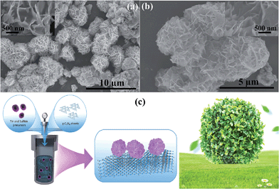
The morphology of the 3D flower-like SnS2 anchored on the g-C3N4 sheet surface was initially examined by SEM. The results revealed 3D flower-like SnS2 with a flake morphology and a 3–5 μm mean diameter on the surface of the sheets (Fig. 1a and b). On the other hand, the flower like structure contained a large number of randomly oriented intercrossed flakes with a nm range thickness (inset of Fig. 1a and b). SEM clearly showed that the g-surface of the g-C3N4 sheet is fully covered by SnS2 with well-arranged flakes with a 3D architecture. In addition, SEM also showed that the g-C3N4 sheet would also become entangled with the flower-like SnS2, which might be due to flake and flower formation during the crystallization stage. The formation of this type of architecture can be attributed to the synthesis process and it is believed that acetic acid, ethanol and thioacetamide play an important role as a solvent, catalyst for the hydrothermal reaction, enhancing the solubility, and as a source of sulfur. Fig. 1c presents the growth of the 3D flower-like SnS2 architecture on g-C3N4via a solvothermal process. First, the tin anion interacts with the acetic acid and forms a complex. Subsequently, thioacetamide was added to the reaction system, which was further decomposed and formed H2S, which will occur faster at increasing temperatures. The H2S reacted further with Sn ions to form SnS2, which is also in accordance with previous work. With increasing temperature, it was assumed that initially, SnS2 nanosheets and SnS2 tiny crystal seeds formed gradually and during the growth process, these sheets and tiny crystals tended to self-assemble and aggregate, and finally a 3D flower-like structure of SnS2 was formed. On the other hand, various processes, such as nucleation, growth aggregation, self-assembly, and Ostwald ripening, may be involved in the formation of a 3D flower-like architecture of SnS2. Nevertheless, the precise mechanism behind this type of architecture is unclear and a further detailed investigation is required. These types of 3D assembly structures have been reported.20–29TEM
The morphology and microstructure of the selective heterostructure were inspected closely by TEM and HR-TEM. Fig. 2 shows flower like SnS2 well grown on the surface of the g-C3N4. Fig. 2a and b clearly show the two-dimensional, sheet-like structure with a smooth surface of g-C3N4 present in the heterostructure. A closer inspection of the top view of SnS2 by HR-TEM revealed the well-ordered lattice structure of the SnS2, which is well matched with the reported data (Fig. 2d and e). EDX was conducted to examine the elemental distribution in the heterostructure, which revealed the presence of C, N, S, and Sn in the SnS2-g-C3N4-St heterostructure (Fig. 2f). Fig. 2g and h show scanning transmission electron microscopy elemental mapping images of the selective heterostructure, showing the presence of N, C, S, and Sn, which provides evidence for the existence of SnS2 and g-C3N4 in the heterostructure. Interestingly, the mapping images of S and Sn clearly show the distribution of C and N, which provides clear evidence of the presence or combination of SnS2 on or with the g-C3N4 sheets. These results further show that the 3D flower-like SnS2 is grown horizontally on the surface of the g-C3N4 sheet and can provide a heterojunction interface between SnS2 and g-C3N4.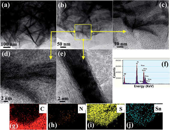 | ||
| Fig. 2 (a–e) TEM and HR-TEM images at different magnifications, (f) EDX, and (g–j) scanning transmission electron microscopy elemental mapping of the well-designed SnS2-g-C3N4-St heterostructure. | ||
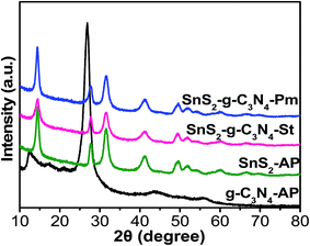
The phase structures of the g-C3N4-AP, SnS2-AP, SnS2-g-C3N4-St, and SnS2-g-C3N4-Pm heterostructures were determined by XRD, as shown in Fig. 3. The XRD pattern of g-C3N4-AP displayed distinct diffraction peaks at 13.06° 2θ and 27.47° 2θ, which were assigned to the interplanar stacking of aromatic units and the crystal plane of the graphitic material, respectively, clearly matching with previously reported work.3,13,14 Similarly, SnS2-AP showed diffraction peaks at 14.38°, 27.67°, 31.5°, 42.7°, and 49.47° 2θ, which are the standard peak positions of SnS2 with a hexagonal crystal structure (JCPDPS 22-0951).30 The XRD patterns of the SnS2-g-C3N4-St and SnS2-g-C3N4-Pm heterostructure did not show any new phase in the XRD pattern, indicating the purity of the samples but the peaks for g-C3N4-AP at 27.47° 2θ and for SnS2-AP at 28.4° 2θ were superimposed with each other, which is why the peak located at 27.47° 2θ becomes broader in the case of heterostructures. In addition, a close inspection of the comparative diffraction pattern of the SnS2-AP, SnS2-g-C3N4-St, and SnS2-g-C3N4-Pm heterostructure shows that the peak at 14.4° 2θ in the case of the SnS2-g-C3N4-St heterostructure was broader than that for the SnS2-g-C3N4-Pm heterostructure indicating that SnS2 was grown successfully on the g-C3N4 with a proper interaction through a solvothermal treatment.
UV-vis diffuse absorbance spectroscopy was used to examine the photo-physical characteristics, i.e. light absorption sensitivity and mobility band gaps of the g-C3N4-AP, SnS2-AP, SnS2-g-C3N4-St, and SnS2-g-C3N4-Pm heterostructures, as presented in Fig. 4. As expected, the fundamental absorption edges of g-C3N4-AP and SnS2-AP were observed at ∼590 and ∼450 nm, respectively, which is consistent with previously reported studies,31,32 whereas the SnS2-g-C3N4-St heterostructure showed distinctly enhanced absorption in the visible region. Furthermore, compared to the SnS2-g-C3N4-Pm heterostructure, which was prepared by a different method to understand the importance of a well-designed heterostructure, the SnS2-g-C3N4-St heterostructure displayed substantially enhanced visible light absorption characteristics with a red shift in the absorption edge, which was not present in the case of the SnS2-g-C3N4-Pm heterostructure. The above different characteristics of the heterostructure provide some evidence of the interaction between g-C3N4 and SnS2, which occurred during the solvothermal treatment. After the initial light absorption assessment, the mobility band gaps of the g-C3N4-AP, SnS2-AP, SnS2-g-C3N4-St, and SnS2-g-C3N4-Pm heterostructures were also measured from the band gap energy plot, which are displayed in Fig. 4b. A mobility band gap of ∼2.7 eV was found for g-C3N4-AP, whereas ∼2.1 eV was found for SnS2-AP. Similarly, ∼2.15 eV was found for SnS2-g-C3N4-St, whereas ∼2.0 eV was found for the SnS2-g-C3N4-Hy heterostructure.31 This clearly shows that the band gap of the SnS2-g-C3N4-St heterostructure was lower than that of the SnS2-g-C3N4-Pm heterostructure. This may be due to the presence of strong interfacial interactions at the heterojunction, which could be favorable for reducing the recombination rate of photogenerated electron hole pairs, thereby enhancing the photocatalytic performance of the present heterostructure.
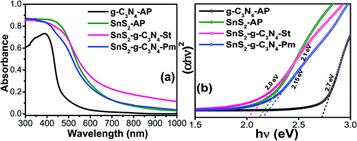 | ||
| Fig. 4 (a) UV-visible diffuse absorbance spectra and (b) estimated band gap energy plot of g-C3N4-AP, SnS2-AP, SnS2-g-C3N4-St, and SnS2-g-C3N4-Pm heterostructures. | ||
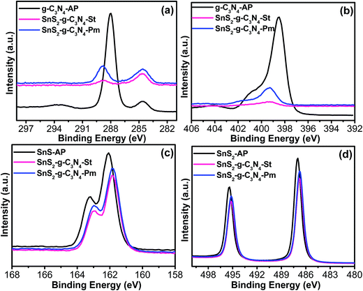
A surface-sensitive quantitative spectroscopic technique was used to examine the surface composition and chemical bonding configuration of the bare catalyst and heterostructure photocatalyst, as shown in Fig. 5. The C 1s spectra revealed two different photoelectron peaks present at a binding energy (BE) of 284.5 eV and 288.0 eV in the case of g-C3N4-AP, which depict the sp2 C–C bond of graphitic carbon and sp2 bonded carbon in the triazine rings, whereas these peaks in the case of SnS2-g-C3N4-St and SnS2-g-C3N4-Pm heterostructures shifted to a higher BE value, which could be evidence of the existence of interfacial interactions and bonding between the g-C3N4 and SnS2 (Fig. 5a). Similarly, the N 1s photoemission spectra exhibited a strong peak at BE 398.50 eV, corresponding to the presence of a triazine ring in the sample, which also shifted to a higher BE in the case of SnS2-g-C3N4-St, and SnS2-g-C3N4-Pm heterostructures (Fig. 5b). Interestingly, this shift was more prominent in the case of the SnS2-g-C3N4-Hy heterostructure, which means that strong interfacial interactions occurred during the solvothermal treatment. Furthermore, the S 2p (Fig. 5c) and Sn 3d (Fig. 5d) photoemission spectra were also analyzed to obtain greater insight into the bonding configuration and interfacial interaction between the two constituents. As shown in Fig. 4d, the peaks at 486.0 eV and 495.4 eV correspond to the spin–orbit doublets of Sn 3d5/2 and Sn 3d3/2, whereas Fig. 4c shows the S 2p photoemission spectra of SnS2-AP, SnS2-g-C3N4-St, and SnS2-g-C3N4-Pm heterostructures, indicating the presence of S–Sn bonding.32 Both S 2p and Sn 3d spectra show a shift of the BE to a lower side after the SnS2 loading on g-C3N4 sheets, which indicated the presence of a possible heterojunction interface in the form of Sn–N and S–C bonding. Zhang et al.33 and Liu et al.32 described in their metal sulfide-based heterostructures the formation of a heterojunction interface and interfacial interaction between nitrogen of the g-C3N4 and that metal species could easily alter the BE of the system due the formation of different types of bonds during the synthesis process. Overall, stronger electronic interaction/interfacial interactions are present in the SnS2-g-C3N4-St heterostructure, which might be helpful for improving the characteristics of the resulting heterostructure.
Visible light driven photocatalytic response
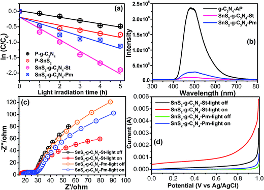
The above suggested heterojunction interface/interfacial interaction between the nitrogen pots of g-C3N4 and metal species and its significant effect on the catalytic activity of the resulting heterostructure were evaluated by the degradation of a model dye, rhodamine blue (RhB), which is used frequently in the photochemical and textile industries, under visible light illumination. The photolysis of the above pollutant was also tested and the results are presented in Fig. S1,† which shows almost negligible degradation capacity under visible light illumination. Fig. 6a shows the comparative degradation kinetic plots of the g-C3N4-AP, SnS2-AP, g-C3N4-SnS2-St, and SnS2-g-C3N4-Pm heterostructures as a function of visible light illumination. g-C3N4-AP and SnS2-AP showed poor photocatalytic activity owing to the fast charge recombination of the photoinduced charge carriers. On the other hand, compared to the bare constituent (g-C3N4-AP, SnS2-AP), the g-C3N4-SnS2-St and SnS2-g-C3N4-Pm heterostructures showed remarkably enhanced photocatalytic activity under similar experimental conditions. In particular, the SnS2-g-C3N4-St heterostructure exhibited excellent photocatalytic performance among all the photocatalysts (g-C3N4-AP, SnS2-AP, g-C3N4-SnS2-St, and SnS2-g-C3N4-Pm heterostructures). The apparent degradation rate constant (k) was also calculated to know the precise enhancement in the photocatalytic activity.18 The obtained k values of the g-C3N4-AP, SnS2-AP, g-C3N4-SnS2-St, and SnS2-g-C3N4-Pm heterostructures were ∼0.1063/h, ∼0.1313/h, ∼0.3690/h, and ∼0.2030/h, respectively. The SnS2-g-C3N4-St exhibited ∼3.5, ∼2.8, and ∼1.8-fold higher degradation performance than g-C3N4-AP, SnS2-AP, and SnS2-g-C3N4-Pm heterostructures, respectively. This enhanced performance of the SnS2-g-C3N4-St heterostructure showed that the design of the heterostructure using a solvothermal treatment could produce a unique heterojunction between the g-C3N4 and SnS2, which plays an important role in increasing the separation efficiency of the photogenerated charge carriers during the photocatalytic reaction.PL spectroscopy was used to probe the separation and recombination efficiency of the photoinduced charge carriers, which plays a major role in enhancing the photocatalytic performance of the catalyst.34,35 The strong emission spectra obtained from the PL setup unambiguously reflect the fast separation efficiency of the photoinduced charge carriers, whereas the lower intensity reflects the slow recombination of photoinduced charge carriers, which results in an improvement in the photocatalytic performance of the catalyst. The PL spectra of the g-C3N4-AP revealed a strong emission peak; however, after anchoring the SnS2 on the g-C3N4-AP the surface, the peak intensity was totally quenched in the case of the SnS2-g-C3N4-St heterostructure, which revealed the significant inhibition of electron/hole recombination (Fig. 6b). In addition, the SnS2-g-C3N4-Pm heterostructure displayed slightly higher emission compared to the SnS2-g-C3N4-St heterostructure. Based on the above observations, well-designed heterostructure formation between g-C3N4 and SnS2 is helpful for retarding electron/hole recombination, which helps increase the catalytic activity of the photocatalyst. This result reveals an analogous trend to the photocatalytic and forward EIS results.
After the initial assessment of the charge separation efficiency through PL over the SnS2-g-C3N4-St and SnS2-g-C3N4-Pm photocatalysts, EIS was conducted in the dark and under visible light illumination to gain deeper insight into the charge separation efficiency and charge transport phenomenon at the electrode electrolyte interface.3,13,30,32Fig. 6c displays the Nyquist plots of the SnS2-g-C3N4-St and SnS2-g-C3N4-Pm photoelectrodes, which shows that the semicircular arc observed in the case of SnS2-g-C3N4-St is much smaller than that of the SnS2-g-C3N4-Pm photoelectrode under similar photo illumination conditions. The observed smaller semicircular arc clearly indicated the smaller charge transfer resistance over the SnS2-g-C3N4-St photoelectrode. This enhances the effective separation of the photogenerated electron–holes, which is feasible for improving the photocatalytic activity of the SnS2-g-C3N4-St photocatalyst. This effective separation over the SnS2-g-C3N4-St might be due to the presence of SnS2 and formation of a good heterojunction during the hydrothermal treatment, which serve as photogenerated charge carrier capture centers or sinks, and also enhance the charge transfer capability. The smaller semicircular arc in the Nyquist plot demonstrates a lower electron transfer resistance value, effective separation, and easy transportation of the photogenerated electron–hole pairs. These results are also in accordance with the above photocatalytic results, as shown in Fig. 6b, and reveal an analogous trend to PL analysis and the photocatalytic activity.
The current voltage measurements of the SnS2-g-C3N4-St and SnS2-g-C3N4-Pm photoelectrode were also performed in the dark and under visible light illumination using half-cell measurements. As expected, the SnS2-g-C3N4-St photoelectrode under visible light illumination exhibited the highest photoelectrochemical response compared to the SnS2-g-C3N4-Pm photoelectrode under similar experimental conditions (Fig. 6d). This improvement in the photoelectrochemical performance of the SnS2-g-C3N4-Hy photoelectrode is proof of the effective separation of the photogenerated electrons–holes under visible light illumination, which originated from heterojunction formation with a good interfacial interaction and the presence of SnS2. The current–voltage, EIS, and PL results revealed an analogous trend to the visible light catalytic activity.
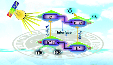
Based on the enhanced visible light photocatalytic performance and with the help of the photo-physical characteristics of the SnS2-g-C3N4-St heterostructure, the expected and tentative photoinduced charge separation and migration process mechanism over the SnS2-g-C3N4-St heterostructure is proposed (Fig. 7). The comparative results show that the SnS2-g-C3N4-St heterostructure exhibited the highest photocatalytic performance, whereas the bare counterpart exhibited very poor photocatalytic activity, even though both (g-C3N4-AP and SnS2-AP) had a narrow band gap. The enhanced performance of the rationally designed SnS2-g-C3N4-St heterostructure can be described by considering a few aspects, as follows.
The capacitive behavior and good charge collection properties of SnS2 in the heterostructure enable charge storage properties, which may facilitate charge separation and enhance the photocatalytic activity of the heterostructure. The separated charge carrier over the SnS2-g-C3N4-St heterostructure drove a series of oxidative and reductive reactions to produce superoxide radical anions (˙O2−) and hydroxyl radicals (HO˙), which play a decisive role in degrading the organic pollutant moiety.
The efficient interfacial interactions formed between g-C3N4 and SnS2 through a solvothermal treatment also facilitated the separation and migration of photoinduced electron holes, which triggered the ˙O2− and HO˙ and significantly improved the photocatalytic activity of the SnS2-g-C3N4-St heterostructure under visible light illumination.
The valence band (VB) and conduction band (CB) edge potential positions were calculated using the equation, and the mobility band gap was obtained from the UV-visible absorption spectra to obtain more information about the charge transfer process through the interface because the flow of photogenerated electrons and holes provides more evidence of an enhancement of the photocatalytic activity over the catalytic surface under visible light irradiation.32
| EVB = X − Ee + 0.5Eg |
| ECB = EVB − Eg |
Both g-C3N4 and SnS2 are excited and generate excess electrons and holes under visible light illumination due to their narrow band gap. The CB electron of g-C3N4 would migrate to the CB of SnS2, whereas the VB photogenerated holes of the SnS2 can migrate to the VB of the g-C3N4 through the heterojunction due to the abovementioned band-edge potential position difference. These simultaneous migrations of photogenerated electrons and holes through the heterojunction interfaces promote the collection of photogenerated electrons in the CB of SnS2 and photogenerated holes in the VB of g-C3N4. Therefore, the probability of recombination of photogenerated charge carriers is reduced. These separated photoinduced charge carriers could facilitate various types of oxidative and reductive reactions over the surface of the photocatalyst for the degradation of the pollutant under visible light illumination. The major reaction that occurred over the SnS2-g-C3N4-St heterostructure during the photocatalytic process was the formation of superoxide radical anions (˙O2−) and hydroxyl radicals (HO˙), which are responsible for the photodegradation and mineralization of pollutants, which can be explained by the following reactions steps:
| g-C3N4 + hν → g-C3N4 (e− + h+) |
| SnS2 + hν → SnS2 (e− + h+) |
| g-C3N4 (e−) + SnS2 → g-C3N4 + SnS2 (e−) |
| SnS2 (e−) + O2 → SnS2 + ˙O2− |
| ˙O2− + H2O → OH˙ |
| g-C3N4 (h+) + H2O → g-C3N4 + H+ + ˙OH |
| g-C3N4 (h+) + OH− → g-C3N4 + ˙OH |
| ˙OH + RhB → degradation products |
In addition to the above characteristics of the photocatalyst, the specific surface areas of the g-C3N4-AP and SnS2-g-C3N4-St heterostructure were also measured to elucidate the available surface area, which facilitate sufficient contact between the pollutant or dyes. The BET specific surface area of g-C3N4-AP and SnS2-g-C3N4-St heterostructure was 6.40 m2 g−1 and 23.17 m2 g−1, respectively. The SnS2-g-C3N4-St heterostructure exhibited a 3.7 times higher surface area than the g-C3N4-AP. This enhanced surface area clearly supports the photocatalytic activity of the resulting heterostructure.
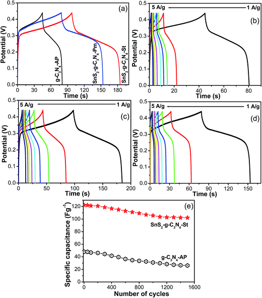
The half-cell electrochemical supercapacitive performance of the designed SnS2-g-C3N4 heterostructure was assessed from the galvanostatic charge–discharge measured at different current loads and the specific capacitance was calculated using the reported formula.36,37Fig. 8 presents the comparative GCD curves of g-C3N4-AP, SnS2-AP, SnS2-g-C3N4-St, and SnS2-g-C3N4-Pm heterostructures, which shows that the SnS2-g-C3N4-St exhibited enhanced electrochemical performance with a high capacitance, whereas g-C3N4-AP, SnS2-AP, and SnS2-g-C3N4-Pm showed poor electrochemical performance at a similar current, which further highlights the combined effects of g-C3N4 and SnS2 in the heterostructure. The discharge specific capacitances of g-C3N4-AP were 106.06, 113.37, 48.48, 43.60, 40.32, 37.03, 29.39, and 26.74 F g−1 at a current density of 1, 1.5, 2, 2.5, 3, 3.5, 4, and 5 A g−1, respectively whereas 178.83, 113.58, 86.55, 71.80, 64.53, 56.53, 52.18, and 52.98 F g−1 were obtained for the SnS2-g-C3N4-Pm heterostructure at similar current loads. Similarly, for the SnS2-g-C3N4-St heterostructure at similar current loads, the specific capacitance was 210.30, 146.40, 122.41, 110.63, 102.34, 96.86, 94.88, and 93.13 F g−1. The abovementioned results clearly show that the SnS2-g-C3N4-St heterostructure has excellent electrochemical capacitance performance compared to the g-C3N4-AP and SnS2-g-C3N4-Pm heterostructures even at lower and higher currents. Obviously, the capacitance was high at a low current load because the electrolyte ions have more time to access and diffuse into the pores of the electrode. These capacitance values were compared with those of g-C3N4 because g-C3N4 is the main matrix and was used as a surface to grow the flower like SnS2. Therefore, it was compared with only g-C3N4. Although the electrochemical supercapacitance performance was not very high compared to the carbon-based electrode materials and was unsatisfactory, this will open a window for further research to improve the performance in terms of the specific capacitance and stability of the present heterostructure.
The galvanostatic charge and galvanostatic discharge experiments of the SnS2-g-C3N4-St heterostructure were performed repeatedly over the potential range of 0–0.4 V and at a current load of 2 A g−1 for more than 1500 cycles to assess its potential for application as a long term stable superlative electrode material. As shown in Fig. 8e, the SnS2-g-C3N4-St heterostructure electrode displayed a decrease in specific capacitance with increasing number of cycles and maintained 84% capacitance from its initial value after 1500 cycles. On the other hand, the electrode prepared from the other materials exhibited a high decay rate of the specific capacitance from its initial value. This improved stability of the SnS2-g-C3N4-St heterostructure electrode could be due to the 3D architecture and interconnected heterostructures between the g-C3N4 sheet and SnS2.
The improved half-cell electrochemical performance of the resulting heterostructure could be attributed to the nitrogen-rich framework with the layered characteristics of g-C3N4 and the 3D architecture of SnS2 with a hierarchical architecture.36,37 The nitrogen framework accelerates the charge transformation whereas the layered structure of g-C3N4 decreases the interlayer resistance and enhances the kinetics on the electrode surface. The hierarchical architecture of the SnS2 enables more exposed surfaces and channels, which fully utilized the electrolytic solution and was helpful in reducing the path length for the rapid diffusion of charge carriers during the electrochemical experiment.36,37
Conclusion
Novel 3D flower-like narrow band SnS2 was grown successfully on a narrow band g-C3N4 sheet by a simple solvothermal process, and its visible light sensitivity towards the photocatalytic degradation of organic pollutants and photocurrent generation was examined. The resulting heterostructure was also used for the first time as an electrochemical supercapacitive material in a half-cell electrochemical assembly setup. The well-designed SnS2-g-C3N4-St heterostructure showed significantly enhanced electrochemical supercapacitive performance and visible light responsive photocatalytic activity compared to the bare materials and similar composite materials synthesized using a different method. The better visible light sensitive performance was attributed to the suitable band gap and interfacial interactions, which are helpful for facilitating charge transfer through the heterojunction, retarding the recombination rate of photoinduced electrons and holes, and lengthening the lifetime of the photoinduced charge carriers. These phenomena were observed clearly by EIS, PL and XPS. In contrast, the improved capacitance performance was attributed to the unique architecture with a high surface area, capacitive behavior, and layered features with a nitrogen content that increases the conductivity and provides active sites to the electrode. The high visible light responsive performance and improved electrochemical supercapacitance behavior of the SnS2-g-C3N4-St heterostructure could make it a suitable architecture for practical applications in pollutant degradation and as an energy storage electrode material.Acknowledgements
This study was supported by the Priority Research Centers Program (Grant No. 2014R1A6A1031189), and by the Basic Science Research Program (Grant No. 2015R1D1A3A03018029) through the National Research Foundation of Korea (NRF) funded by the Ministry of Education.References
- J. Liu, H. Wang and M. Antonietti, Chem. Soc. Rev., 2016, 45, 2308–2326 RSC.
- W. Ong, L. Tan, Y. Ng, S. Yong and S. Chai, Chem. Rev., 2016, 116(12), 7159–7329 CrossRef CAS PubMed.
- Y. Zhang, Q. Zhang and Q. Shi, Sep. Purif. Technol., 2015, 142, 251–257 CrossRef CAS.
- G. Wu, Y. Hu, Y. Liu, J. Zhao, X. Chen, V. Whoehling, C. Plesse, G. T. M. Nguyen, F. Vidal and W. Chen, Nat. Commun., 2015, 6, 7258 CrossRef CAS PubMed.
- L. Shi, J. Zhang, H. Liu, M. Que, X. Cai, S. Tan and L. Huang, Mater. Lett., 2015, 145, 150–153 CrossRef CAS.
- X. Chen, X. Zhu, Y. Xiao and X. Yang, J. Electroanal. Chem., 2015, 743, 99–104 CrossRef CAS.
- Q. Chen, Y. Zhao, X. Huang, N. Chen and L. Qu, J. Mater. Chem. A, 2015, 3, 6761–6766 CAS.
- C. Liu, Y. Zhang, F. Dong, A. H. Reshak, L. Ye, N. Pinna, C. Zeng, T. Zhang and H. Huang, Appl. Catal., B, 2017, 203, 465–474 CrossRef CAS.
- N. Tian, H. Huang, C. Liu, F. Dong, T. Zhang, X. Du, S. Yua and Y. Zhang, J. Mater. Chem. A, 2015, 3, 17120–17129 CAS.
- S. A. Ansari and M. H. Cho, Sci. Rep., 2016, 6, 25405 CrossRef CAS PubMed.
- C. Liu, H. Huang, X. Du, T. Zhang, N. Tian, Y. Guo and Y. Zhang, J. Phys. Chem. C, 2015, 119, 17156–17165 CAS.
- C. Liu, Y. Zhang, F. Dong, X. Du and H. Huang, J. Phys. Chem. C, 2016, 120, 10381–10389 CAS.
- S. A. Ansari, M. O. Ansari and M. H. Cho, Sci. Rep., 2016, 6, 27713 CrossRef CAS PubMed.
- K. Zhu, W. Wang, A. Meng, M. Zhao, J. Wang, M. Zhao, D. Zhang, Y. Jia, C. Xu and Z. Li, RSC Adv., 2015, 5, 56239–56243 RSC.
- M. Tahir, C. Cao, N. Mahmood, F. K. Butt, A. Mahmood, F. Idrees, S. Hussain, M. Tanveer, Z. Ali and I. Aslam, ACS Appl. Mater. Interfaces, 2014, 6, 1258–1265 CAS.
- S. Vadivel, D. Maruthamani, A. Habibi-Yangjeh, B. Paul, S. S. Dhar and K. Selvam, J. Colloid Interface Sci., 2016, 480, 126–136 CrossRef CAS PubMed.
- S. A. Ansari, M. S. Ansari and M. H. Cho, Phys. Chem. Chem. Phys., 2016, 18, 3921–3928 RSC.
- Z. Khan, T. R. Chetia and M. Qureshi, Nanoscale, 2012, 4, 3543–3550 RSC.
- A. Umar, M. S. Akhtar, G. N. Dar, M. Abaker, A. Al-Hajry and S. Baskoutas, Talanta, 2013, 114, 183–190 CrossRef CAS PubMed.
- Z. Wu, Y. Xue, Y. Zhang, J. Li and T. Chen, RSC Adv., 2015, 5, 24640–24648 RSC.
- Y. C. Zhang, J. Li, M. Zhang and D. D. Dionysiou, Environ. Sci. Technol., 2011, 45, 9324–9331 CrossRef CAS PubMed.
- Y. C. Zhang, Z. N. Du, S. Y. Li and M. Zhang, Appl. Catal., B, 2010, 95, 153–159 CrossRef CAS.
- Y. Sun, G. Li, J. Xu and Z. Sun, Mater. Lett., 2016, 174, 238–241 CrossRef CAS.
- X. Zhang, X. Ge and C. Wang, Cryst. Growth Des., 2009, 9(10), 4302–4307 Search PubMed.
- Y. C. Zhang, Z. N. Du, K. W. Li and M. Zhang, Sep. Purif. Technol., 2011, 81, 101–107 CrossRef CAS.
- Y. Lei, S. Song, W. Fan, Y. Xing and H. Zhang, J. Phys. Chem. C, 2009, 113, 1280–1285 CAS.
- J. Gong, S. Yu, H. Qian, L. Luo and X. Liu, Chem. Mater., 2006, 18(8), 2012–2015 CrossRef CAS.
- T. S. Natarajan, H. C. Bajaj and R. J. Tayade, CrystEngComm, 2015, 17, 1037–1049 RSC.
- H. Ke, W. Luo, G. Cheng, X. Tian and Z. Pi, Micro Nano Lett., 2009, 4(3), 177–180 CAS.
- M. Sun, Q. Yan, T. Yan, M. Li, D. Wei, Z. Wang, Q. Wei and B. Du, RSC Adv., 2014, 4, 31019–31027 RSC.
- Y. C. Zhang, Z. N. Du, K. W. Li, M. Zhang and D. D. Dionysiou, ACS Appl. Mater. Interfaces, 2011, 3(5), 1528–1537 CAS.
- Y. Liu, P. Chen, Y. Chen, H. Lu, J. Wang, Z. Yang, Z. Lu, M. Lia and L. Fang, RSC Adv., 2016, 6, 10802–10809 RSC.
- Z. Zhang, J. Huang, M. Zhang, Q. Yuan and B. Dong, Appl. Catal., B, 2015, 163, 298–305 CrossRef CAS.
- F. Wang, W. Li, S. Gu, H. Li, X. Liu and M. Wang, ACS Sustainable Chem. Eng., 2016, 4(12), 6288–6298 CrossRef CAS.
- F. Zhang, X. Li, Q. Zhao and D. Zhang, ACS Sustainable Chem. Eng., 2016, 4(9), 4554–4562 CrossRef CAS.
- L. Wang, Y. Ma, M. Yang and Y. Qi, RSC Adv., 2015, 5, 89069–89075 RSC.
- L. Ma, L. Xu, X. Zhou, X. Xu and L. Zhang, RSC Adv., 2015, 5, 105862–105868 RSC.
Footnote |
| † Electronic supplementary information (ESI) available. See DOI: 10.1039/c6se00049e |
| This journal is © The Royal Society of Chemistry 2017 |

