 Open Access Article
New perspective to understand the effect of electrochemical prelithiation behaviors on silicon monoxide†
Chengxu Shenab,
Rusheng Fua,
Yonggao Xia *a and
Zhaoping Liu
 *a
*a
aAdvanced Li-ion Battery Engineering Laboratory, Key Laboratory of Graphene Technologies and Applications of Zhejiang Province, Ningbo Institute of Materials Technology and Engineering, Chinese Academy of Sciences, Ningbo 315201, P. R. China. E-mail: xiayg@nimte.ac.cn; liuzp@nimte.ac.cn; Fax: +86-574-8668-5096; Tel: +86-574-8668-5096
bUniversity of Science and Technology of China, Nanoscience and Technology Institution, Suzhou 215123, P. R. China
First published on 18th April 2018
Abstract
Electrochemical prelithiation is a facile, effective and extensively used method to improve the initial coulombic efficiency of SiO. However, much less research attention has been devoted to prelithiation effect on initial several cycles. Here, we introduce a new perspective to evaluate the prelithiation behaviors, which could understand in depth the electrochemical prelithiation behaviors and their effects on the following two cycles. Then X-ray photoelectron spectroscopy was further performed to pinpoint the reaction products. It has been found that the quantity of irreversible Li4SiO4, Li2O and SEI (Li2CO3 and LiF) and reversible LixSi are increasing as the prelithiation time extending. When the prelithiation time extending over 20 min, only alloy reaction of Si has been revealed. The regeneration of SEI discloses at least 7% capacity loss in the first cycle which depends on the prelithiated time. However, the reformation of SEI in the second cycles reveals 3% capacity loss. Because the coulombic efficiencies are independent on prelithiated time in the second cycle which indicates only one discharge/charge cycle is enough to form integrated SEI and adequate irreversible Li4SiO4 and Li2O except part of unreactive SiOx.
Introduction
Today, lithium-ion batteries (LIBs) have made significant progress in consumer electronics, and exhibit great potential for electrical vehicles and grid-scale energy storage.1,2 Silicon, meeting the growing demand for high-energy LIBs, is regarded as one of the most promising anodes for the next-generation lithium ion battery.3–5 Unfortunately, its poor cycle performance, mainly caused by extremely large Si volume changes (>300%) during discharging/charging, limited the application at a commercial scale.6–8 As an alternative approach to alleviate the drawback, SiOx, due to their relatively low volume expansion (<200%) and few side reactions with electrolyte which give rise to high capacity retention during electrochemical cycling, have captured the interest of the industry.9–11 Nevertheless, the introduced oxygen in SiOx can produce awful irreversible products such as Li2O and lithium silicate during the initial several lithiation processes, which results in large irreversible capacity and low initial coulombic efficiency (ICE).11,12 Furthermore, the formation of solid electrolyte interphase (SEI) on the surface of anodes during the first cycle causes a high irreversible capacity loss and results in low ICE value.13 Low ICE value prevents high specific capacity anodes from being viable when paired with cathodes in a full cell.14The previous studies shown that silicon monoxide (SiO) anode can be effectively prelithiated with lithium metal powder (SLMP) based on pressure-activation and shorting mechanism.15 Seong and his co-workers reported that lithium pre-doping method could increase ∼5% of ICE value because of pre-generated lithium silicate and lithium oxide, which were identified by X-ray diffractometer (XRD) patterns.15 Based on this research, the current studies have developed versatile prelithiation technologies for SiOx anodes, including using LixSi or stabilized SLMP as additive,16–18 electrochemical prelithiation19 and prelithiation through a self-discharge mechanism.20–22 Guo and his co-workers developed a solution-processed slot dye coating method to prelithium SiO anode and the ICE increased from 56.8% to 88.1% in SiO/NMC full cell.18 The study confirmed that a high-quality SEI layer that formed during SLMP prelithiation process is crucial. Not only SEI but also lithium silicates were generated during prelithiation which could be confirmed from the absence of cathodic peak ∼0.4 V in the differential capacity plots.22 Yom and his co-workers figured out that lithium silicate was generated when the mixture of SiO and Li powder suffers from a high-temperature solid state reaction process, which were determined by XRD and selected area electron diffraction (SAED).23 Consequently, the prelithiated SiO exhibited higher ICE about 82.1% compared with 58.5% of pristine SiO. In addition to SEI and irreversible by-products, Li–Si alloy formed after prelithiated Si was readily demonstrated by transmission electron microscopy (TEM), scanning electron microscopy (SEM) and XRD.19,24 Analogically, the ICE would be increased from 73.6% to 94.9% via a circuit short with Li metal foil and carbon coated SiOx in the presence of an optimized external resistance. As the shorting time increasing, the progressive reactions between Li and SiOx would form Li–Si alloy.19 As all mentioned above, SEI and irreversible components (lithium silicate and Li2O) contribute to the low coulombic efficiency, whereas, Li–Si alloy as reversible component contributes to the reversible capacity. When it comes to SiOx, researchers stress the importance of electrochemical performances, especially initial coulombic efficiency, but much less research attention has been devoted to prelithiation behaviors and their effects on the following several cycles when trying to exploit all kinds of prelithiation approaches.
In this work, in order to understand the electrochemical behaviours of SiO after prelithiation operation more clearly, we strive to research the mechanisms of prelithiation using electrochemical characterizations, SEM, X-ray photoelectron spectroscopy (XPS) and high-resolution transmission electron microscopy (HR-TEM). Self-discharge prelithiation method was selected in this study. The prelithiated electrode subjects to charge (extract Li+) first and followed by discharge/charge cycles which was used for special consideration.
Experimental
Electrode preparation and prelithiation
We employ commercial micro-SiO (D50 ≈ 5 μm, Fig. S1 and S2†) without any treatment as the pristine materials. The electrodes were prepared by coating slurries containing the SiO (80 wt%) as active materials, conducting agent (Super-P 10 wt%), and sodium carboxymethyl cellulose (CMC, 10 wt%) dissolved in deionized water on Cu foil. After coating, the electrode was dried at 80 °C for 6 h and then pressed under a pressure of 6 MPa. Circular electrodes (13 mm in diameter) were punched out and dried under vacuum at 120 °C for 8 h after weighing, SiO mass loading is ∼1.4 mg cm−2. The electrode was put on the gasket and then 0.2 mL of electrolyte was dropped on the electrode. Prior to 150 g weight was added, Li metal foil was located on top of the electrode. After a specific time of prelithiation, the electrode was peeled from the Li foil carefully and washed three times with dimethyl carbonate (DMC) to remove the residual electrolyte and lithium salts.Electrode characterizations
Composition analysis for the electrodes were performed with X-ray photoelectron spectroscopy (XPS). Data treatment was performed with Casa XPS software. The treated electrodes were transferred from glovebox to the XPS apparatus using a specific transfer vessel to avoid exposing to air. All spectra were calibrated using C (sp2) binding energy of 284.6 eV as a reference. The morphology of the electrodes were conducted using scanning electron microscope (SEM).Electrochemical measurements
The coin cells CR2032 were assembled using Li foil as a counter electrode within Ar-filled glove box (H2O level < 0.1 ppm and O2 level < 0.1 ppm). Celgard 2400 was used as separator, with 1 M LiPF6 as commercial electrolyte in EC/DEC = 1![[thin space (1/6-em)]](https://www.rsc.org/images/entities/char_2009.gif) :
:![[thin space (1/6-em)]](https://www.rsc.org/images/entities/char_2009.gif) 1 by volume with 5 wt% FEC. The galvanostatic cycling was performed using Land CT 2100A battery-test system. The half-cells were discharged (Li+ insertion) and charged (Li+ extraction) in the potential range between 0.005 and 1.5 V under specific current densities. The capacity was calculated on the basis of active materials. Cyclic voltammetry (CV) curves were recorded by Solartron using CR2032-type coin cells with scanning rate of 0.1 mV s−1 and voltage window at 0.005–2.0 V.
1 by volume with 5 wt% FEC. The galvanostatic cycling was performed using Land CT 2100A battery-test system. The half-cells were discharged (Li+ insertion) and charged (Li+ extraction) in the potential range between 0.005 and 1.5 V under specific current densities. The capacity was calculated on the basis of active materials. Cyclic voltammetry (CV) curves were recorded by Solartron using CR2032-type coin cells with scanning rate of 0.1 mV s−1 and voltage window at 0.005–2.0 V.
Results and discussion
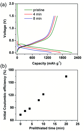
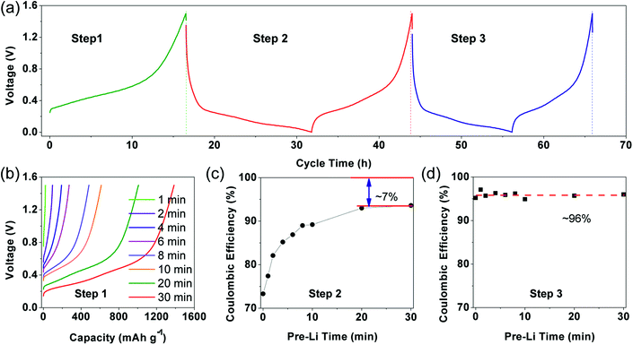
Generally, initial coulombic efficiency (ICE) was given impressive attention to evaluate the modification effect of the prelithiation operation. Pristine and prelithiated electrodes with different prelithiation time were first galvanostatically discharged to 0.005 V and then charged to 1.5 V. As shown in Fig. 1(a), the charge capacity of prelithiated electrodes is similar to the pristine electrode while the discharge capacity of prelithiated electrodes is lower than the pristine electrode. This is reasonable because the insertion of lithium compensates the lithium loss derived from the formation of irreversible by-products, but don't effects the content of reversible component. Furthermore, the ICEs are boosted with the increasing of prelithiation time shown in Fig. 1(b). Apparently, when the SiO electrodes were prelithiated more than 8 min, the ICEs would exceed 100%. Numerously ex situ characterizations revealed the previously accepted findings that preformation SEI, lithium silicates, Li2O and LixSi which account for the improved ICE. However, less research has separately discussed the effect of reversible and irreversible components generated during prelithiation process and paid attention to the effect of prelithiation treatment on the following two cycles except ICE. Herein, we introduce a different evaluation strategy to characterize the prelithiation behaviours, which could understand in depth the effect of electrochemical prelithiation behaviours on the electrode during the initial several cycles through a facile electrochemical data analysis.Electrochemical characterizations of prelithiated SiO electrode are shown in Fig. 2. To reveal the influence of irreversible components, Fig. 2(a) showed three successive steps what we applied to investigate the prelithiated electrodes. In step 1, the prelithiated electrode was firstly charged to 1.5 V at 0.05C (1C = 1500 mA h g−1) to extract the reversible lithium formed during the prelithiation process what we called them reversible capacity, and then galvanostatically discharge/charge at 0.05C in the following step 2 and step 3. In Fig. 2(b), the charging capacity of prelithiated electrode demonstrated the formation of reversible component such as LixSi. Higher specific capacity means more reversible components which are strongly depended with the prelithiation time.
For distinction with coulombic efficiency (CE) in the traditional galvanostatic processes, we introduced the definition of coulombic efficiency in step 2 (CE2) and coulombic efficiency in step 3 (CE3) corresponding to the red and blue lithiation–delithiation processes in Fig. 2(a), respectively. Specially, if the electrode didn't subject to prelithiate, the value of CE2 is equal to ICE (see in Fig. 2(c)). After 2 min prelithiation treatment, the CE2 remarkably enhanced from 73.3% to 82.1% while the reversible capacity is ∼96.5 mA h g−1 (96.5/1500 = 6.4%) (Fig. 1(b), (c) and S3†). It indicates that more irreversible components formed at the beginning of prelithiation process (82.1–73.3% = 8.8% > 6.4%) than reversible components. Moreover, the open circuit voltage (OCV) are rapidly decreased to 0.7 V which respected to the formation of SEI (Fig. S4†). We could be concluded that it would generate SEI, lithium silicates, Li2O and LixSi as long as the contact between Li metal and SiO anode. It can also be demonstrated by the cyclic voltammogram showed in Fig. S5.† The pristine electrode presents apparent reduction peak at about 0.7 V in the first cycle while it couldn't be observed both in the second cycle and the electrode treated with 2 min prelithiation. This demonstrates that the formation of SEI happened firstly during prelithiation process. Lithium silicates and Li2O could be identified by the following XPS analysis. When prelithiation time elapsed from 2 min to 20 min, in addition to the increasing reversible LixSi (Fig. S3†), the OCP of prelithiated electrodes decreased from 0.5 to 0.3 V, a very similar voltage range corresponding to the formation of irreversible component of Li2O and lithium silicates.25 Consequently, CE2 rapidly increased (Fig. 2(c)). It must be noted that the increase of CE2 indicated the increasing formation of irreversible components occurred at prelithiated process. When the prelithiation time extended to 20 min, the CE2 increases up to 93% and then the value keeps stable, which means 20 min is sufficient to form adequate SEI and maximum quantity of lithium silicate and Li2O. Hence, the regeneration of SEI in step 2 results in 7% irreversible capacity loss at least because of the pulverization of SiO particles. The discharge/charge curve about step 2 showed in Fig. S6† as the complementary information to demonstrate the formation of irreversible components during prelithiation. The discharge capacity of the pristine is 2095.4 mA h g−1 and the charge capacity is 1543.4 mA h g−1 with initial coulombic efficiency of 73.7%. So, the initial irreversible capacity loss is about 552 mA h g−1. When the electrode prelithiated for 2 min, it exhibits similar charge capacity of 1540.5 mA h g−1 and significantly enhanced coulombic efficiency of 82.1%. After 20 min prelithiation, the irreversible capacity is just 71 mA h g−1 with discharge capacity 1501.0 mA h g−1 and coulombic efficiency 93%. Then the coulombic efficiency is almost independent with extending prelithiation time. The huge decay of irreversible capacity loss can be attributed to the formation of more irreversible components (such as SEI, lithium silicate and Li2O) when the electrode is subjected to prelithium for more time.
The CE3 (coulombic efficiency in step 3) showed in Fig. 2(d) maintained at ∼96% (∼4% irreversible capacity) which may correspond to SEI regeneration in step 3. Stable CE3 value demonstrates that irreversible components (such SEI, lithium silicate and Li2O) have already formed sufficiently when suffer from prelithiation process and charge/discharge process at step 2, so that no irreversible components further formed at step 3 except little regenerated SEI.
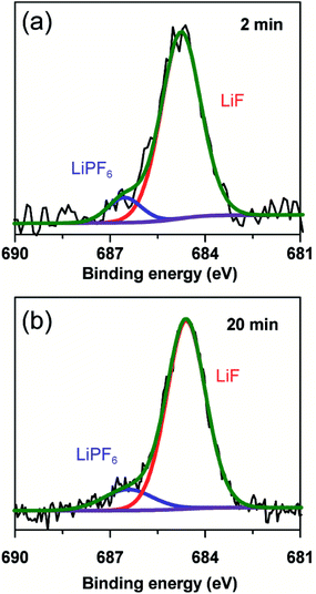
To further clarify the prelithiated products of the SiO anode, XPS was conducted to distinguish the prelithiated components combined with etching technology. As shown in Fig. 3, the pristine electrode and the electrodes subjected to 2 and 20 min prelithiation were labeled as pristine, 2 min and 20 min, respectively. When comparing the pristine electrodes before and after etching, they show the same O 1s spectra with the binding energy at ∼532.45 eV assigned to the CMC binder or SiOx (Fig. 3(a) and (b)).12 After prelithiation for 2 min, primary O 1s peak in Fig. 3(c) is attributed to Li2CO3 (531.7–532 eV) which could account for the formation of SEI.26 As well, weak O 1s peaks assigned to Li4SiO4 (530.7–531.3 eV) and Li2O (∼528.7 eV) demonstrate that lithium has reacted with SiO which is more clearly when most of the SEI was etched in Fig. 3(d).12,27 When extending the prelithiated time to 20 min, only SEI species are detected in Fig. 3(e) because of thick SEI covering layer. Numerous irreversible components Li4SiO4 and Li2O are shown in Fig. 3(f) when peeling off the cover layer. Meanwhile, the existing of SiOx indicate only a part of SiOx could be reacted with lithium due to the sluggish kinetics which hampered the further reaction. Furthermore, irreversible by-product Li4SiO4 was confirmed by comparing analysis with the prelithiated electrode and the delithiated electrode shown in Fig. S7.† Fig. 4 shows the Li 1s spectra of SiO electrode after prelithiation for 2 and 20 min, and their difference before and after sputtering. In addition to the irreversible products Li4SiO4 (∼55.3 eV) and Li2O (∼56.2 eV), reversible products LixSi (∼54.5 eV) are apparently generated after prelithiation for 2 min which could be detected after etching SEI layer. When the prelithiation time up to 20 min, distinct LixSi signals would be exhibited before etching (Fig. 4(c)). Though the binging energy of Li2O and LiF are difficult to separate by Li 1s spectra, F 1s gives significant LiF signals (∼684.6 eV) with respect to the SEI component (Fig. 5).28 Another deconvolution peak of F 1s (∼686.6 eV) is attributed to the residual LiPF6 which was not washed by DMC solvent.
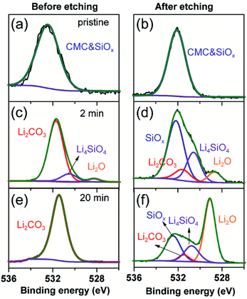 | ||
| Fig. 3 O 1s spectra of the pristine electrode, 2 min prelithiated electrode and 20 min prelithiated electrode. (a, c and e) before etching and (b, d and f) after etching. | ||
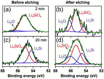 | ||
| Fig. 4 Li 1s spectra of 2 min prelithiated electrode and 20 min prelithiated electrode. (a and c) Before etching, (b and d) after etching. | ||
Subsequently, SEI could be directly confirmed by scanning electron microscopy (SEM) characterization. Fig. 6 shows the electrode morphologies of pristine, prelithiated for 2 min and undergone one cycle. The surface of prelithiated electrode is similar to the electrode subjected one cycle which is different to the pristine one because of the coverage of SEI. These results are well agree with the conclusions made by XPS analysis.
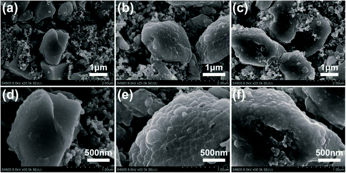 | ||
| Fig. 6 SEM images of the pristine electrode (a and d), after 2 min prelithiated electrode (b and e), and pristine electrode suffering from the first cycle (c and f). | ||
According to the abovementioned analysis, the prelithiation reaction of SiO, therefore, might be suggested as following:
| SiO + 2Li+ + 2e− → Li2O + Si | (1) |
| 4SiO + 4Li+ + 4e− → Li4SiO4 + 4Si | (2) |
| Si + xLi+ + xe− ↔ LixSi | (3) |
Firstly, SiO is reduced to Si during prelithiation, as expressed in eqn (1) and (2), followed by the further generation of Li–Si alloy, as described in eqn (3). The irreversible formation of Li2O and Li4SiO4 during prelithiation could reduce the irreversible capacity loss in the initial cycle. After prelithiation for 2 min, Li2O can be detected on the surface due to thin SEI layer. When the prelithiation time extended to 20 min, remarkable Li2O could be only detected in depths rather than the surface of electrode, which may attribute to coverage effect of thick SEI. LixSi, which contributes the high reversible capacity, could be also formed by the electrochemical prelithiation processes.
Conclusions
In this work, we introduce a different evaluation strategy to understand the effect of prelithiation operation on the electrochemical behaviors of SiO anode. At the beginning of prelithiation process, Li4SiO4, Li2O and SEI (including Li2CO3 and LiF) are dominantly generated combined with reversible LixSi alloy. After further prelithiation, the thickness of SEI increased, but its components have not changed significantly except increasing amount of LixSi. When the prelithiation time extending over 20 min, the irreversible components such as SEI, lithium silicate and Li2O are formed sufficiently but a part of SiOx is left as inactive material. Subsequent reaction is dominated by the formation of LixSi, Si reacted with Li metal. The capacity loss is at least 7% during the first cycle after prelithiation which need to be consumed for the regeneration of SEI. After electrochemical prelithiation treatment, only one discharge/charge cycle is enough to form integrated SEI and irreversible Li4SiO4 and Li2O are sufficiently generated because the coulombic efficiencies are independent on prelithiated time in the second cycle. In addition to SEI formation during the prelithiation step and regeneration after the following one cycle, the regeneration of SEI will reveal 3% capacity loss during the second cycle.Conflicts of interest
There are no conflicts to declare.Acknowledgements
This work was supported by the National Key R&D Program of China (Grant No. 2016YFB0100100), the National Natural Science Foundation of China (Grant No. 21371176), Strategic Priority Research Program of Chinese Academy of Sciences (CAS, Grant No. XDA09010101) and Key Research Program of Chinese Academy of Sciences (Grant No. KGZD-EW-T08).Notes and references
- J.-M. Tarascon and M. Armand, Nature, 2001, 414, 359–367 CrossRef CAS PubMed.
- G. Jeong, Y.-U. Kim, H. Kim, Y.-J. Kim and H.-J. Sohn, Energy Environ. Sci., 2011, 4, 1986 CAS.
- W. Luo, X. Chen, Y. Xia, M. Chen, L. Wang, Q. Wang, W. Li and J. Yang, Adv. Energy Mater., 2017, 7, 1701083 CrossRef.
- W. Zhang, J. Power Sources, 2011, 196, 13–24 CrossRef CAS.
- A. Casimir, H. Zhang, O. Ogoke, J. C. Amine, J. Lu and G. Wu, Nano Energy, 2016, 27, 359–376 CrossRef CAS.
- L. Y. Beaulieu, K. W. Eberman, R. L. Turner, L. J. Krause and J. R. Dahn, Electrochem. Solid-State Lett., 2001, 4, A137 CrossRef CAS.
- S. Chen, L. Shen, P. A. van Aken, J. Maier and Y. Yu, Adv. Mater., 2017, 29, 1605650 CrossRef PubMed.
- B. Wang, X. Li, X. Zhang, B. Luo, Y. Zhang and L. Zhi, Adv. Mater., 2013, 25, 3560–3565 CrossRef CAS PubMed.
- J.-W. Song, C. C. Nguyen and S.-W. Song, RSC Adv., 2012, 2, 2003 RSC.
- J.-I. Lee and S. Park, Nano Energy, 2013, 2, 146–152 CrossRef CAS.
- M. Ko, S. Chae, J. Ma, N. Kim, H.-W. Lee, Y. Cui and J. Cho, Nat. Energy, 2016, 1, 16113 CrossRef CAS.
- B. Philippe, R. Dedryvère, J. Allouche, F. Lindgren, M. Gorgoi, H. Rensmo, D. Gonbeau and K. Edström, Chem. Mater., 2012, 24, 1107–1115 CrossRef CAS.
- U. Kasavajjula, C. Wang and A. J. Appleby, J. Power Sources, 2007, 163, 1003–1039 CrossRef CAS.
- M. W. Forney, M. J. Ganter, J. W. Staub, R. D. Ridgley and B. J. Landi, Nano Lett., 2013, 13, 4158–4163 CrossRef CAS PubMed.
- W. Seong, K. T. Kim and W. Y. Yoon, J. Power Sources, 2009, 189, 511–514 CrossRef.
- J. Zhao, Z. Lu, N. Liu, H. W. Lee, M. T. McDowell and Y. Cui, Nat. Commun., 2014, 5, 5088 CrossRef CAS PubMed.
- J. Zhao, Z. Lu, H. Wang, W. Liu, H. W. Lee, K. Yan, D. Zhuo, D. Lin, N. Liu and Y. Cui, J. Am. Chem. Soc., 2015, 137, 8372–8375 CrossRef CAS PubMed.
- G. Ai, Z. Wang, H. Zhao, W. Mao, Y. Fu, R. Yi, Y. Gao, V. Battaglia, D. Wang, S. Lopatin and G. Liu, J. Power Sources, 2016, 309, 33–41 CrossRef CAS.
- H. J. Kim, S. Choi, S. J. Lee, M. W. Seo, J. G. Lee, E. Deniz, Y. J. Lee, E. K. Kim and J. W. Choi, Nano Lett., 2016, 16, 282–288 CrossRef CAS PubMed.
- N. Liu, L. Hu, M. T. McDowell, A. Jackson and Y. Cui, ACS Nano, 2011, 5, 6487–6493 CrossRef CAS PubMed.
- M. Marinaro, M. Weinberger and M. Wohlfahrt-Mehrens, Electrochim. Acta, 2016, 206, 99–107 CrossRef CAS.
- W. Seong and W. Y. Yoon, J. Power Sources, 2010, 195, 6143–6147 CrossRef.
- H. Yom, S. W. Hwang, S. M. Cho and W. Y. Yoon, J. Power Sources, 2016, 311, 159–166 CrossRef.
- Z. Cao, P. Xu, H. Zhai, S. Du, J. Mandal, M. Dontigny, K. Zaghib and Y. Yang, Nano Lett., 2016, 16, 7235–7240 CrossRef CAS PubMed.
- C.-K. Back, T.-J. Kim and N.-S. Choi, J. Mater. Chem. A, 2014, 2, 13648 CAS.
- N. Delpuech, D. Mazouzi, N. Dupré, P. Moreau, M. Cerbelaud, J. S. Bridel, J. C. Badot, E. De Vito, D. Guyomard, B. Lestriez and B. Humbert, J. Phys. Chem. C, 2014, 118, 17318–17331 CAS.
- R. Dedryvère, S. Laruelle, S. Grugeon, P. Poizot, D. Gonbeau and J. M. Tarascon, Chem. Mater., 2004, 16, 1056–1061 CrossRef.
- Vargas, A. Caballero, J. Morales and E. Rodriguez-Castellon, ACS Appl. Mater. Interfaces, 2014, 6, 3290–3298 CAS.
Footnote |
| † Electronic supplementary information (ESI) available. See DOI: 10.1039/c8ra01917g |
| This journal is © The Royal Society of Chemistry 2018 |

