 Open Access Article
High energetic polymeric nitrogen sheet confined in a graphene matrix
Shifeng Niua,
Shijie Liu ab,
Bo Liua,
Xuhan Shia,
Shuang Liua,
Ran Liua,
Mingguang Yaoa,
Tian Cui
 a and
Bingbing Liu
 *a
*a
aState Key Laboratory of Superhard Materials, Jilin University, Changchun 130012, P. R. China. E-mail: liubb@jlu.edu.cn; Tel: +86-431-85168256
bSchool of Physics and Engineering, Henan Key Laboratory of Photoelectric Energy Storage Materials and Applications, Henan University of Science and Technology, Luoyang 471003, China
First published on 3rd September 2018
Abstract
Polymeric nitrogen, as a potential high-energy-density material (HEDM), has many applications, such as in energy storage systems, explosives and propellants. Nowadays it is very urgent to find a suitable method to stabilize polymeric nitrogen at ambient conditions. Herein, we present a new hybrid structure where polymeric nitrogen sheets are sandwiched between graphene sheets in the form of a three-dimensional crystal. According to ab initio molecular dynamics (AIMD) calculations and phonon spectrum calculations, it is demonstrated that polymeric nitrogen sheets are stable at ambient pressure and temperature. The hybrid material has a higher nitrogen content (the weight ratio of nitrogen is up to 53.84%), and the corresponding energy density is 5.2 kJ g−1. The hybrid material (A7@graphene system) has a satisfactory energy density, detonation velocity and detonation pressure. Importantly, the hybrid material can be preserved up to 450 K, and above this temperature, the polymeric nitrogen sheets break up into polymeric nitrogen chains or nitrogen gases and release tremendous energy. Further calculations reveal that small charge transfer between the polymeric nitrogen sheets and graphene sheets creates a weak electrostatic attraction compared with other hybrid materials, which is just good for the stabilization of the polymeric nitrogen sheets at ambient conditions, and favors energy release in a gentle way. The proposed confinement hybrid material which has a high energy density and a gentle energy release temperature, provides a highly promising method for the capture and application of polymeric nitrogen in a controllable way.
1 Introduction
Due to a uniquely large amount of energy difference between the single N–N bond (160 kJ mol−1) or double N![[double bond, length as m-dash]](https://www.rsc.org/images/entities/char_e001.gif) N bond (418 kJ mol−1) and triple N
N bond (418 kJ mol−1) and triple N![[triple bond, length as m-dash]](https://www.rsc.org/images/entities/char_e002.gif) N bond (954 kJ mol−1), polymeric nitrogen,1–25 which contains single N–N and double N
N bond (954 kJ mol−1), polymeric nitrogen,1–25 which contains single N–N and double N![[double bond, length as m-dash]](https://www.rsc.org/images/entities/char_e001.gif) N bonds, is causing continuous attention as a potential HEDM for energy storage systems, explosives and propellants. The energy density of polymeric nitrogen is estimated to be at least three times higher than the most powerful energetic materials known today,26 such as trinitrotoluene (TNT), cyclotetramethylenetetranitramine (HMX), and so on. Moreover, nitrogen gas, which is the product of polymeric nitrogen decomposition, is friendly to the environment. Owing to the excellent physical and chemical properties of polymeric nitrogen given above, over the past decades, many structures of polymeric nitrogen have been predicted in theory, such as chainlike structures, layered structures, and network structures. The no-molecular nitrogen phase under high pressure was first proposed by McMahan et al.25 in theory. A few of the polymeric nitrogen structures have been demonstrated at high pressure and temperature conditions in experiment. Firstly, the so-called single-bond polymeric nitrogen (CG)27,28 was reported at high pressure (110 GPa) and temperature (2000 K). Subsequently, a layered polymeric nitrogen form (LP-N)29,30 has also been proved in experiment and successfully synthesized at a higher pressure and temperature conditions (150 GPa, 3000 K) in 2014. Nitrides have also made great progress in numerous experimental studies, for example, (N5)6(H3O)3·(NH4)4Cl,31 [2,2′-bi (1,3,4-oxadiazole)-5,5′-dinitramide],32 Na20N60 and Na24N60 nanocages.33 In addition, searching for an effective method to stabilize polymeric nitrogen to ambient conditions also becomes a hot topic, and it is important for the practical application of polymeric nitrogen.
N bonds, is causing continuous attention as a potential HEDM for energy storage systems, explosives and propellants. The energy density of polymeric nitrogen is estimated to be at least three times higher than the most powerful energetic materials known today,26 such as trinitrotoluene (TNT), cyclotetramethylenetetranitramine (HMX), and so on. Moreover, nitrogen gas, which is the product of polymeric nitrogen decomposition, is friendly to the environment. Owing to the excellent physical and chemical properties of polymeric nitrogen given above, over the past decades, many structures of polymeric nitrogen have been predicted in theory, such as chainlike structures, layered structures, and network structures. The no-molecular nitrogen phase under high pressure was first proposed by McMahan et al.25 in theory. A few of the polymeric nitrogen structures have been demonstrated at high pressure and temperature conditions in experiment. Firstly, the so-called single-bond polymeric nitrogen (CG)27,28 was reported at high pressure (110 GPa) and temperature (2000 K). Subsequently, a layered polymeric nitrogen form (LP-N)29,30 has also been proved in experiment and successfully synthesized at a higher pressure and temperature conditions (150 GPa, 3000 K) in 2014. Nitrides have also made great progress in numerous experimental studies, for example, (N5)6(H3O)3·(NH4)4Cl,31 [2,2′-bi (1,3,4-oxadiazole)-5,5′-dinitramide],32 Na20N60 and Na24N60 nanocages.33 In addition, searching for an effective method to stabilize polymeric nitrogen to ambient conditions also becomes a hot topic, and it is important for the practical application of polymeric nitrogen.
Recently, much attention has been attracted to hybrid materials34–38 which polymeric nitrogen chains are confined in one or two-dimensional nano-material in theory and these polymeric nitrogen chains become stable at ambient conditions. By AIMD simulations and the calculated electronic structures, columbic interaction which stems from the charge transfer between the polymeric nitrogen chains and the hosting materials is thought to be the stable mechanism of these hybrid materials at ambient conditions.39–42 In particular, we also found that the polymeric nitrogen chains encapsulated in boron nitrogen nanotube (BNNT)43 are stable at ambient conditions with the same physical mechanism, and the polymeric nitrogen chains dissociate into nitrogen gases and release tremendous energy at above 1400 K. In experiment, we found that the non-gaseous nitrogen is able to obtain by encapsulated in the channels of AFI zeolite at ambient pressure and temperature.44 The results of these studies demonstrate that nano-confinement is a promising method to obtain energetic polymeric nitrogen at ambient conditions.43,44 However, previous studies are mainly about one or two-dimensional hybrid systems, three-dimensional hybrid system still have not been studied systematically so far. Therefore it is necessary to study whether three-dimensional hybrid system has better properties and the same physics.
A7 polymeric nitrogen is proposed by McMahan et al.,25 and crystallizes in a rhombohedral structure with a space group of R![[3 with combining macron]](https://www.rsc.org/images/entities/char_0033_0304.gif) m and cell parameters of a = 2.401 (Å), b = 2.401 (Å), c = 7.822 (Å).25,28 These nitrogen atoms form a layered structure in the direction of the c-axis with polymeric nitrogen sheets. Compared to the previously reported hybrid materials in which polymeric nitrogen chains are encapsulated in one or two-dimensional nano-materials, the nitrogen content of the hybrid material will greatly increased by encapsulating polymeric nitrogen sheets into nano-materials, which is very important for the promotion of energy density.
m and cell parameters of a = 2.401 (Å), b = 2.401 (Å), c = 7.822 (Å).25,28 These nitrogen atoms form a layered structure in the direction of the c-axis with polymeric nitrogen sheets. Compared to the previously reported hybrid materials in which polymeric nitrogen chains are encapsulated in one or two-dimensional nano-materials, the nitrogen content of the hybrid material will greatly increased by encapsulating polymeric nitrogen sheets into nano-materials, which is very important for the promotion of energy density.
In this work, we propose a new hybrid material—an A7@graphene system in which polymeric nitrogen sheets are sandwiched between graphene sheets in the form of a three-dimensional crystal. Phonon spectrum calculation and AIMD simulations confirm that the polymeric nitrogen sheets are stable at ambient conditions. The stable mechanism is revealed by electronic structure analysis. More importantly, the hybrid material has a higher nitrogen content (the weight ratio of nitrogen is up to 53.84%), and the corresponding energy density is 5.2 kJ g−1. The stability range of the hybrid system is further studied, and we find that the hybrid material can be preserved up to 450 K, and above this temperature, the polymeric nitrogen sheets break up into polymeric nitrogen chains or nitrogen gases and release tremendous energy. Thus we propose a new hybrid material which offers a path for accommodating more polymeric nitrogen in nano-material and extending the application of polymeric nitrogen in a controllable way.
2 Theoretical calculations
Our calculations performed in this paper are within the first-principles plane-wave pseudopotential density functional theory (DFT) as implemented in the VASP code.45 The projected augmented wave (PAW) method is employed with the PAW potentials taken from the VASP library where 2s2 2p2 and 2s2 2p3 are treated as the valence electrons of C and N atoms, respectively. The generalized gradient approximation (GGA) Perdew–Burke–Ernzerhof (PBE) is used to describe the exchange–correlation interactions.46–48 A unit cell containing one graphene sheet and polymeric nitrogen sheet, with two carbon atoms and two nitrogen atoms respectively, is constructed with a reasonable small mismatch. In order to study the electronic structures, we performed atomic relaxation of A7@graphene structure system. The structure is completely relaxed both with respect to atomic positions and unit cell size. A plane-wave cut-off energy (520 eV) for the expansion of the wave function into plane waves49 and a proper Monkhorst–Pack k-meshes (k-points density 0.03 Å−1) sampled in the Brillouin zone are used to ensure the maximum atomic force in the system is less than 0.005 eV per atom and the energy difference of two iterations is less than 10−6 eV per atom. The vdWs interaction is considered by using the optB86b-vdW functional in calculation.50,51 In addition, to test the effectiveness of our method, we performed atomic relaxation of A7 polymeric nitrogen at 100 GPa, the N–N bond length is calculated to be 1.41 Å, which is in good agreement with previously reported theoretical value (1.40 Å).28,52,53 AIMD simulations are performed in constant volume and constant temperature (NVT)54,55 for 2 ps time period with the time step of 1 fs. During the simulations, we set the step 50 K or 100 K in the range of 300–5000 K by using Nose thermostat. The calculation of net charge is based on the Bader analysis for unbiasedly evaluating the actual charge transfer.56 The phonon calculation is carried out by using a supercell (finite-displacement) approach as implemented in the PHONOPY program.57 We calculated the detonation velocity and detonation pressure by using the Kamlet–Jacobs simi-empirical equation.58 The crystal structure graphics are produced by using the VESTA software.3 Results and discussion
3.1 Crystal structures
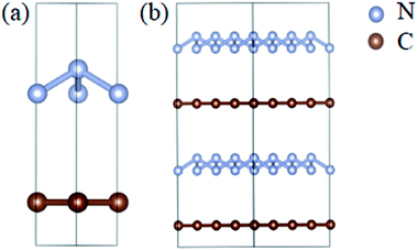
The optimized atomic structures corresponding to the unit cell and supercell (4 × 4 × 2) of A7@graphene system are shown in Fig. 1(a) and (b), respectively. From these two panels, we know that the polymeric nitrogen sheets settles in the middle of graphene sheets and the relaxed distance between the polymeric nitrogen sheets and graphene sheets is 3.905 Å. The N–N bond length of the A7 polymeric nitrogen sheets is 1.58 Å (calculated at 0 GPa), which has a slight change compared to the previously reported theoretical value (1.59 Å)25 due to the nano-confinement effect. The supercell is further used for AIMD simulation calculations.3.2 Structural stability analyses
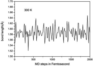
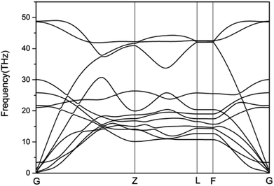
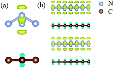
To study the stability of A7@graphene system, two aspect analyses of the molecular dynamic (MD) stability and dynamic stability are carried out respectively. The evolution of bond lengths as a function of time at 300 K is given in Fig. 2, which show that the N–N bond lengths of A7 polymeric nitrogen sheets have a slightly fluctuation but keep constant in the simulation calculation, which demonstrates that the A7@graphene system is stable at ambient pressure and temperature. Significantly, the phonon calculation is carried out at ambient pressure. The phonon spectrum is shown in Fig. 3. No imaginary phonon frequency is found in the whole Brillouin zone at ambient pressure, which means that the hybrid material is dynamically stable under normal pressure. In addition, the zero-temperature atomic relaxation also verifies the stability of A7@graphene at ambient pressure.In order to clarify the physical mechanism of the A7@graphene system stability at ambient conditions, we study the electronic properties of the hybrid material. First, the charge redistribution of the hybrid material is investigated by subtracting electron of the polymeric nitrogen sheets and graphene sheets from the density of A7@graphene system to show the electron distributes due to the charge transfer between polymeric nitrogen sheets and graphene sheets, which are shown in Fig. 4(a) and (b) for the unit cell and supercell (4 × 4 × 2) respectively. From the results we know that the electron density is increased around polymeric nitrogen sheets while decreased near the graphene sheets. Therefore, a certain amount of electrons are transferred from graphene sheets to polymeric nitrogen sheets. Furthermore, by using the Bader charge transfer analysis, it is revealed that there are about 0.0049 electrons transferred to polymeric nitrogen sheets (e/N), which is consistent with the former charge redistribution calculations. The cumulation of negative charges on the nitrogen sheets and positive charges on the graphene sheets give rise to the coulomb interaction between polymeric nitrogen sheets and graphene sheets, which stabilizes the hybrid system at ambient conditions. Similar stabilization mechanism is reported in the case of polymeric nitrogen chains encapsulated in carbon nanotubes (CNT),34 silicon carbide nanotubes (SiCNT),37 and BNNT.43
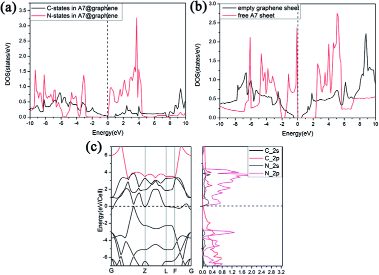
We further study the band structures of A7@graphene system (Fig. 5(a)). To highlight the effects of the interaction between the polymeric nitrogen sheet and graphene sheet, we use the same atomic coordinates as in the relaxed A7@graphene system calculating the band structures of the free polymeric nitrogen sheet and empty graphene sheet, which are shown in Fig. 5(b) and (c) for comparison. Based on the comparison of the calculated band structures, we find that the energy bands of the A7@graphene system are basically the superposition of the energy bands of polymeric nitrogen sheet and graphene sheet, i.e. the lowest three conduction bands of A7@graphene system are from the polymeric nitrogen sheet and the top valence band is from graphene sheet, which shows that no hybridization takes place between these corresponding occupied orbits of the polymeric nitrogen sheet and graphene sheet. Nevertheless, the energy bands of the polymeric nitrogen sheet are rigidly lowered, and graphene sheet are rigidly shifted upward due to the interaction between the guest and host. In addition, we also find that the lowest conduction band of graphene sheet in the A7@graphene system is changed slightly compared to the corresponding energy band of the isolated graphene sheet duo to the charge transfer between polymeric nitrogen sheets and graphene sheets.
 | ||
| Fig. 5 Band structures for (a) the A7@graphene system, (b) the free polymeric nitrogen sheet, and (c) the empty graphene sheet. | ||
Furthermore, we find that there is a weak orbital hybridization between the conduction bands of polymeric nitrogen sheets and graphene sheets. The PDOS for the A7@graphene system is shown in Fig. 6(a) and the PDOS for the free polymeric nitrogen sheets and empty graphene sheets are also shown in Fig. 6(b) for comparison. By contrast, we find that the week orbital hybridization happens at 3.85 eV above the Fermi level (Fig. 6(a)). To ensure the specific hybrid orbits, the band-decomposed charge-density analysis of A7@graphene system is carried out too, which is exhibited in Fig. 6(c). From the results, we know that the week orbital hybridization mainly originates from the N_2p, N_2s orbital and C_2p orbital due to the interaction between the polymeric nitrogen sheets and graphene sheets.
3.3 AIMD simulations analysis
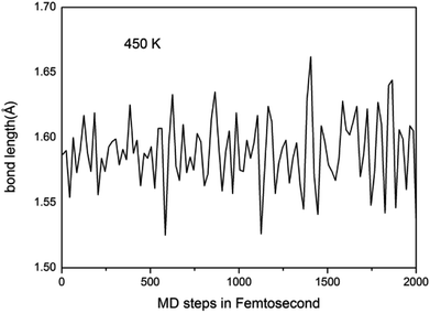
We further study the stable temperature range of the A7@graphene system by AIMD simulations in the temperature range from 300 K to 5000 K for 2 ps time period with the step 50 K or 100 K. The studies show that the bond lengths of polymeric nitrogen sheets have a slight fluctuation but keep constant in the range of temperature (300–450 K), and there is no chemical bonding between the polymeric nitrogen sheets and graphene sheets and the dissociation of polymeric nitrogen sheets, which means that the polymeric nitrogen sheets are stable in the range of temperature (<450 K). The evolution of bond lengths as a function of time at 450 K is given in Fig. 7. When the temperature is above 450 K, the polymeric nitrogen sheets begin to break up into polymeric nitrogen chains and nitrogen gases firstly. When the temperature is higher (1800 K), the polymeric nitrogen sheets are completely dissolved into nitrogen gases and release tremendous energy, as shown in Fig. 8, it is confirmed that the polymeric nitrogen sheets are stable in the range of temperature (<450 K). Compared to previously reported hybrid materials, we find that the A7@graphene system has the lowest decomposition temperature (450 K), such as the dissociation temperature of the polymeric nitrogen chains encapsulated in CNT (>5000 K)35 or BNNT (∼1400 K).43 To understand this difference, we compare A7@graphene with N8@CNT,34 N8@graphene,35 N8@BNNT43 systems systematically. The results are clearly shown in Table 1. From the results, we know that the charge transfer amount in the A7@graphene system (0.0049 e/N) is smaller than that in N8@CNT (0.05 e/N), N8@graphene (0.05 e/N) and N8@BNNT (0.04 e/N). As we know that more charge transfer will lead to a strong electrostatic interaction between the polymeric nitrogen chains and hosting materials, which in turn increases the dissociation temperatures of these hybrid materials, which can be the reason why the A7@graphene has the lowest decomposition temperature compared with other hybrid materials. The smaller charge transfer amount in the A7@graphene system should cause a weaker electron interaction between the polymeric nitrogen sheets and graphene sheets, which is just good for the stabilization of the A7@graphene system at ambient conditions, and favors energy release at a lower temperature, which can be taken as a remarkable advantage of the A7@graphene system. | ||
| Fig. 8 The decomposition path of this hybrid system: (a) 300 K, (b) 450 K, (c) 500 K, (d) 1800 K. The silver-gray and brown spheres are nitrogen atoms and carbon atoms, respectively. | ||
| Hybrid materials | Charge transfer by Bader analysis method | The dissociation temperature |
|---|---|---|
| N8@CNT | 0.05 | >5000 K |
| N8@graphene | 0.05 | >5000 K |
| N8@BNNT | 0.04 | ∼1400 K |
| A7@graphene | 0.0049 | >450 K |
3.4 Energetic properties analysis
Compared with the previously reported one or two-dimensional hybrid materials, such as the N8@CNNT, N8@graphene (the weight ratio of nitrogen are 13.46%, and 20.58%, respectively),34,35 the nitrogen content of the A7@graphene system is significantly improved, and the weight ratio of nitrogen is up to 53.84%, which make it potentially interesting for the applications as a high energy density material. Based on the PBE method,47,48 our calculations shows that the energy difference between the hybrid material and decomposition products is 2.78 eV/A7@graphene system (per unit cell) when the A7 polymeric nitrogen is completely decomposed into nitrogen molecules. The corresponding energy density is 5.2 kJ g−1. In principle, besides energy density, the detonation velocity and detonation pressure are also important for evaluating the energetic properties of energetic material, so we estimate the detonation velocity and detonation pressure by using the Kamlet–Jacobs simi-empirical equation,58 the results are shown in Table 2. Based on the results, we can know that the detonation velocity and detonation pressure of A7@graphene are greatly improved. Thus, the A7@graphene system is a promising candidate for HEDMs.| Compound | The detonation velocities (D) | The detonation pressures (p) |
|---|---|---|
| A7@graphene | 10.94 | 60.95 |
| TNT | 7.37 | 23.46 |
| HMX | 9.11 | 37.32 |
4 Conclusions
In summary, we present a new hybrid structure where polymeric nitrogen sheets are sandwiched between graphene sheets in the form of a three-dimensional crystal. According to theoretical calculations, it is verified that the polymeric nitrogen sheets are stable at ambient pressure and room temperature. Furthermore, the polymeric nitrogen sheets encapsulated in graphene sheets begin to break up into polymeric nitrogen chains or nitrogen gas at above 450 K, and when the temperature is higher (1800 K), the polymeric nitrogen sheets are completely dissolved into nitrogen gases and release tremendous energy. In addition, the new hybrid material has a higher nitrogen content (the weight ratio of nitrogen is up to 53.84%), and the corresponding energy density is 5.2 kJ g−1. The hybrid material has a satisfactory energy density, even considerably improved detonation velocity and detonation pressure compared with the traditional powerful energetic materials (TNT, HMX). Based on the electronic properties, it is confirmed that the lower decomposition temperature is ascribed to the lower charge transfer amount between the polymeric nitrogen sheets and graphene sheets which causes a weaker coulomb interaction compared with other hybrid materials, which is just good for the stabilization of the polymeric nitrogen sheets at ambient conditions, and favors the energy release under a gentle way. Thus our study provides a highly promising method for the capture and application of polymeric nitrogen in a controllable manner.Conflicts of interest
There are no conflicts to declare.Acknowledgements
We acknowledge Zhao Liu, Sen Shao, and Peihao Huang for helpful discussions. This work was financially supported by National Key R&D Program of China (2018YFA0305900) and the NSFC (116344004, 51320105007, 11604116 and 51602124), Program for Changjiang Scholars and Innovative Research Team in University (IRT1132). We also acknowledge the use of computing facilities at the High Performance Computing Centre of Jilin University.References
- M. M. G. Alemany and J. L. Martins, Phys. Rev. B: Condens. Matter Mater. Phys., 2003, 68, 024110 CrossRef.
- W. D. Mattson, D. Sanchez-Portal, S. Chiesa and R. M. Martin, Phys. Rev. Lett., 2004, 93, 125501 CrossRef PubMed.
- F. Zahariev, S. V. Dudiy, J. Hooper, F. Zhang and T. K. Woo, Phys. Rev. Lett., 2006, 97, 155503 CrossRef PubMed.
- A. R. Oganov and C. W. Glass, J. Chem. Phys., 2006, 124, 244704 CrossRef PubMed.
- X. L. Wang, Z. He, Y. M. Ma, T. Cui, Z. M. Liu, B. B. Liu, J. F. Li and G. T. Zou, J. Phys.: Condens. Matter, 2007, 19, 425226 CrossRef.
- K. O. Christe, Propellants, Explos., Pyrotech., 2007, 32, 194–204 CrossRef.
- C. J. Pickard and R. J. Needs, Nat. Mater., 2008, 7, 775–779 CrossRef PubMed.
- X.-Q. Chen, C. L. Fu and R. Podloucky, Phys. Rev. B: Condens. Matter Mater. Phys., 2008, 77, 064103 CrossRef.
- C. J. Pickard and R. J. Needs, Phys. Rev. Lett., 2009, 102, 125702 CrossRef PubMed.
- Y. Ma, A. R. Oganov, Z. Li, Y. Xie and J. Kotakoski, Phys. Rev. Lett., 2009, 102, 065501 CrossRef PubMed.
- X. Wang, Y. Wang, M. Miao, X. Zhong, J. Lv, T. Cui, J. Li, L. Chen, C. J. Pickard and Y. Ma, Phys. Rev. Lett., 2012, 109, 175502 CrossRef PubMed.
- X. Wang, F. Tian, L. Wang, X. Jin, D. Duan, X. Huang, B. Liu and T. Cui, New J. Phys., 2013, 15, 013010 CrossRef.
- F. Zahariev, A. Hu, J. Hooper, F. Zhang and T. Woo, Phys. Rev. B: Condens. Matter Mater. Phys., 2005, 72, 214108 CrossRef.
- J. Zhang, Z. Zeng, H.-Q. Lin and Y.-L. Li, Sci. Rep., 2014, 04358 Search PubMed.
- M. Sun, Y. Yin and Z. Pang, Comput. Mater. Sci., 2015, 98, 399–404 CrossRef.
- F. Peng, Y. Yao, H. Liu and Y. Ma, J. Phys. Chem. Lett., 2015, 6, 2363–2366 CrossRef PubMed.
- F. Peng, Y. Han, H. Liu and Y. Yao, Sci. Rep., 2015, 16902 CrossRef PubMed.
- F. Peng, Y. Wang, H. Wang, Y. Zhang and Y. Ma, Phys. Rev. B: Condens. Matter Mater. Phys., 2015, 92, 094104 CrossRef.
- D. Plašienka and R. Martoňák, J. Chem. Phys., 2015, 142, 094505 CrossRef PubMed.
- M. Frost, R. T. Howie, P. Dalladay-Simpson, A. F. Goncharov and E. Gregoryanz, Phys. Rev. B: Condens. Matter Mater. Phys., 2015, 93, 024113 CrossRef.
- K. Yin, Y. Wang, H. Liu, F. Peng and L. Zhang, J. Mater. Chem. A, 2015, 3, 4188–4194 RSC.
- M. J. Greschner, M. Zhang, A. Majumdar, H. Liu, F. Peng, J. S. Tse and Y. Yao, J. Phys. Chem. A, 2016, 120, 2920–2925 CrossRef PubMed.
- J. Zhang, A. R. Oganov, X. Li and H. Niu, Phys. Rev. B, 2017, 95, 020103 CrossRef.
- Z. Liu, D. Li, S. Wei, W. Wang, F. Tian, K. Bao, D. Duan, H. Yu, B. Liu and T. Cui, Inorg. Chem., 2017, 56, 7494–7500 CrossRef PubMed.
- C. Mailhiot, L. H. Yang and A. K. McMahan, Phys. Rev. B: Condens. Matter Mater. Phys., 1992, 46, 14420–14435 CrossRef.
- J. Uddin, V. Barone and G. E. Scuseria, Mol. Phys., 2006, 104, 745–749 CrossRef.
- M. I. Eremets, A. G. Gavriliuk, I. A. Trojan, D. A. Dzivenko and R. Boehler, Nat. Mater., 2004, 3, 558–563 CrossRef PubMed.
- X. Wang, K. Bao, F. Tian, X. Meng, C. Chen, B. Dong, D. Li, B. Liu and T. Cui, J. Chem. Phys., 2010, 133, 044512 CrossRef PubMed.
- D. Tomasino, M. Kim, J. Smith and C.-S. Yoo, Phys. Rev. Lett., 2014, 113, 205502 CrossRef PubMed.
- A. E. Gash, T. M. Tillotson, J. H. Satcher, J. F. Poco, L. W. Hrubesh and R. L. Simpson, Chem. Mater., 2001, 13, 999–1007 CrossRef.
- C. Zhang, C. Sun, B. Hu, C. Yu and M. Lu, Science, 2017, 355, 374–376 CrossRef PubMed.
- W. Zhang, J. Zhang, M. Deng, X. Qi, F. Nie and Q. Zhang, Nat. Commun., 2017, 8, 181 CrossRef PubMed.
- W. Zhang, K. Wang, J. Li, Z. Lin, S. Song, S. Huang, Y. Liu, F. Nie and Q. Zhang, Angew. Chem., Int. Ed., 2018, 57, 2592–2595 CrossRef PubMed.
- H. Abou-Rachid, A. Hu, V. Timoshevskii, Y. Song and L.-S. Lussier, Phys. Rev. Lett., 2008, 100, 196401 CrossRef PubMed.
- V. Timoshevskii, W. Ji, H. Abou-Rachid, L.-S. Lussier and H. Guo, Phys. Rev. B: Condens. Matter Mater. Phys., 2009, 80, 115409 CrossRef.
- W. Ji, V. Timoshevskii, H. Guo, H. Abou-Rachid and L.-S. Lussier, Appl. Phys. Lett., 2009, 95, 021904 CrossRef.
- F. Zheng, C. Wang and P. Zhang, J. Comput. Theor. Nanosci., 2012, 9, 1129–1133 CrossRef.
- I. K. M. Law, L. Liu, A. Xu, K. S. L. Lam, P. M. Vanhoutte, C.-M. Che, P. T. Y. Leung and Y. Wang, Proteomics, 2009, 9, 2444–2456 CrossRef PubMed.
- D. W. Chang, E. K. Lee, E. Y. Park, H. Yu, H.-J. Choi, I.-Y. Jeon, G.-J. Sohn, D. Shin, N. Park, J. H. Oh, L. Dai and J.-B. Baek, J. Am. Chem. Soc., 2013, 135, 8981–8988 CrossRef PubMed.
- W. Xu, T.-S. Lim, H.-K. Seo, S.-Y. Min, H. Cho, M.-H. Park, Y.-H. Kim and T.-W. Lee, Small, 2014, 10, 1999–2005 CrossRef PubMed.
- Y.-F. Lu, S.-T. Lo, J.-C. Lin, W. Zhang, J.-Y. Lu, F.-H. Liu, C.-M. Tseng, Y.-H. Lee, C.-T. Liang and L.-J. Li, ACS Nano, 2013, 7, 6522–6532 CrossRef PubMed.
- Y. Xu, Q. Wang, C. Shen, Q. Lin, P. Wang and M. Lu, A series of energetic metal pentazolate hydrates, Nature, 2017, 549, 78–81 CrossRef PubMed.
- S. Liu, M. Yao, F. Ma, B. Liu, Z. Yao, R. Liu, T. Cui and B. Liu, J. Phys. Chem. C, 2016, 120, 16412–16417 CrossRef.
- H. Lv, M. yao, Q. Li, R. Liu, B. Liu, Z. Yao, D. Liu, Z. Liu, J. Liu, Z. Chen, B. Zou, T. Cui and B. Liu, Sci. Rep., 2014, 13234 Search PubMed.
- Z. Wu, E. M. Benchafia, Z. Iqbal and X. Wang, Angew. Chem., 2014, 126, 12763–12767 CrossRef.
- G. Kresse and J. FurthmÜller, Phys. Rev. B: Condens. Matter Mater. Phys., 1996, 54, 0163–1829 CrossRef.
- J. P. Perdew, A. Ruzsinszky, G. I. Csonka, O. A. Vydrov, G. E. Scuseria, L. A. Constantin, X. Zhou and K. Burke, Phys. Rev. Lett., 2008, 100, 136406 CrossRef PubMed.
- A. Vanderlei dos Santos, G. Padilha and M. Monçalves, Solid State Sci., 2012, 14, 269–275 CrossRef.
- J. H. Monkhorst and D. J. Pack, Phys. Rev. B: Solid State, 1976, 13, 5188–5192 CrossRef.
- J. Klimeš, D. R. Bowler and A. Michaelides, Phys. Rev. B: Condens. Matter Mater. Phys., 2011, 83, 195131 CrossRef.
- K. Lee, É. D. Murray, L. Kong, B. I. Lundqvist and D. C. Langreth, Phys. Rev. B: Condens. Matter Mater. Phys., 2012, 82, 081101 CrossRef.
- X. Wang, F. Tian, L. Wang, T. Cui, B. Liu and G. Zou, J. Chem. Phys., 2010, 132, 024502 CrossRef PubMed.
- S. V. Bondarchuk and B. F. Minaev, Comput. Mater. Sci., 2017, 133, 122–129 CrossRef.
- Y. Hu, P. Huang, L. Guo, X. Wang and C. Zhang, Phys. Lett. A, 2006, 359, 728–732 CrossRef.
- M. Ghosh, L. Wang and S. A. Asher, Appl. Spectrosc., 2012, 66, 1013–1021 CrossRef.
- W. Tang, E. Sanville and G. Henkelman, J. Phys.: Condens. Matter, 2009, 21, 084204 CrossRef PubMed.
- A. Togo, F. Oba and I. Tanaka, Phys. Rev. B: Condens. Matter Mater. Phys., 2008, 78, 134106 CrossRef.
- G. X. Wang, H. M. Xiao, X. H. Ju and X. D. Gong, Acta Chim. Sin., 2007, 6, 517–524 Search PubMed.
| This journal is © The Royal Society of Chemistry 2018 |

