 Open Access Article
Structure transformation by sp2 hydrocarbon assisted carbon nanotube growth†
Sook Young Moon *a,
Woo Sik Kimb and
Chung Soo Kimc
aInstitute of Advanced Composite Materials, Korea Institute of Science and Technology (KIST), Jeonbuk 55324, Republic of Korea. E-mail: moon.sookyoung@kist.re.kr
bCeramic Fiber & Composite Center, Korea Institute of Ceramic Engineering & Technology, Gyeongsangnam-do 52851, Republic of Korea
cAnalysis & Certification Center, Korea Institute of Ceramic Engineering & Technology, Gyeongsangnam-do 52851, Republic of Korea
First published on 18th July 2018
Abstract
In this study, we investigated the effect of hydrocarbon species composition on carbon nanotube (CNT) growth using an iron catalyst by chemical vapor deposition. The atomic hydrogen and active carbon species from hydrocarbon affect to the nucleation and growth of CNT arrays. With increasing atomic hydrogen content, the interface layer distance of the CNTs decreased from 3.7 to 3.4 Å. The shifts in the G-band in the Raman spectra of the CNTs indicated that the hydrogen atoms affected the generation of C–C bonds in graphene layers.
Introduction
Carbon nanotubes (CNTs) have remarkable electrical, thermal, mechanical, optical, and mechanical properties.1–8 CNTs are promising reinforcement materials for composite materials because of their high mechanical properties. Numerous researchers have reported the preparation and characterization of high-strength and high-performance CNT/polymer composites.9–12 However, the short length of CNTs has impeded their commercial use in structural materials. Owing to these reasons, many researchers have focused on spinnable CNT arrays since these arrays were first reported by researchers at Tsinghua University.13 The use of direct-spun CNTs represents a viable approach for improving the properties of composite materials. However, most spun CNTs exhibit poor crystallinity and short length because of their waviness.In our previous study, we investigated the mechanism of spinnability by studying the relationship between spinning parameters and the properties of CNT arrays.14 We proposed two halide systems to improve the spinnability of CNT arrays. We found that the spinning properties of CNT arrays are clearly related to their waviness and density. Ideally, CNT arrays should exhibit both an appropriate waviness and density for spinning. However, the waviness is also related to crystallinity. Thus, maintaining spinnability while simultaneously achieving high crystallinity is difficult.
On the other hand, Hata et al. reported a water-assisted synthesis of high purity single-walled carbon nanotubes (SWCNTs) in 2004.15 They proposed that steam removed amorphous carbon during the CVD process which reacts as a weak oxidizer. The ethylene and water with appropriate composition were critical for maximizing the catalyst lifetime. However, Zhong et al. reported that an etchant to remove amorphous carbon, such as water, is not necessary in cold-wall CVD when the activity of hydrocarbon is low.16 This studies investigated the carbon precursor is most important factor in CNT growth. Thus, the selection of a carbon precursor can dramatically increase both the catalyst's lifetime and the CNT growth condition. Li et al. studied the effect of hydrocarbon precursors on the formation of CNTs. They used organic hydrocarbon source, such as benzene, hexane, naphthalene etc. The synthesized CNTs shows different properties by hydrocarbon sources.17 However, in this case, the CNT arrays don't have a spinning properties. Therefore, the development of an effective method for improving the crystallinity of spinnable CNT arrays remains a major challenge to our purpose.
In this study, we investigate the CNT growth process to improve the crystallinity of spinnable CNT arrays using additional hydrocarbon source. In previous research, Nozaki et al.18 used a mixture of CH4 and C2H2 to determine a higher contribution of C2 to the final nanotube structure; however, details of intermediate processes were not obtained. We synthesized CNT arrays via a thermal CVD process with various concentration ratios between the hydrocarbon sources (concentration ratio R = [C2H4]/[C2H2]). Most method to make spinnable CNT arrays used only one hydrocarbon source. They are controlled other condition such as carrier gas,19 temperature, catalyst,14 and introducing buffer layer,20 etc., but our proposed method is very simple and effective. All of the growth conditions were the same other than the hydrocarbon contents.
Materials and methods
The spinnable CNT arrays were synthesized according to our previously reported method.14 Briefly, the arrays were synthesized via a CVD process at 825 °C using acetylene (C2H2) and ethylene (C2H4) as the carbon sources. The catalyst used two halide system using x = 0.3 [xFeCl3![[thin space (1/6-em)]](https://www.rsc.org/images/entities/char_2009.gif) :
:![[thin space (1/6-em)]](https://www.rsc.org/images/entities/char_2009.gif) (1 − x)FeCl2] ratio. The morphologies of the CNTs were observed via field-emission scanning electron microscopy (FE-SEM, Hitachi S-4700) and field-emission transmission electron microscopy (FE-TEM, FEI-Tecnai G2 F20, 200 kV). The spinnability of each CNT arrays was tested by spindle rotating system. The crystalline characteristics of the CNTs were analyzed via Raman spectroscopy (LabRAM HR Evolution, Horiba) using the 523 nm laser. CNT purity was determined via thermogravimetric analysis (TGA, TGA-6300, SII, Japan).
(1 − x)FeCl2] ratio. The morphologies of the CNTs were observed via field-emission scanning electron microscopy (FE-SEM, Hitachi S-4700) and field-emission transmission electron microscopy (FE-TEM, FEI-Tecnai G2 F20, 200 kV). The spinnability of each CNT arrays was tested by spindle rotating system. The crystalline characteristics of the CNTs were analyzed via Raman spectroscopy (LabRAM HR Evolution, Horiba) using the 523 nm laser. CNT purity was determined via thermogravimetric analysis (TGA, TGA-6300, SII, Japan).
Results and discussion
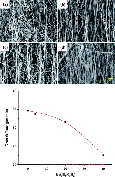
Fig. 1 shows CNT arrays synthesized with various R values. The diameters and lengths of the synthesized CNTs range from 25 to 60 nm and from 680 μm to 1.03 mm, depending on R. The high concentrations of atomic hydrogen generated by hydrocarbon decomposition reduced the C–C diffusion rate on the catalyst surface. Therefore, the growth rate decreased with increasing R. The synthesized CNT arrays also show a linear morphology with increasing R. The entanglement and waviness are most extensive in the sample prepared with R = 0. The waviness of CNTs is caused by defects on their graphene sheets; such defects are caused by various effects during the CVD process. Among these effects, catalyst deactivation is prominent. When the imbibed catalyst is halted inside a CNT, some graphene layers close at this point, while other graphene layers grow continuously. These halted catalyst points inner tube induce curling of the CNTs. Therefore, increasing catalyst reactivity is important to achieve high-structural quality CNTs. In the present work, increasing the R values resulted in a linear CNT morphology, which means that the atomic hydrogen affected the activity of the catalyst. Moreover, the poisoning of the catalyst by unsaturated carbon decreased. Consequently, the CNT morphology was linear; thus, the composition of the hydrocarbon source affected the morphological properties of the CNTs, including their alignment, diameter, and length. However, the growth rate decreased with increasing C2H4. C2H2 is a more reactive species, particularly for gas-phase rearrangements (i.e., self-polymerization and formation of soot at high loadings), as compared to C2H4. Therefore, C2H2 has higher carbon formation yield at lower temperature.21 At the beginning of the growth process, the growth rate is high, but after a while and by poisoning the catalyst, growth rate reduced. Indeed, in our previous experiment, the growth limitation was 30 min at R = 0, whereas we could be confirmed growth up to 60 min at R = 40 (Fig. S1†). | ||
| Fig. 1 SEM images of CNT arrays synthesized with various R values: (a) R = 0, (b) R = 4, (c) R = 20, and (d) R = 40. | ||
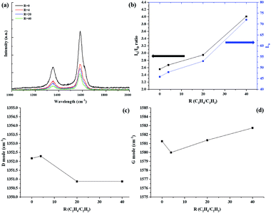
Fig. 2 shows the Raman spectra of the CNTs prepared with different R values. All samples show two clear peaks at ∼1352 and 1581 cm−1, which indicate the D-band (sp3) which indicate disorder in the graphene layer, and G-band (sp2) which indicates crystalline graphitic layers, of CNTs, respectively.22–24 Thus, the intensity ratio of IG/ID can be used to determine the crystallinity of carbon materials. The IG/ID ratio increased with increasing R. The IG/ID ratio shows a correlation with the degree of waviness: the straight part shows a high IG/ID ratio, and the wavy part shows a low IG/ID ratio. Thus, the wavy regions have more defects than the straight region. The peak at about 1617 cm−1 (the D′ peak) also determined the disorder,25 and the intensity of this peak decreased with increasing R, which well matched with increasing IG/ID. The IG/ID ratio also used to calculate the in-plane sp2 crystallite size, La. We calculated La using the following equation:26,27
 | (1) |
 | ||
| Fig. 2 Raman spectra of the CNTs prepared with different R values; (a) Raman spectroscopy, (b) IG/ID and La values with R, (c), and (d) G-band/D-band peak frequencies as functions of R, respectively. | ||
The La changed from 45.79 to 72 as the R was varied. The largest La of 72 nm was obtained at R = 40. A general mechanism of supported-catalyst CNT growth is proposed as follows: (1) the catalyst melted. (2) The hydrocarbon decomposed, and atomic carbon diffused onto the catalyst particles. (3) The carbon atoms continuously accumulated. The additional hydrogen-rich hydrocarbon decomposed and generated H atoms, thus causing the number of C–H bonds to increase continuously and requiring additional time for the formation of C–C bonds. Therefore, the growth rate decreased from 34.7 μ min−1 to 22.7 μ min−1. This behavior suggests that atomic H can break unsaturated bonds on the catalyst surface during CNT growth, thus occurring structural transformations. This behavior is consistent with the tendency of the IG/ID ratio to increase with increasing R.
In addition, the G-mode caused by the bond stretching of all pairs of sp2 atoms in both rings and chains. The peak shift of the G-mode can be associated with axial elongation/shortening of the C–C bonds in a nanotube shell. The G-mode peaks slightly upshifted by approximately 1.49 cm−1 with increasing R in Fig. 2. This upshift is associated with shortening of the C–C bond resulting from the structure. Xie et al. have reported that the G-band red-shifts linearly with increasing number of layers on graphene and that the disoriented stacked layers also induce a red shift of the G-band.28 These results suggest that the effect of changing stacking layers on catalyst surface during CNT growth would have affected to C–C bond, thus causing the G peak to shift. However, in our cases, we thought that the C–C bond more shortened and tighten with increasing R than R = 0. Because the graphene is 2D material but CNT is 1D material, so the physical reaction is different. Our assumption can be proven in TEM analysis.
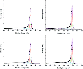
Fig. 3 shows the effect of the hydrocarbon source on the synthesized CNT surfaces. The spectra of C 1s were analyzed by Gaussian peak fitting and the peaks appeared at about 284.2, 284.5, 285.4, and 291.6 eV, which correspond to C![[double bond, length as m-dash]](https://www.rsc.org/images/entities/char_e001.gif) C (sp2), C–C (sp3), C–O, and π–π* bonding, respectively.29 The C
C (sp2), C–C (sp3), C–O, and π–π* bonding, respectively.29 The C![[double bond, length as m-dash]](https://www.rsc.org/images/entities/char_e001.gif) C/C–C ratio increased with increasing R. The increase in the C
C/C–C ratio increased with increasing R. The increase in the C![[double bond, length as m-dash]](https://www.rsc.org/images/entities/char_e001.gif) C/C–C ratio represents a decrease in the amorphous carbon and unsaturated dangling bonds. With increasing R, atomic hydrogens are present during the CNT growth process as a result of reduced catalyst surface poisoning and the high crystallinity of the CNT arrays.
C/C–C ratio represents a decrease in the amorphous carbon and unsaturated dangling bonds. With increasing R, atomic hydrogens are present during the CNT growth process as a result of reduced catalyst surface poisoning and the high crystallinity of the CNT arrays.
The O 1s spectrum was investigated to investigate the oxide species on the CNT surfaces (Fig. S3†). The O 1s spectra shows two main peaks at about 531.5 eV (C![[double bond, length as m-dash]](https://www.rsc.org/images/entities/char_e001.gif) O) and 533.1 eV(C–O(H)), which also analyzed by Gaussian peak fitting. The concentration of hydroxyl group (C–O) decreased with increasing R because of absence of amorphous carbon.
O) and 533.1 eV(C–O(H)), which also analyzed by Gaussian peak fitting. The concentration of hydroxyl group (C–O) decreased with increasing R because of absence of amorphous carbon.
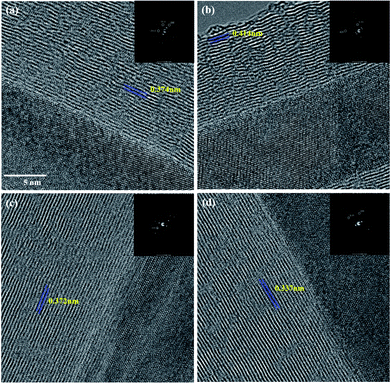
Fig. 4 shows the transmission electron microscopy (TEM) images of the CNTs with various R values. The layers in the R = 0 shows an imperfect graphitic layer structure having some cavities (Fig. 4a). Hou et al. and our previous study defined the discontinuous graphene stack as a carbon island, which have several dangling bonds.30,31 But, the atomic hydrogen continuously removed unsaturated carbon species; therefore, the graphene layer on the catalyst surface rearranged and exhibits regular forms with increasing R. The layers distance of CNTs decreased from 3.7 Å to 3.4 Å as the defectiveness of the structure decreased. We speculated that the atomic hydrogen etched the unsaturated bond on the catalyst surface and that the decomposed carbon atoms diffused slowly to form a perfect graphene layer. This assumption is consistent with the IG/ID enhancement observed in the Raman spectra. All iron particles structures assigned γ-Fe.
 | ||
| Fig. 4 TEM images of synthesized CNT arrays with various R values: (a) R = 0, (b) R = 4, (c) R = 20, and (d) R = 40. | ||
Table 1 displays the spinnability of the CNT arrays as a function of R. We observed that, as the width of the wavy region increased, the spinnability of the CNT arrays decreased. This observation is consistent with results we reported elsewhere.14 The synthesized CNT arrays show a straighter morphology with increasing R. Thus, the spinnability increased with increasing R. The optical image shows the spinnability between R = 0 and R = 40. In case of R = 0, the CNT fiber was broken during pulled out.
Conclusions
In conclusion, we investigated the effects of an additional hydrocarbon source on spinnable CNTs. The use of two hydrocarbon sources influenced the morphology and crystallinity of the grown CNTs. The waviness decreased with increasing R, which resulted in increased crystallinity and spinnability. The atomic hydrogen from the hydrocarbon promoted the growth of nanotubes with hexagonal networks without any defects. Thus, the crystallinity increased with increasing R. The obtained CNT arrays exhibited good spinnability.Conflicts of interest
There are no conflicts to declare.Acknowledgements
This study was supported by grants from the Korea Institute of Science and Technology (KIST) Open Research Program (ORP), the Industrial Fundamental Technology Development Program (No. 10052838, development of the direct spinning process for continuous carbon nanotube fiber) funded by the Ministry of Trade, Industry and Energy (MOTIE).Notes and references
- A. Leckawa-Raus, J. Patmore, L. Kurzepa, J. Bulmer and K. Koziol, Adv. Funct. Mater., 2014, 24, 3661 CrossRef
.
- M. Miao, Carbon, 2011, 49, 3755 CrossRef
.
- X. Zhang, S. Li, L. Cai, X. Tian, Q. Zhang, X. Qi, W. Zhou, N. Zhang, F. Yang, Q. Fan, Y. Wang, H. Liu, X. Bai, W. Zhou and S. Xi, Light: Sci. Appl., 2015, 4, e318 CrossRef
.
- A. Sharma, V. Singh, T. L. Bougher and B. A. Cola, Nat. Nanotechnol., 2015, 10, 1027 CrossRef PubMed
.
- B. Arash, Q. Wang and V. K. Varadan, Sci. Rep., 2014, 4, 6479 CrossRef PubMed
.
- A. M. K. Esawi, K. Morsi, A. Sayed, M. Taher and S. Lanka, Compos. Sci. Technol., 2010, 70, 2237 CrossRef
.
- Q. Liao, Z. Liu, W. Liu, C. Deng and N. Yang, Sci. Rep., 2015, 5, 16543 CrossRef PubMed
.
- E. Mayhew and V. Prakash, J. Appl. Phys., 2014, 115, 174306 CrossRef
.
- J. A. Coleman, U. Khan, W. J. Blau and Y. K. Gun'ko, Carbon, 2006, 44, 1624 CrossRef
.
- E. T. Thostenson, Z. Ren and T. W. Chou, Compos. Sci. Technol., 2001, 61, 1899 CrossRef
.
- B. L. Wardle, D. S. Saito, E. J. Gracia, A. J. Hart, R. G. Villoria and E. A. Verploegen, Adv. Mater., 2008, 20, 2707 CrossRef PubMed
.
- A. Eitan, K. Jiang, D. Dukes, R. Andrews and L. S. Schadler, Chem. Mater., 2003, 15, 3198 CrossRef
.
- K. Jiang, Q. Li and S. Fan, Nature, 2002, 419, 801 CrossRef PubMed
.
- S. Y. Moon, RSC Adv., 2015, 5, 84367 RSC
.
- K. Hata, D. N. Futaba, K. Mizuno, T. Namai, M. Yumura and S. Iijima, Science, 2004, 306, 1362 CrossRef PubMed
.
- G. Zhong, S. Hofmann, F. Yan, H. Telg, J. H. Warner, D. Eder, C. Thomsen, W. I. Milne and J. Robertson, J. Phys. Chem. C, 2009, 113, 17321 CrossRef
.
- Q. Li, H. Yan, J. Zhang and Z. Liu, Carbon, 2004, 42, 829 CrossRef
.
- T. Nozaki, S. Yoshida and K. Okasaki, ISPC, Philadelphia, 2012; 20, p. 16 Search PubMed
.
- Q. Zhang, D. G. Wang, J. Q. Huang, W. P. Zhou, G. H. Luo, W. Z. Qian and F. Wei, Cabron, 2010, 48, 2855 CrossRef
.
- Y. Zhang, G. Sun, Z. Zhan and L. Zheng, J. Mater. Sci., 2017, 52, 6196 CrossRef
.
- W. Shi, K. Xue, E. R. Meshot and D. L. Plata, Green Chem., 2017, 19, 3787 RSC
.
- A. Jorio, R. Saito, C. M. Lieber, M. Hunter, T. McClure, G. Dresselhaus and M. S. Dresselhaus, Phys. Rev. Lett., 2001, 86, 1118 CrossRef PubMed
.
- C. J. Lee, J. Park, Y. Huh and J. Y. Lee, Chem. Phys. Lett., 2001, 343, 33 CrossRef
.
- M. J. Matthews, M. A. Pimenta, G. Dresselhaus, M. S. Dresselhaus and M. Endo, Phys. Rev. B: Condens. Matter Mater. Phys., 1999, 59, R6585 CrossRef
.
- A. M. Rao, A. Jorio, M. A. Pimenta, M. S. S. Dantas, R. Saito, G. Dresselhaus and M. S. Dresselhaus, Phys. Rev. Lett., 2000, 84, 1820 CrossRef PubMed
.
- M. Pumera and H. Iwai, J. Phys. Chem. C, 2009, 113, 4401 CrossRef
.
- S. Sanchez, E. Fabregas and M. Pumera, Phys. Chem. Chem. Phys., 2009, 11, 182 RSC
.
- X. Xie, L. Ju, X. Feng, Y. Sun, R. Zhou, K. Liu, S. Fan, Q. Li and K. Jiang, Nano Lett., 2009, 9, 2565 CrossRef PubMed
.
- T. I. T. Okpalugo, P. Papakonstantinou, H. Murphy, J. McLaughlin and N. M. D. Brown, Carbon, 2005, 43, 153 CrossRef
.
- P. X. Hou, S. T. Xu, Z. Ying, Q. H. Yang, C. Liu and H. M. Cheng, Carbon, 2003, 41, 2471 CrossRef
.
- S. Y. Moon, RSC Adv., 2016, 6, 79401 RSC
.
Footnote |
| † Electronic supplementary information (ESI) available. See DOI: 10.1039/c8ra04244f |
| This journal is © The Royal Society of Chemistry 2018 |


