 Open Access Article
Understanding the tribological impacts of alkali element on lubrication of binary borate melt†
Bach H. Tran a,
Kiet Tieua,
Shanhong Wan*a,
Hongtao Zhu
 a,
Shaogang Cuia and
Liping Wang
 b
b
aFaculty of Engineering and Information Sciences, University of Wollongong, Northfields Avenue, Wollongong, NSW 2522, Australia. E-mail: shanhong@uow.edu.au
bNingbo Institute of Materials Technology and Engineering, Chinese Academy of Sciences, Ningbo 315201, China
First published on 14th August 2018
Abstract
Melt lubricants have been regarded as an effective class to deliver lubrication on moving mechanical contacts at extreme temperatures. Among the elementary constituents, alkali elements play a critical role in governing the physical–chemical characteristics of the lubricant despite the obscurity regarding their intrinsic roles on the rubbing interfaces. The present study attempts to unfold the effects of sodium on the tribological responses of mating steel pair under borate melt lubrication. It has been found that the involvement of Na inspires a total reversal in lubricating potentials of the lone B2O3 melt manifested by remarkable friction reduction, wear inhibition and prolonged load-bearing capacity. These exceptional performances are attributed to the accretion of nanothin Na layers on the contact interfaces. The interfacial occurrences are interpreted from a physico-chemistry perspective while the influences of surface microstructure are also discussed in detail. Multiple characterizations are employed to thoroughly examine the sliding interfaces in multi-dimensions including Scanning Electron Microscopy (SEM), Scanning Transmission Electron Microscopy (STEM) and Atomic Force Microscopy (AFM). In addition, chemical fingerprints of relevant elements are determined by Energy Dispersive Spectroscopy (EDS) and Electron Loss Energy Spectroscopy (EELS).
1. Introduction
High-temperature tribology conveys the understanding of complex interfacial phenomena on contact surface under the effect of extreme heat. In practice, hot metal forming processes have been benefited from the significances generated from the interdisciplinary subject. The main thermal factor in conjunction with severe shearing entails surface oxidation and mounting friction while catastrophic wear has degraded service life of the mechanical components which is equivalent to impaired operation yield. Lubrication has been conventionally employed to mitigate those rising concerns and melt lubricants established themselves as one of the most promising candidates with their outstanding performances.1Melt lubricants are principally inorganic glassy compounds which can act as an effective lubricating body upon their melting. The thermally-induced transition triggers viscous and liquid-like characteristics of the original substance which produces desirable lubricating functions. The acting mechanism is dependent closely on the chemical nature of the melt under extreme conditions that vary greatly from one to another. A bi-alkaline polyphosphate has reportedly delivered friction-reducing and wear-resistant effects on steel tribopair at 800 °C.2–4 The hierarchical structure of tribologically-induced boundary film was proposed to be the core factor dictating the excellent properties of phosphate-based lubricant.3 Besides good lubricity,5,6 boron derivatives are believed to provide anti-oxidation capacity on the rubbing interface.7 Silicate is able to lower friction coefficient on steel contact up to 1000 °C due to its superior thermal stability.8
From chemistry point view, melt lubricant can be formulated from two primary constituents: alkaline (or even alkaline-earth) element and glass-forming compound. Each of the composition has certain roles in defining the overall physico-chemical characteristics of the compound at elevated temperature. Condensed polyphosphate (P2O5), boron oxide (B2O3) and silicon oxide (SiO2) are the most fundamental representatives of network-building blocks. With high mutual connectivity, those structural groups are the foundations of polymeric nature that renders thermal stability and high transition point. The introduction of cationic moieties modifies the degree of polymerization which helps tuning physical attributes including melting temperature, viscosity. Adjusting relative ratio of the two components spontaneously alters high-temperature behaviors of the melt and there have been plenty of studies dedicated to this intimate relationship.9–12 On the rubbing interfaces, how individual class responds to tribological stimulation determines directly the overall lubrication mechanism. For instance, the polymeric frameworks are able to self-disintegrate by reacting with iron oxides debris under polyphosphate lubrication. The depolymerization reaction actively accommodates abrasive particles upon which the anti-wear capacity thrives.13–15 On steel pair lubricated by borate, the boron oxides highly concentrates in the form of a compact and robust boundary film to withstand direct asperity contacts.7 Although the tribological behaviors of network-forming constituents have been understood in some extent, there remain unanswered questions surrounding the roles of alkali elements in melt lubrication.
The current work aims to deconvolute the tribological impacts of an alkali element (sodium – Na) on mating steel pair exposed to borate lubrication at elevated temperature by pin-on-disk testing. Friction and wear characteristics of B2O3 lubrication was evaluated as a reference in comparison to those of its Na-bearing counterpart, a binary system of Na2O–B2O3. The relative locality of the alkali element on both sliding interfaces was determined to reveal its potential functionalities while the acting mechanism is interpreted from physico-chemistry point view. Effects of microstructure of the mating surfaces on the interfacial phenomena are also taken into account.
2. Experimental methodology
2.1 Thermal analysis of lubricants and characterization of high speed steel material
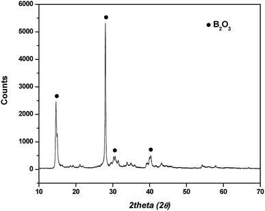
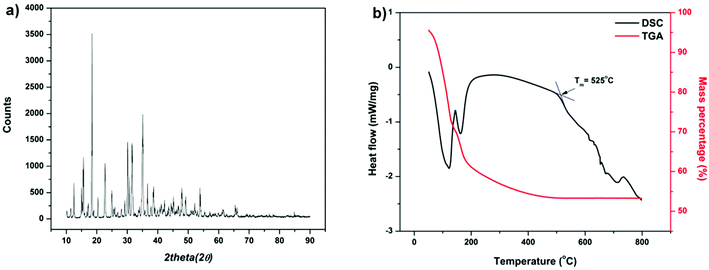
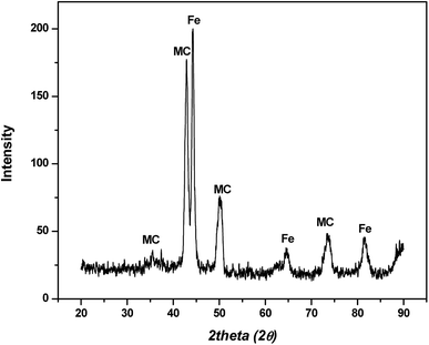
In hot friction test, B2O3 and binary oxides Na2O–B2O3 were evaluated regarding their tribological performances. Fig. 1 shows XRD pattern of the crystalline boron oxide. Thermal behaviors of boron oxide were thoroughly studied as the substance shows a well-defined transition point of 450 °C.6,16 The starting material of binary-oxides was chosen in the form of a crystalline sodium borate – Na2B4O7·10H2O (Fig. 2a) which melts around 525 °C according to thermal analysis TGA/DSC (Fig. 2b). As the tribotests were carried out at 800 °C which exceeds both of the transition points aforementioned, the lubricants readily melt into their liquid-like states. Aqueous solution of 5% wt was prepared for high-temperature lubrication test. Despite formation of boric acid (H3BO3) by the reaction with water, thermal decomposition eventually results in glassy boron oxide6 at the testing temperature. In a similar fashion, with dehydration occurring at 150–200 °C (Fig. 2b), the final composition of sodium borate melt is simplified as Na2O–B2O3 in the hot friction test. The effect of stoichiometry is not within the scopes of the present study since the melting point shifts with Na2O/B2O3 ratio. Thermal transitions of the concerning lubricants are described as followed:As High Speed Steel (HSS) has been predominantly used as the work roll material in practice,17–19 the current study employs HSS as the upper pin. Nominal chemical composition of HSS material is shown in Table 1 with the volume fraction of carbides estimated at 9–12%. There are a number of possible primary carbides formation (denoted as MxCy) in HSS whereas M stands for carbide forming element (such as V, Cr, W or Mo) while C stands for carbon. Although XRD single-handedly cannot distinguish those individual phases (Fig. 3), classification can be made through microstructure observation20 and the signature morphologies of corresponding carbide are illustrated in Fig. 4a–c. On a polished HSS substrate, AFM height profile (Fig. 4d) details protruding dendritic features of the carbide from steel matrix due to the superior hardness of the former phase.
| C | Ni | Mn | Cr | Mo | V | W | Si | P | S | Fe |
|---|---|---|---|---|---|---|---|---|---|---|
| 1.96 | 0.78 | 1.26 | 4.85 | 4.47 | 4.00 | 3.40 | 0.99 | 0.028 | 0.034 | Remainder |
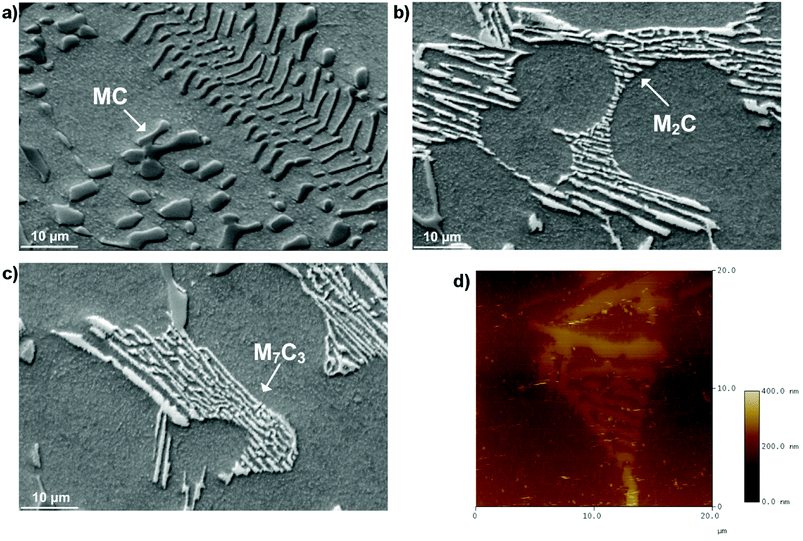 | ||
| Fig. 4 SEM micrographs of different carbide morphologies (a) MC, (b) M2C, (c) M7C3 and (d) AFM height profile of a polished HSS substrate. | ||
2.2 Tribo-pair preparation
Commercial stainless steel (SUS316, hardness of 79 Rockwell B, Young modulus of 193 GPa) was chosen as the rotational component in the hot friction test. The SUS316 round disc is 3 mm thick with a diameter of 50 mm and its surface was polished to achieve a roughness of approximately 1 μm. Mild-carbon steel (grade 1045, 0.2% C with a hardness of 235 HV) was also prepared via the above procedure for disc material. HSS pin was extracted from actual work roll material. The steel matrix has a hardness of 9 ± 3 GPa and a Young modulus of 222 ± 5 GPa while the corresponding values for carbides are 11.3–20.7 GPa and 300–373 GPa depending on different type. A 4 mm-long pin with a 3.175 mm-radius hemispherical end was selected as the stationary part. In an attempt to record the temperature development of the HSS pin during pre-oxidation stage and sliding duration, a thermocouple was embedded inside the pin body which is located at 2 mm above its contact curvature. The steel pairs were ultrasonically cleaned by ethanol and acetone prior to each friction test.2.3 High-temperature tribology testing
High-temperature friction test was performed on a UMT2-CETR ball-on-disc tribometer. The SUS316 disc was first installed into the furnace chamber followed by sequential heating phases to 800 °C. Once the furnace temperature reached the set point, the upper stage carrying HSS pin was automated to descend to a distance of 3 mm away from the disc surface. Pre-oxidation of HSS pin lasted for 15 minutes and temperature development was recorded (Fig. S1†). During this stage, the disc rotated at 5 rpm to ensure uniform heat distribution. The whole system was enabled to stabilize before the sliding started. Lubricant solution was dropped onto the heated disc at 2 minutes before contact engagement with an estimated rate of 0.01 ml s−1 through an auxiliary system. Sliding velocity was kept constant at 0.1 m s−1 while testing duration was fixed at 5 minutes. The applied load varies from 10–40 N (with an interval of 10 N) corresponding to maximum Hertzian contact pressure ranging from 1.16 GPa to 1.84 GPa. The evolution of normal force and lateral force were automatically recorded over the course of sliding and friction coefficients were calculated accordingly. The friction tests were reproduced at least three times and average results were presented. When the friction test terminates, the tribopairs were retrieved immediately and cooled in the air to inhibit additional oxidation and preserve the intrinsic chemical state of the contact interfaces.2.4 Characterization
Wear loss volume of the track was measured by a Surface Profiler (Hommel Etamic W10, JENOPTIK) after the steel discs were gently washed multiple times with distilled water. X-ray Diffractometer (GBC MMA) with Cu-Kα source and a step size of 0.02° was used to determine phase constitution of the as-received lubricant powders and HSS material. The operating voltage and current of the X-ray were selected at 35 kV and 28.6 mA, respectively. Thermal analysis of sodium borate was carried out on a Differential Scanning Calorimetry (NETZSCH STA 449DSC). The analysis was performed using a Rh/Pt crucible under argon atmosphere at a heating rate of 10 °C min−1. An Atomic Force Microscopy (Digital Instrument Dimensions 3100) was employed to generate height profiles of polished HSS substrate and lubricated track.Morphologies of the worn surfaces were examined by a JOEL JSM-6490LV Scanning Electron Microscopy (SEM) equipped with Energy Dispersive Spectroscopy (EDS). Since the lubricant is composed of light elements, low accelerating voltage (7 keV) was selected to intensify the signal yield. Despite the narrow gap between characteristics X-ray energy of B and C (mostly from contamination), they are visibly distinguishable in EDS spectrum. In SEM images, S.D stands for sliding direction.
Specimens for STEM work were prepared by a Dual Beam FEI Helios NanoLab G3 CX (FIB) using gallium ion source. Prior to targeted milling, a thin layer of Pt was deposited on the region of interest for extra protection. The thin foils were extracted from the contact areas parallel to sliding direction on both steel counterparts. Routine polishing with various beam currents ensures appropriate lamellar thickness for microstructural observation and EELS analysis. The specimens were stored in the vacuum chamber of the FIB until further characterization to avoid contamination. The cross sections of the tribo-interfaces were observed by an aberration-corrected JOEL ARM 200F Scanning Transmission Electron Microscopy (STEM) at 200 keV with SDD EDS detector enabling elemental mapping with atomic resolution. X-ray analysis was performed using NORAN System X-ray analysis and additional procedure for quantitative extraction was employed in both EDS mapping and line scanning. Phase mapping involves comparison of X-ray spectrum between pixels and those share similar statistic are assembled into one specific phase. Electron Energy Loss Spectroscopy (EELS) analysis was operated in STEM mode to mitigate radiation damage with beam dispersion of 0.1 eV. The spectra underwent background-subtraction by fitting the pre-edge to a power function law AE−r, where E is the energy loss and A and r are constants.
3. Result
3.1 Lubrication performances of B2O3 and binary system Na2O–B2O3
Fig. 5a illustrates friction coefficient evolutions of steel contact exposed to different lubricating melts: lone B2O3 and binary system Na2O–B2O3. The hot friction tests were carried out at 10 N of normal load. Under B2O3 lubrication, the curve displays an increasing trend accompanied by intense fluctuation of friction coefficient ranging from 0.4 to 0.6. Such a frictional behavior explicitly resembles the case of non-lubricated sliding of steel counterparts which is typically characterized by elevated friction.21,22 In stark contrast, after only 25 seconds of running-in period, the tribopair lubricated by Na-containing B2O3 exhibits a steadily low COF of 0.12 thorough the entire steady stage. Comparison on disc volume losses (Fig. 5b) indicates a significant disparity in anti-wear capacity of the concerning lubricants. The sole B2O3 lubrication demonstrates a comparatively poor wear resistance yielding a wear loss of 0.34 mm3 which is 9 times greater than that produced in the case where Na2O was involved. It can be deduced that the addition of Na exerts remarkable influences on B2O3 lubrication as the binary oxides outperforms the lone B2O3 in terms of friction and wear reduction.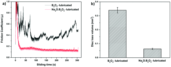 | ||
| Fig. 5 (a) Friction coefficient curves of HSS/SUS316 pair lubricated by B2O3 and Na2O·B2O3 and (b) corresponding wear loss volumes on the disc. | ||
Fig. 6 presents SEM micrographs and the relevant X-ray analysis of the disc worn surfaces lubricated by lone B2O3. The wear track appears broad and deep filled with a number of surficial fractures parallel to the sliding direction. Higher magnification image (Fig. 6b) reveals severe pitting and ploughing while scratching is considered as the most predominant damage. EDS spectrum extracted from inside the wear track reveals no sign of B but only elements associated to steel including Fe, Ni and O. The high intensity of O suggests adverse oxidation that occurred on the rubbing surface exposed to high ambient temperature. Melt elements B and O are detected outside of the worn area while there is no trace of Fe. A careful examination of Fig. 6a points out that the vicinity of the wear track looks vaguely brighter than the contact area due to charging effect of B2O3 whose electronic conductivity is very poor.23 The phenomenon occurs by the accumulation of incident electrons on B2O3 surface which subsequently reflects all the incoming beam and eventually results in visually ambiguous contrast. These observations can be explained by the possibility that B2O3 was unable to withstand the stressed shearing on the contact area and subsequently squeezed out to both sides of the sliding track. As a result, steel tribopairs became fully exposed without lubrication aid so the direct contacts inevitably result in rising friction, excess wear loss and severe worn morphologies.7,21,22 Fig. 7 displays the contact surface of opposing HSS pin lubricated by B2O3. Higher magnification image shows aggregation of smearing glaze which could be formed from the countered surface. Adhesive wear and material transfer are the signature features of coupled steel contact at elevated temperature without lubrication. EDS mapping reveals a heavily-oxidized pin surface without any trace of lubricant melt (Fig. S3†). Lubrication failure of B2O3 is justified by worn surface observation in support to the deficient friction and wear results mentioned earlier. Despite exhibiting liquid-like behavior, B2O3 melt was not able to enter into the sliding interface which could be due to its weak interaction with the mating material.
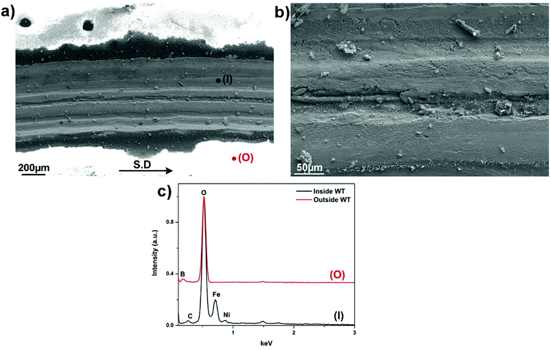 | ||
| Fig. 6 (a) Worn morphologies of SUS316 disc lubricated by B2O3, (b) magnified image of the track and (c) EDS spectrum collected from inside and outside the track. | ||
 | ||
| Fig. 7 (a) Worn morphologies of HSS disc lubricated by B2O3 and (b) higher magnification of the contact inlet zone. | ||
Worn morphologies and according EDS analysis of the steel tribopair lubricated by binary system Na2O–B2O3 are given in Fig. 8. In contrary to what observed in lone B2O3 lubrication, both rubbing surfaces share a common theme of being free from any kind of surficial damages. These infer excellent lubrication efficacy delivered by the addition of Na in the lubricant composition. X-ray spectrum clearly points out chemical footprints of the melt lubricant including B, O and Na alongside a minor trace of Fe on both worn surfaces. The supplement of Na apparently helps anchor the lubricating melt onto the interfaces. At the same time, the element enables the binary system to endure the tribological exposure over the entire sliding duration. This attribute is considered as the most critical foundation for the Na-bearing system to function as an effective lubricant. The interfacial phenomenon is closely related to potential reaction between mating surfaces and the lubricant melt at extreme temperature, which will be discussed further in the following section.
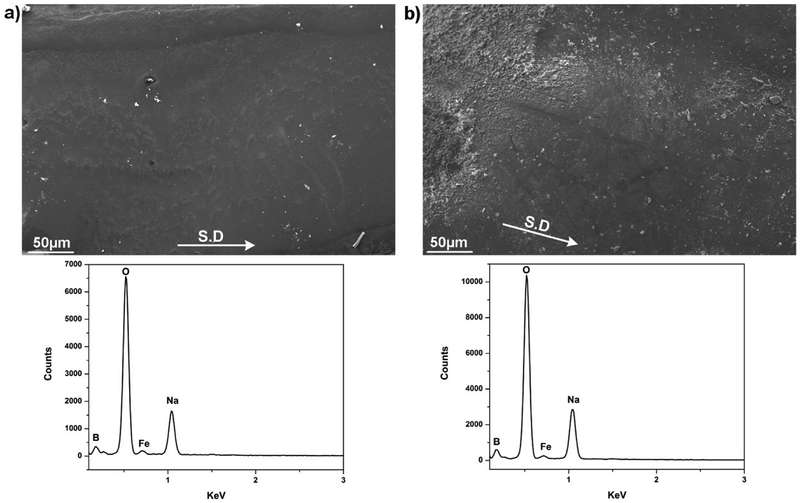 | ||
| Fig. 8 Worn morphologies of steel pair lubricated by binary system Na2O–B2O3 and the corresponding EDS spectrum (a) SUS316 disc, (b) HSS pin. | ||
3.2 Load-carrying capacity of binary system Na2O–B2O3
An array of hot friction test with increasing load was conducted to determine the load-bearing capacity of Na-containing B2O3 melt. Fig. 9 plots the average friction coefficients and disc loss volumes as a function of applying load while other parameters were kept unchanged. It can be expected that both friction and wear loss volumes increase progressively as the loading burden rises. Under 10 N of normal load, friction coefficient was recorded as the lowest value of 0.12 among those tested. Likewise, SUS316 disc yielded the least amount of worn loss volume of 0.063 mm3. As the load elevates, both figures exhibit similar escalating trend. At 30 N, the friction coefficient rises to 0.14 while the worn loss volume nearly doubles compared to what received at 10 N. Under the most severe loading condition (40 N), the Na2O–B2O3 melt seemingly fails to perform as the tribopair generated the highest coefficient of 0.31 which closely approaches the characteristic friction of unlubricated contact.21 Furthermore, the disc wears an approximated amount of 0.3 mm3 which is nearly 3-fold of the 30 N testing point.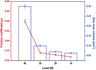 | ||
| Fig. 9 Variation of average friction coefficient and disc loss volume versus increasing load under Na2O–B2O3 lubrication. | ||
Characterization by SEM/EDS on the worn surfaces lubricated by Na2O–B2O3 at 20 N and 30 N was performed and reported in Fig. S4 and S5.† Those worn morphologies display relatively identical features to the one at 10 N with no sign of surface damages while being covered by the lubricant melt.
The sudden disruption in friction/wear behaviors at the highest load 40 N suggests emerging lubrication failure and morphologies examination of the worn pairs was given in Fig. 10 to provide further evidences. It can be recognized that both contact surfaces reveal contrast appearances compared to those under successful lubrication at lower loads. There are signs of scoring damages parallel to sliding direction in conjunction with occasional delamination on the wear track (Fig. 10a). The opposing surface exhibits several types of damage ranging from adhesive wear to plastic smearing (Fig. 10b). The corresponding EDS spectrum suggest heavily oxidized contact areas with the absence of B and insignificant amount of the Na. Fig. 11 captures AFM image of the worn track characterized by nano-grain morphology which is the intrinsic microstructure of freely-grown scale on oxidation-resistant steel.24 This arises from the oxide scale substrate being exposed under excess loading, leaving the contact interfaces unlubricated which consequently leads to increasingly impaired friction and wear properties. As sole B2O3 evidently failed to lubricate at the lightest load concerned, it can be predicted that the corresponding melt is not able to perform under progressively extreme conditions. However, the addition of Na into B2O3 not only radically reverses the lubricity of the beneficiary, but also renders the lubrication sustainability over a wide range of load.
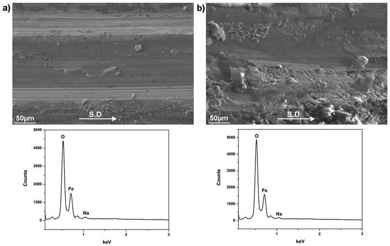 | ||
| Fig. 10 Worn morphologies of steel tribopair lubricated by Na2O–B2O3 at 40 N and the corresponding EDS spectrum (a) SUS316 disc, (b) HSS pin. | ||
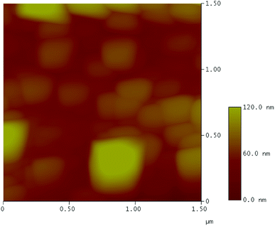 | ||
| Fig. 11 AFM height profile of the wear track after the friction test under Na2O–B2O3 lubrication at 40 N. | ||
3.3 Contact interfaces lubricated by binary system Na2O–B2O3
In order to gain better insights into the mechanism behind the excellent lubrication delivered by the Na addition, microstructural observations and chemical analyses of the rubbing interfaces were provided. The examinations were carried out on both steel tribopairs lubricated at maximum loading capacity of 30 N while the binary system still exhibits desirable friction and wear results.Fig. 12 shows STEM-BF image and relevant EDS extract of the SUS316 disc lubricated by the binary melt Na2O–B2O3. In the BF image (Fig. 12a), there are two distinct regions which can be differentiated by their contrasts. The bright upper layer can be assigned to the lubricant melt while the underlying counterpart featured with characteristic grainy morphology can be designated to the oxide scales. It can be observed that the rubbed oxidized interface is composed entirely of fine grains of oxides whose dimensions vary from 30 to 100 nm. However, visible pores emerging among the grain boundaries imply lacking compactness of the oxide scale. This might arise from the extreme tribological exposure that potentially induces dynamic shearing and shuffling of those individual nano-particles, deformation of the whole oxide scale is therefore inevitable. EDS mapping apparently distinguish the oxide scales from the superimposed lubricant layer. Fe is predominantly present in the oxide substrate while O density appears much higher in the oxidized steel than in the lubricant melt. Na exhibits an interesting distribution pattern as the element highly concentrates on top of the rubbed surface in formation of a continuous film. The representative EDS scan is provided to underline the existence of Na-rich film by the sudden increase in the corresponding signal when it approaches the oxide scale. The thickness of the interfacial film is estimated around ∼50–60 nm. Due to its favorable locality on the sliding interface, the Na film can play a pivotal role in prohibiting immediate asperity contacts, particularly under boundary lubrication regime. In addition, Na is also detected among the grain-boundary voids as indicated by the depletion of Fe and corresponding accumulation of Na, although it looks less dense than the interfacial film. The inward infiltration of Na could be due to the extreme stressed shearing combined with the voids within the oxide microstructure. Apart from the predominant iron oxides, the oxides of Ni and Cr were also formed since the elements are typically included in stainless steel composition for improved oxidation resistance.
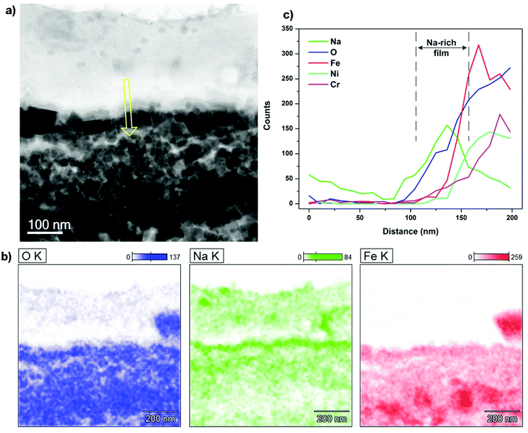 | ||
| Fig. 12 (a) STEM-BF image of contact interface on SUS316 disc lubricated by Na2O–B2O3 at 30 N, (b) EDS mapping and (c) EDS line scan across the interface (yellow arrow indicates scanning direction). | ||
Boron was detected across the interface and its chemical fingerprint was given in the EELS spectrum (Fig. 13). The characteristic excitation edges are located at 195 eV and 204 eV corresponding to the π* and σ* transition, respectively25–27 which indicate the dominant presence of trigonal BO33− species. It is noted that the iron oxide chunk on the right side of EDS mapping is a result of undesired incompatibility between STEM and EDS acquisition system encountered during the microscopy work, however the deviation is very negligible as shown by the consistency of the remaining features.
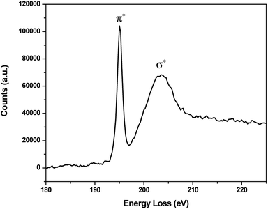 | ||
| Fig. 13 EELS spectrum of B K-edge on the contact interface of SUS316 disc lubricated by Na2O–B2O3 at 30 N. | ||
A similar characterization routine was accomplished on the opposing HSS pin and the outcomes were shown in Fig. 14. The BF image illustrates 2 different regions with varying contrasts, a top transparent layer of lubricant melt residing on the oxide substrate. In addition, there appears a very thin boundary film with a distinct contrast running along the oxide interface. Again, the grain-like morphology of oxidized steel is visible resembling the microstructure of the countered disc surface. However, the scale grown on the contact interface appears tightly compact as the constituting nanoscale grains are organized densely to a degree that excludes any sign of internal porosity. This could be attributed to the superior oxidation resistance and excellent mechanical properties of HSS material. EDS mapping reveals the apparent boundary between the two contacting phases as Fe and O are predominantly found on the oxidized surface while the upper layer contains significant amount of Na. In accordance to the elemental mapping, the interfacial film in BF image turns to be rich in Na with an approximated thickness of ∼50–70 nm. The intrusion of Na appears insignificant which could be alleviated by superior microstructure integrity of the oxide scale. Chemical signature of boron on the interface was detected and presented in the EELS spectrum (Fig. 15) with excitation edges identical to that extracted on the disc interface. The oxide fragments floating in the melt film could be resulted from the wearing process.
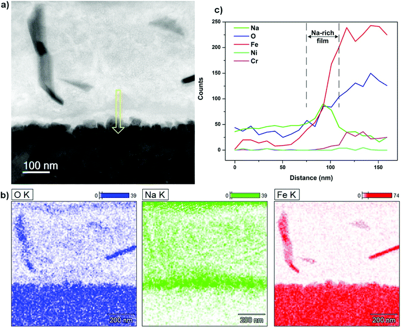 | ||
| Fig. 14 (a) STEM-BF image of contact interface on HSS pin lubricated by Na2O–B2O3 at 30 N, (b) EDS mapping and (c) EDS line scan across the interface (yellow arrow indicates scanning direction). | ||
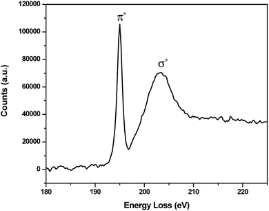 | ||
| Fig. 15 EELS spectrum of B K-edge on the contact interface of HSS pin lubricated by Na2O–B2O3 at 30 N. | ||
TEM image capturing the HSS contact interface on a wider area is given in Fig. 16. Despite having similar contrast with the lubricant layer, Na-rich film can be readily distinguished as a thin continuous layer superimposing on the oxide surface. In addition, it can be observed that the nano-sized grains are rigidly held together with virtually no space among them. Electron Diffractions (ED) of both contacting phases are shown in Fig. 16b and c. The lubricant layer expectedly produces a diffusive ring suggesting amorphous nature of the binary melt while a complex ED pattern was collected on the oxides side which implies the existence of polycrystalline oxides.
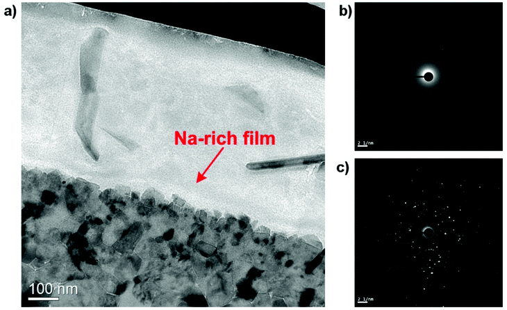 | ||
| Fig. 16 (a) TEM image of the lubricated HSS pin showing the interfacial Na-rich film and electron diffraction of (b) the lubricant film, (c) the oxide scale. | ||
4. Discussions
In high-temperature tribology, the associated heat signifies the complexity of the contact interface by the oxidation of metallic base materials under air atmosphere. Interfacial phenomena become increasingly complicated when lubrication is employed as physico-chemical properties of the lubricating body and potential reactions with mating surfaces deserve considerations. In the present study, HSS pin was used as the countered component against SUS316 disc since the material possesses superior wear resistance which results in a negligible drop in contact pressure over the course of sliding. Under Na2O–B2O3 lubrication, it was shown in Fig. 9 that coefficient tends to increase with rising applied load. The evolution tendency reflects the incurring mixed or boundary lubrication regime which is typically located on the left end of Stribeck curve. A Stribeck curve depicts friction coefficient as a function of testing specifications including sliding velocity, fluid viscosity and pressure.28 It was therefore ensured that the hot friction tests were carried out in such lubrication regimes where physical attributes of the lubricating fluid become less influential on friction and wear behaviors.29 Instead, interfacial occurrences turn out to be a determining factor that directly governs tribological responses of the lubricated contact. It was evident that B2O3 fails to perform as an efficient lubricant manifested by high friction coefficient, excess wear losses and catastrophic surface damages on both steel counterparts. The addition of Na triggers the lubricating capacity of B2O3 as the binary system totally outperforms lone B2O3 with its superior lubrication efficacy. Alongside friction-reducing effect and enhanced wear resistance, the Na-bearing B2O3 has the capacity to preserve its excellent performance over a wide range of extreme loading condition. It is believed that the high temperature chemistry of the concerning binary system has a critical role in its lubrication mechanism.One aspect that makes high temperature tribology distinct from that at lower range is the oxidation of mating surface. High-temperature induces growth of oxide scale which acts as a protective layer against further oxidation.30 Consequently, the contact is exposed between genuine pair of oxide scale whose chemistry states were dramatically altered as the density of O becomes tremendously greater on the sliding surface. In addition, mechanical characteristics and surface microstructure of the developed scale also are also believed to affect the tribological occurrences.
From chemistry view point, the binary oxides Na2O–B2O3 is constituted simultaneously from covalent and ionic bonding. The former one is assigned to the B–O–B framework which determines the polymeric nature while the latter one is associated to the interaction between Na and terminal O. When the temperature reaches the transition point, internal conversion occurs in the form of gradual network collapse and disassociation of ionic moieties. As a result, the binary system becomes a high-temperature ionic liquid composing of cationic Na and depolymerized boron oxide. These behaviors are indicated by increasing conductivity and decreasing viscosity of the melt with rising temperature which have been acknowledged previously.9,10 The addition of Na introduces ionic characteristic into otherwise purely covalent B2O3 melt. With small atomic radius and high mobility, the electrophilic Na cations are heavily attracted by the oxidized steel where electron density is reasonably high due to the presence of O. The strong adsorption of cationic Na renders the binary system a superior affinity towards iron oxide surface than its Na-excluding counterpart. It is exhibited by the formation of continuous Na-rich layers residing on both tribopair interfaces evidenced in Fig. 12 and 14. On one hand, the interfacial reaction can expectedly enhance the wettability of the binary melt on oxidized surface in a similar fashion to hydro bonding on most hydrophilic materials.31,32 On the other hand, the strong ionic bonding helps the Na2O–B2O3 melt sustain the stressed shearing on the interface and subsequently function as an effective lubricant. This is the primary foundation for the excellent lubricating properties including friction reduction, wear resistance and high load-bearing capacity. Under boundary lubrication, direct asperity contacts can be mitigated by the interfacial films which results in enhanced wear resistance and desirably low friction. The extended load-bearing capacity could be attributed to the robustness and resilience of Na thin film. Electrolytic lubricating medium reportedly demonstrates promising performance33–36 and the superficial adsorption is claimed to be the fundamental factor for such behaviors. In addition, some believed that the repulsion between similarly-charged atoms on opposed surfaces can further reduce frictional loss.33
Beside the chemical origin of the lubricant melt, microstructure continuity and mechanical characteristics of the grown scales also exert definite influences on the contact interfaces. It was observed that the mating oxide surfaces are constituted of nano-grains which are well-known for their high toughness strength.37,38 The compactness of the oxide scale plays a key role in preserving the surface integrity under extreme tribological exposure. On the immediate interface of the disc, disintegration of the scale microstructure was shown (Fig. 12) and the shearing-induced disruption results in the voids formation among the individual oxide grains. In addition to the shearing effect, the liquid-like lubricant melt was drawn into these specific sites by intense capillary forces evidenced by the migration of Na into the internal structure of the deformed scale (Fig. S6†). Despite lubrication failure, the intruding action was likely to occur on SUS316 disc surface lubricated at 40 N which generates a minor peak of Na on EDS spectrum from top view analysis (Fig. 10). On the opposing HSS surface, the Na infiltration turns out to be insignificant as the oxide layer shows exceptional coherence. Despite suffering constant pressure, the oxide grown on HSS remains intact and free from deformation (Fig. S7†). This might arise from the inherent properties of multi-alloyed steels since the material chemistry enables strengthened oxidation resistance and mechanical attributes. However, it is also suggested that the friction-reducing effect of the Na2O–B2O3 melt could mitigate the energy dissipation on substrate deformation. Microstructure of the oxide scale also dictates the adsorption manner of Na cation. For instance, a thin layer of Na was observed on oxidized mild-carbon steel with an estimated thickness of ∼20 nm (Fig. 17a) which is less than what achieved on both HSS and SUS316 surfaces (∼50–60 nm). Since mild-carbon steel tends to develop large grains of monocrystalline oxides (Fig. 17b) upon high temperature oxidation,39,40 their specific surface area is reasonably inferior to that derived from oxidized steel with nano-grain morphology. This is equivalent to lesser attractive sites for Na adsorption which leads to the development of thinner and less dense film. In Na2O–B2O3 melt, the Na adsorption supposedly requires a robust platform of oxide scale to function effectively which otherwise might result in possible lubrication failure. The outermost oxide scale on mild-carbon steel is prone to mechanical damage due to its weakly adherent behavior and low strength.41 This possibly contributes to the lubrication failure of Na2O–B2O3 system on HSS/mild-carbon tribopair (Fig. 18).
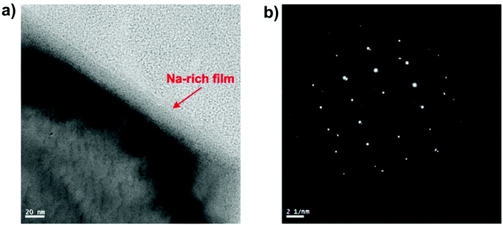 | ||
| Fig. 17 (a) Na nanothin layer adsorbed on oxidized mild-carbon steel, (b) the corresponding electron diffraction pattern indicating monocrystalline structure. | ||
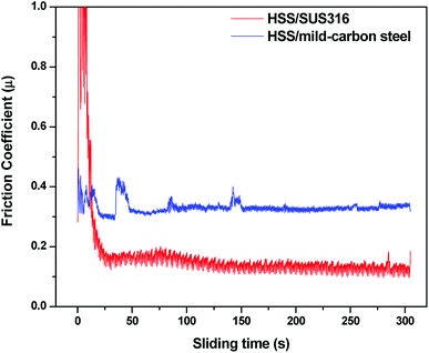 | ||
| Fig. 18 Variation of friction on different mating materials under Na2O–B2O3 lubrication at 10 N, 800 °C. | ||
Apart from lubricating functions, the interfacial Na films can mitigate the oxidation process of the steel surface by obstructing the reaction pathway. Oxidation occurs when the oxidative agents and interstitial Fe ions meet together which results in oxide formation. Under borate lubrication, the reaction probability could be significantly undermined since oxidative species might find it difficult to competitively adsorb on the oxide surface due to the presence of dense layer of Na.
B2O3 singly provides no lubrication effect and this poor behavior could be attributed to its inertness towards iron oxides. Since B2O3 is considered as a weak acid while iron oxides are typically a weak bases on the basis of chemical hardness theory,42 interfacial reaction between those two bodies are unlikely due to unfavorable thermodynamic. However, the role of B2O3 in excellent performance of the binary system cannot be ruled out. As a structural-building compound, boron oxide provides the fundamental platform for viscous shearing characteristic. This ensures fluid lubrication which facilitates the dynamic approach between melt elements and the contact interfaces.
5. Conclusions
The present work aims to refine the role of sodium on the tribological behaviors of binary oxides Na2O–B2O3 on coupling steel pair HSS–SUS316 at 800 °C. By comparing friction and wear behaviors between sole B2O3 and its Na-bearing counterpart, it has been found that the addition of Na arouses the tribological potential of B2O3. The binary system not only provides excellent lubricity and wear inhibition, but also renders extended load-bearing capacity. Interfacial adsorption of Na was proposed to be the driving force of such performances. There are mutual relationships between high temperature, oxidation of steel and physico-chemistry of the lubricant melt that together govern the contact interfaces. Understanding the impact of alkali element can pave a pathway to an advanced formula of lubricant for high temperature applications.Conflicts of interest
The authors declare no conflicts of interest in the present work.Acknowledgements
The study is funded by Australian Research Council Discovery Project (DP) 150103718. The authors acknowledge the use of facilitates and the assistance of Mitchel Nancarrow and David Mitchell in microscopy work at the UOW Electron Microscopy Centre.References
- S. Wan, A. K. Tieu, Y. Xia, H. Zhu, B. H. Tran and S. Cui, Tribol. Int., 2016, 102, 620–635 CrossRef.
- A. K. Tieu, N. Kong, S. Wan, H. Zhu, Q. Zhu, D. R. G. Mitchell and C. Kong, Adv. Mater. Interfaces, 2015, 2, 1–14 Search PubMed.
- S. Wan, A. K. Tieu, Q. Zhu, H. Zhu, S. Cui, D. R. G. Mitchell, C. Kong, B. Cowie, J. A. Denmen and R. Liu, Sci. Rep., 2016, 6, 26008 CrossRef PubMed.
- A. K. Tieu, S. Wan, N. Kong, Q. Zhu and H. Zhu, RSC Adv., 2015, 5, 1796–1800 RSC.
- M. B. Peterson, S. F. Murray and K. Florec, ASLE Technical Publication, 1959, vol. 2, pp. 225–234 Search PubMed.
- F. Sparado, A. Rossi, E. Laine, J. Hartley and N. D. Spencer, Phys. Chem. Glasses: Eur. J. Glass Sci. Technol., Part B, 2016, 57, 233–244 Search PubMed.
- B. H. Tran, A. K. Tieu, S. Wan, H. Zhu, D. R. G. Mitchell and M. J. Nancarrow, J. Phys. Chem. C, 2017, 121, 25092–25103 CrossRef.
- K. Matsumoto, M. Izawa, T. Nakanishi and K. Tsubouchi, Tribol. Trans., 2009, 52, 553–559 CrossRef.
- L. Shartsis, W. Capps and S. Spinner, J. Am. Ceram. Soc., 1953, 36, 319–326 CrossRef.
- J. D. Mackenzie, Chem. Rev., 1956, 56, 455–470 CrossRef.
- C. M. Kuppinger and J. E. Shelby, J. Am. Ceram. Soc., 1985, 68, 463–467 CrossRef.
- S. Gaylord, B. Tincher, L. Petit and K. Richardson, Mater. Res. Bull., 2009, 44, 1031–1035 CrossRef.
- S. Cui, S. Wan, Q. Zhu, A. K. Tieu, H. Zhu, B. C. C. Cowie and L. Wang, J. Phys. Chem. C, 2016, 120, 25742–25751 CrossRef.
- H. M. Le, A. K. Tieu, H. Zhu, D. T. Ta, H. Yu, T. T. H. Ta, V. N. Tran and S. Wan, Phys. Chem. Chem. Phys., 2018, 20, 7819–7835 RSC.
- H. T. T. Ta, A. K. Tieu, H. Zhu, H. Yu, T. D. Ta, S. Wan, N. V. Tran and H. M. Le, J. Phys. Chem. C, 2018, 122, 635–647 CrossRef.
- S. Balc, N. A. Sezgi and E. Eren, Ind. Eng. Chem. Res., 2012, 51, 11091–11096 CrossRef.
- S. Iwadoh and T. Mori, ISIJ Int., 1992, 32, 1131–1140 CrossRef.
- M. Nilsson and M. Olsson, Proc. Inst. Mech. Eng., Part J, 2013, 227, 838–844 Search PubMed.
- F. J. Belzunce, A. Ziadi and C. Rodriguez, Eng. Failure Anal., 2004, 11, 789–797 CrossRef.
- V. Vitry, S. Nardone, J.-P. Breyer, M. Sinnaeve and F. Delaunois, Mater. Des., 2012, 34, 372–378 CrossRef.
- H. Zhu, Q. Zhu, A. K. Tieu, B. Kosasih and C. Kong, Wear, 2013, 302, 1310–1318 CrossRef.
- M. Pellizzari, D. Cescato and M. G. D. Flora, Wear, 2009, 267, 467–475 CrossRef.
- K. H. Kim, Z. Akase, T. Suzuki and D. Shindo, Mater. Trans., 2010, 51, 1080–1083 CrossRef.
- Q. Zhu, H. T. Zhu, A. K. Tieu and C. Kong, Corros. Sci., 2011, 53, 3603–3611 CrossRef.
- G. Yang, G. Mobus and R. J. Hand, Micron, 2006, 37, 433–441 CrossRef PubMed.
- L. A. J. Garvie and A. J. Craven, Am. Mineral., 1995, 80, 1132–1144 Search PubMed.
- S. Cheng, G. Yang, Y. Zhao, M. Peng, J. Skibsted and Y. Yue, Sci. Rep., 2015, 5, 17526 CrossRef PubMed.
- X. Lu, M. M. Khonsari and E. R. Gelinck, J. Tribol., 2006, 128, 789–794 CrossRef.
- J. A. Schey, Tribology in Metalworking: Friction, Lubrication and Wear, American Society for Metals, 1983 Search PubMed.
- R. Y. Chen and W. Y. D. Yuen, Oxid. Met., 2003, 59, 433–468 CrossRef.
- X. Wu, E. Sacher and M. Meunier, J. Appl. Phys., 1999, 86, 1744–1748 CrossRef.
- J. Drelich, E. Chibowski, D. D. Meng and K. Terpilowski, Soft Matter, 2011, 7, 9804–9828 RSC.
- J. Klein, Friction, 2013, 1, 1–23 CrossRef.
- U. Raviv, S. Giasson, N. Kampf, J.-F. Gohy, R. Jerome and J. Klein, Nature, 2003, 425, 163–165 CrossRef PubMed.
- I. Minami, Molecules, 2009, 14, 2286–2305 CrossRef PubMed.
- L. Ma, A. G. -Kipnis, N. Kamps and J. Klein, Nat. Commun., 2015, 6, 1–6 CrossRef PubMed.
- R. Z. Valiev, A. V. Korznikov and R. R. Mulyukov, Mater. Sci. Eng., A, 1993, A168, 141–148 CrossRef.
- J. I. Leinonen, Acta Polytech., 2004, 44, 37–40 Search PubMed.
- C. Juricic, H. Pinto, D. Cardinali, M. Klaus, C. Genzel and A. R. Pyzalla, Oxid. Met., 2010, 73, 115–138 CrossRef.
- W. Sun, A. K. Tieu, Z. Jiang, H. Zhu and C. Lu, J. Mater. Process. Technol., 2004, 155–156, 1300–1306 CrossRef.
- B. Pique, P.-O. Bouchard, P. Montmitonnet and M. Picard, Wear, 2006, 260, 231–242 CrossRef.
- J. M. Martin, T. Onodera, M.-I. D. B. Bouchet, N. Hatakeyama and A. Miyamoto, Tribol. Lett., 2013, 50, 95–104 CrossRef.
Footnote |
| † Electronic supplementary information (ESI) available. See DOI: 10.1039/c8ra04658a |
| This journal is © The Royal Society of Chemistry 2018 |


