
Organic acid assisted one-pot synthesis of highly oriented h-WO3 as an anode material for lithium-ion batteries†
Jiaqin
Yang‡
 *ac,
Can
Guo‡
b,
Jing
Zhang
a and
Lirong
Xu
*a
*ac,
Can
Guo‡
b,
Jing
Zhang
a and
Lirong
Xu
*a
aSchool of Chemistry and Chemical Engineering, Qufu Normal University, Qufu, Shandong 273165, China. E-mail: yjq8681@163.com; xulr2015@qfnu.edu.cn
bSchool of Chemistry and Chemical Engineering, Jiangsu Key Laboratory of Green Synthetic Chemistry for Functional Materials, Jiangsu Normal University, Xuzhou, Jiangsu 221116, China
cKey Laboratory of Advanced Energy Materials Chemistry (Ministry of Education), Nankai University, Tianjin 300071, China
First published on 10th September 2018
Abstract
Hierarchical structures are assembled using various building blocks, which can enhance the features of both micromaterials and nanomaterials. Hierarchical cylindrical and bi-conic h-WO3 architectures were synthesized via the hydrothermal method using organic acids. Both specific architectures were assembled from nanowire bundles with organic acids as bridging molecules, and the formation mechanism was proposed based on experimental observations. With this elaborately designed structure, the electrochemical performance was substantially improved due to the reduced diffusion lengths and enhanced kinetics. When investigated as electrode materials for lithium ion batteries, excellent electrochemical properties were exhibited and a high specific discharge capacity of 704.1 mAh g−1 was maintained after 200 cycles at a current density of 100 mA g−1.
Introduction
The organization of nanostructures by self-assembly is a key challenge in the design of materials with advanced functions. Biomimetic synthesis approaches are particularly promising for the soft-chemistry fabrication of anisotropic materials.1–3 Hydrophilic polymer-controlled morphosynthesis and surfactant-mediated templating techniques are widely exploited in the preparation of inorganic materials as they control the shape and size of semiconductors in aqueous systems.4–8 However, additional surfactants or templates can generate significant impurities in the final product. For this reason, various strategies have been developed to generate well-organized architectures that are controlled solely by the reactants, which also function as bridging molecules. In this case, an interesting situation promptly arises: when the binding affinity of the organic molecules is sufficiently high, the nanocrystal becomes so highly stabilized that crystallographic junctions are formed between the nanocrystal building blocks.Transition metal oxides are regarded as promising anode materials for satisfying the ever-growing demands for high performance lithium ion batteries: higher energy/power densities, improved safety and longer life cycles.9 For example,tungsten trioxide (WO3) has received increasing research attention due to its promising physical and chemical properties for multiple applications, including lithium ion batteries,10–17 supercapacitors,18,19 dye-sensitized solar cells,20 gas sensors,21 photocatalysis,22 electrochromic devices,23 electrocatalysts,24etc.
In this study, we introduce malonic acid (MA) and succinic acid (SA) into the reaction system, which act as the reaction acids and bridging molecules. As a result, we obtain h-WO3 with two novel morphologies of cylindrical and bi-conic architectures via a facile hydrothermal method. Both of the final architectures are assembled from nanowire bundles. The specific hierarchical architectures exhibit favorable electrochemical performance with features of both micromaterials and nanomaterials.
Experimental
Synthesis of hierarchical WO3 architectures
All the chemicals were analytical grade and used without further purification. For the typical synthesis process of cylindrical h-WO3, 1 mmol Na2WO4·2H2O was dissolved in 24 mL of deionized water while stirring, then 10 mmol malonic acid (denoted as MA) was added to the mixture. After stirring for another 10 min, the blended solution was transferred into 33 mL Teflon-lined stainless-steel autoclaves for the hydrothermal reaction at 180 °C for 12 h. Finally, the precipitate was washed several times with deionized water and ethanol and dried at 60 °C for 10 h in vacuum. For the preparation process of bi-conic h-WO3, the acid was changed to succinic acid (denoted as SA) and the amount used was 14 mmol. Other procedures were the same as the above preparation process.Morphological characterization of h-WO3 architectures
The crystalline structures of the prepared samples were characterized by X-ray powder diffraction (XRD) (Rigaku D/Max-2500, Cu Kα radiation, λ = 0.1518 nm). The morphologies were detected by scanning electron microscopy (SEM) using a JEOL JSM-6700F (field emission) scanning electron microscope and transmission electron microscopy (TEM) using a Tecnai G2 F20 TEM.Electrochemical characterization of h-WO3 architectures
The prepared samples were used as anode materials for lithium ion batteries. The anode electrode was fabricated by mixing the active material, acetylene black, and a binder (PVDF) in a weight ratio of 80![[thin space (1/6-em)]](https://www.rsc.org/images/entities/char_2009.gif) :10:10, and then coated on Cu foil. The mass of the active materials in the prepared electrodes was approximately 2 mg. The lithium foil served as a counter and reference electrode. For the electrolyte, 1 mol dm−3 solution of LiPF6 dissolved in ethylene carbonate (EC), ethyl methyl carbonate (EMC), and dimethyl carbonate (DMC) (1:1:1 by volume) was used. The testing cells were assembled in an argon-filled glove box, where water and oxygen concentrations were maintained below 5 ppm. Galvanostatic charge/discharge measurements were performed on a Land CT2001 automatic battery tester in the voltage range of 0.01–3.00 V. Cyclic voltammetry (CV) and electrochemical impedance spectroscopy (EIS) were performed on a CHI660B electrochemical workstation. All tests were performed at room temperature.
:10:10, and then coated on Cu foil. The mass of the active materials in the prepared electrodes was approximately 2 mg. The lithium foil served as a counter and reference electrode. For the electrolyte, 1 mol dm−3 solution of LiPF6 dissolved in ethylene carbonate (EC), ethyl methyl carbonate (EMC), and dimethyl carbonate (DMC) (1:1:1 by volume) was used. The testing cells were assembled in an argon-filled glove box, where water and oxygen concentrations were maintained below 5 ppm. Galvanostatic charge/discharge measurements were performed on a Land CT2001 automatic battery tester in the voltage range of 0.01–3.00 V. Cyclic voltammetry (CV) and electrochemical impedance spectroscopy (EIS) were performed on a CHI660B electrochemical workstation. All tests were performed at room temperature.
Results and discussion
After conducting the reactions under the optimized conditions of 180 °C for 12 h with MA and SA, cylindrical and bi-conic h-WO3 were obtained and are denoted as S-1 and S-2, respectively. The phase and purity of the samples were examined by powder X-ray diffraction (Fig. S1, ESI†), which indicates that all major diffraction peaks are perfectly assigned to the hexagonal structure of WO3 with lattice constants of a = 7.298 and c = 3.899 (JCPDS no. 33-1387, space group: P6/mmm). Strong and sharp diffraction peaks indicate the good crystallinity of the synthesized products. Furthermore, the XPS technique has been conducted to investigate the valence state of the element, and the XPS spectra of S-1 are shown in Fig. 1a–b. The survey spectrum (Fig. 1a) demonstrates that the surface of the sample is composed of tungsten and oxygen. As shown in Fig. 1b, two peaks are mainly observed at 35.67 eV (W 4f7/2) and 37.82 eV (W 4f5/2) in the high-resolution XPS spectrum of W 4f, which indicates that W in S-1 has 6+ oxidation state. In addition, the splitting of 2.13 eV between W 4f7/2 and W 4f5/2 also confirms the 6+ oxidation state of W.25 In addition, EDS measurements and elemental mapping of S-1 and S-2 were performed to demonstrate the purity of the prepared material. As shown in Fig. 1c and S2,† the atomic ratios of W to O for both S-1and S-2 are approximately 1:3. Elemental maps of S-1 (Fig. 1d–f) further demonstrate that W and O have a uniform spatial distribution.
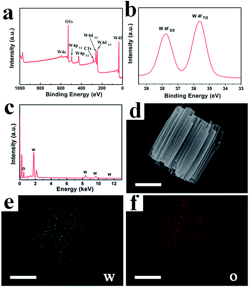 | ||
| Fig. 1 EDS and elemental mapping patterns of S-1, the scale bar in (b) to (d) is 1 μm. | ||
As shown in Fig. 2a, the resulting sample (S-1) with MA as the bridging acid exhibits a highly organized cylindrical architecture with all the nanorods oriented parallel to each other. Furthermore, the low-magnification TEM image in Fig. S3a† corresponds well to the SEM observations. Further magnification of part of the hierarchical structure reveals that each nanorod is assembled from nanowire bundles (Fig. 2b) and the diameter of a single nanowire is approximately 20 nm. In Fig. 2c, the lattice spacing measured by HRTEM is 0.37 nm, which corresponds to the (001) lattice plane. Selected area electron diffraction (SAED) reveals that the nanowires have a single crystal structure and grow along the direction of [001].26 When the organic acid is changed to SA, the sample (S-2) presents a bi-conic hierarchical architecture, accompanied by monodispersed nanorods (Fig. 2d–f and S3b†). The crystal structure comprising nanorod bundles appears wide in the middle and pointed at both ends (Fig. 2e). As shown in Fig. 2f, the lattice spacing measured by HRTEM is 0.38 nm, which suggests a growth direction of [001] (inset in Fig. 2f).
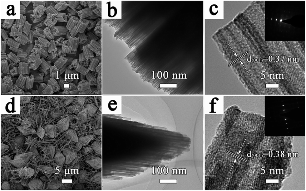 | ||
| Fig. 2 (a and d) Low-magnification SEM images, (b and e) TEM images, and (c and f) HRTEM images (insets are SAED images) of S-1 and S-2. | ||
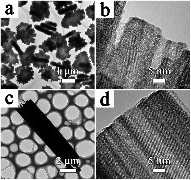
The SEM images in Fig. 3 and 5 reveal the effects of reaction time on the formation of cylindrical and bi-conic architectures. For S-1, the sample initially collected at 1 h (Fig. 3a) shows a disc-like morphology with a diameter of approximately 1.5 μm. The disc-like structure is composed of tiny closely packed nanorods with an identical length of 200 nm. The diffraction peaks in Fig S4† mainly index to WO3 (JCPDS no. 33-1387), besides several impurity peaks at 16°, 26° and 35°. As the reaction time increases to 2 h, 4 h, 8 h, 12 h, and 48 h (Fig. 3b–f), the length of the disc-like structure gradually increases and develops into a tree-stump, then a tree-trunk type structure. Meanwhile, the diameter and packing of the nanorods increases at the macro-level. In addition, the corresponding XRD pattern in Fig. S4† is consistent with the sample collected at 12 h. TEM analysis of the samples collected at 1 h and 48 h is presented in Fig. 4. In Fig. 4a and b, the diameter of the non-compact nanowires collected at 1 h is approximately 15 nm. For the sample collected at 48 h (Fig. 4c and d), crystallographic fusion occurs between adjacent nanowires, resulting in a single nanowire with an increased diameter of up to several nanometers.
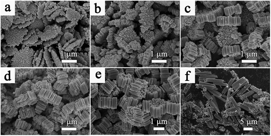 | ||
| Fig. 3 SEM images of the prepared sample with MA collected at different time intervals: (a) 1 h, (b) 2 h, (c) 4 h, (d) 8 h, (e) 12 h, and (f) 48 h. | ||
 | ||
| Fig. 4 TEM and HRTEM images of the prepared sample with MA collected at different time intervals: (a and b) 1 h and (c and d) 48 h. | ||
For S-2, no product forms until the reaction time reaches 4 h and a preliminary bi-conic structure emerges (Fig. 5a). The structure is composed of tiny nanoparticles and is slightly different from that of S-1. After the reaction proceeds for 8 h (Fig. 5b), the nanoparticles act as seeds for further growth. Initially, they grow gradually into nanowires before exhibiting an integrated bi-conic architecture. With further increase of the reaction time to 12 h, the long, rapidly growing nanowires may act as guiding crystals in the center of the bundles and the short nanowires become closely connected parallel to the surface of the guiding nanowires, resulting in bundles of nanowires that are wide in the middle and pointed at both ends. However, the internal stress in the bi-conic structure increases with further growth. Fig. 5c shows a number of dispersed nanorods formed by stress cracking. When the reaction time proceeds to 36 h (Fig. 5d), only uniformly dispersed nanorods are observed. As for the XRD pattern in Fig S5,†all the diffraction peaks can be indexed to WO3 (JCPDSno. 33-1387). In order to illustrate the morphological evolution of S-1 and S-2, a simple schematic diagram is shown in Fig. 6.
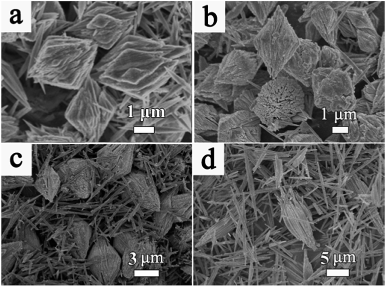 | ||
| Fig. 5 SEM images of the prepared sample with SA collected at different time intervals: (a) 4 h, (b) 8 h, (c) 12 h, and (d) 36 h. | ||
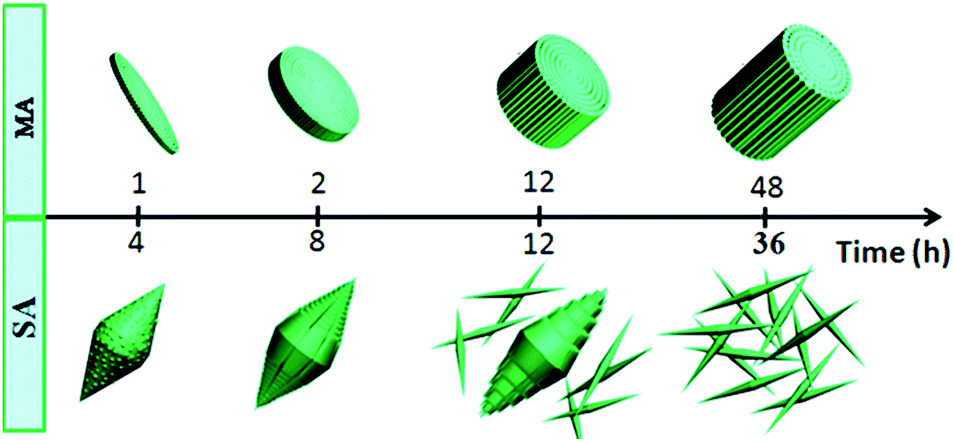 | ||
| Fig. 6 Simple schematic diagram illustrating the morphological evolution of S-1 and S-2. | ||
Highly oriented one-dimensional tungsten oxide nanostructures have previously been prepared by self-assembly using additives such as oxalic acid, deferoxamine, and benzyl alcohol.27–29 In these cases, the nanoparticles are arranged by organic interactions on the interfaces between the building blocks. In addition, the tungsten oxide nanocrystals have high shape anisotropy; thus, assembly can spontaneously occur resulting in the formation of highly organized nanoparticle arrays or well-organized architectures. In our reaction system, both MA and SA include two carboxyl groups; Fig. S6†presents the major fractions in the solution at different pH ranges. At the beginning of the reaction, the solution pH values are 1.92 and 3.03. Therefore, there are a number of single molecules in the reaction system such that the single molecule could drive the assembly by hydrogen bond interactions between the adjacent nanowires. Fig. 7 presents a model of nanowire self-assembly. The organization of the nanowires into bundles is controlled by specific interactions between the organic species and the products. For h-WO3 nanowires, (100) and (010) crystal faces are the main exposed faces. Oxygen atoms on these two faces could interact with one carboxyl group via hydrogen bond interactions. Meanwhile, the other carboxyl group could bond with another newly formed h-WO3 nanowire, finally forming the nanowire bundle structure.
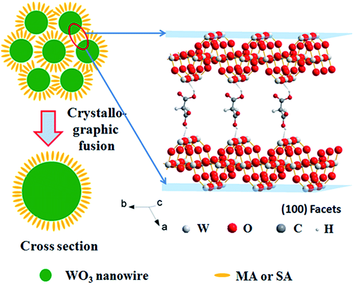 | ||
| Fig. 7 Schematic representation of the stump-like and shuttle-like architectures assembled from nanowire bundles. | ||
The amounts of organic residue in S-1 and S-2 are measured by thermogravimetric analysis (TGA), performed in an air atmosphere from room temperature to 500 °C (Fig. S7†). The small mass loss below 100 °C can be ascribed to the volatilization of absorbed water. The sharp mass loss of 2.70% and 2.92% at 100 °C and 300 °C, respectively, is due to the decomposition of organic residue. Further increase in the temperature to 500 °C or more does not alter the mass.
The electrochemical performances of S-1 and S-2 as anode electrodes were examined for lithium ion batteries. As shown in Fig. S8,† the specific surface areas of S-1 and S-2 are 8.973 and 8.491 m2 g−1, respectively, which were examined using the Brunauer–Emmett–Teller method. As the specific surface area is related to the reactive sites for contact between the electrode and electrolyte, S-1 is anticipated to show better electrochemical properties than S-2. For the h-WO3 electrode materials, the calculated theoretical capacity is 693 mAh g−1. The charge/discharge mechanism is consistent with a conversion reaction mechanism, which can be expressed as:30,31
| WO3 + 6Li+ + 6e−→ W + 3Li2O | (1) |
| W + 3Li2O→WO3+ 6Li++ 6e− | (2) |
Therefore, the charge/discharge capacities are derived from the reversible reaction between the formation of the metal and lithium oxide. As a transition metal oxide, WO3 has received considerable attention as an anode material due to its abundant reserve volume, high theoretical specific capacity, high intrinsic density (>7 g cm−3), rich framework diversity and strong mechanical stability. Furthermore, h-WO3, a stable phase for WO3, is composed of WO6 octahedra but with six- and three-membered rings that share the equatorial oxygen in the ab plane.32 The triangular and hexagonal tunnels are formed by sharing the axial oxygen in the c axis, and the special hexagonal tunnels can benefit the utilization of h-WO3 as the intercalation host to form MxWO3 (M = Li+, Na+, K+, etc.).33–35
Fig. 8a shows the typical galvanostatic charge/discharge curves of S-1 at a current density of 100 mA g−1, the electrochemical reaction with lithium involves multiple decomposition and formation steps in the initial discharge curve. The characteristic plateau near 1 V followed by a sloped decrease in voltage during the first charging process indicates the conversion reaction mechanism.36–39 The subsequent discharge curves show little difference compared to the initial discharge curve, while the charge curve is identical ranging from the first to the last. The observed overpotential between 1 and 1.6 V can be attributed to the kinetic nature of the proposed charging reaction shown in eqn (1). Owing to the slow kinetic nature of the intrinsic properties expressed in eqn (1) and (2), a slow scan rate of 0.2 mV s−1 was adopted for the measurement of CV. As shown in Fig. 8b, the first three CV curves agree well with the initial charge/discharge curves. The reduction peaks located at 0.3 V and 0.7 V correspond to the plateaus of the initial galvanostatic discharge curve, which are irreversible electrochemical processes. However, for the second and third cycles, no peak separation is observed, indicating a fully reversible reaction for subsequent cycles.
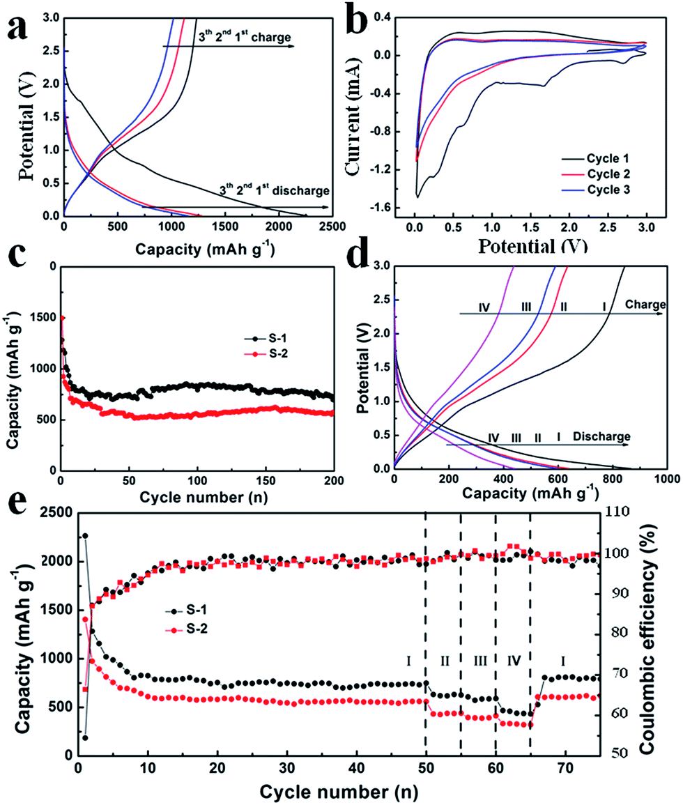 | ||
| Fig. 8 (a) Typical charge/discharge curves and (b) CV curves of the S-1 electrode, (c) the cycling performances of S-1 and S-2 electrodes at a current density of 100 mA g−1, (d) the charge/discharge curves measured at different current densities, (e) rate performances of S-1 and S-2 electrodes. The current densities are 100 mA g−1 (I), 200 mA g−1 (II), 250 mA g−1 (III), and 500 mA g−1 (IV), respectively. | ||
Fig. 8c shows the cycling performance of S-1 and S-2 electrodes at a current density of 100 mA g−1 for 200 cycles. As shown in Fig. 8c, S-1 exhibits an initial specific capacity of 1283.3 mAh g−1 and a reversible specific capacity of 704.1 mAh g−1 after 200 cycles. These values are much higher than those of S-2 (initial specific capacity of 1498.4 mAh g−1 and the reversible specific capacity of 570.3 mAh g−1 after 200 cycles). The better electrochemical performance of S-1 can be attributed to the hierarchical structures, which can fully promote the penetration of the electrolyte and shorten the distance for Li+. In addition, the interconnected nanowires might benefit maintenance of the structural stability of h-WO3 nanowire bundles and provide good electronic contact during the charge and discharge processes. As shown in Fig. S9,† the SEM image of S-1 after 200 cycles shows great structural stability, which well indicates the cycling stability. However, there is large capacity degradation between the initial and subsequent cycles, which is generally due to electrode pulverization, the irreversible electrochemical decomposition of the electrolyte, and the subsequent formation of an SEI layer on the surface.11,40
Fig. 8d and e show the galvanostatic charge/discharge curves and the rate performance of S-1 and S-2, whereby the current densities increase in a stepwise manner (100 mA g−1, 200 mA g−1, 250 mA g−1, 500 mA g−1 and 100 mA g−1). After 50 cycles at the current density of 100 mA g−1, the discharge capacities remain at 749.9 mAh g−1 and 559.9 mAh g−1 for S-1 and S-2 electrodes, respectively. Meanwhile, the calculated coulombic efficiencies of S-1 and S-2 electrodes are constant with cycling, again demonstrating excellent reversibility of the electrodes. Meanwhile, the corresponding rate capacities are 618.0 mAh g−1, 586.5 mAh g−1, 439.3 mAh g−1, and 792.6 mAh g−1 for the S-1 electrode, and 438.3 mAh g−1, 388.6 mAh g−1, 328.8 mAh g−1, and 619.5 mAh g−1 for the S-2 electrode, respectively. These electrochemical performances are excellent compared to those reported in the previous studies.14,15,31 In conclusion, the excellent electrochemical performance of S-1 can be attributed to the following effects: (1) nanowire bundles can provide more active sites for redox reactions; (2) the unique structure can promote the kinetics of lithium ion storage with shortened diffusion paths; (3) the interconnected nanowires can serve as a buffer to accommodate severe changes in volume during lithiation/delithiation processes.18
The electrochemical impedance spectra (EIS) of S-1 and S-2 electrodes (Fig. 9) clearly show a depressed semicircle in the high-frequency range and an angled straight line in the low-frequency range, and the equivalent circuit is shown as an inset.41,42 The constant phase element (Cd) represents the electrical double-layer capacitance of the electrode/solution interface. The diameter of the semicircle represents the interfacial charge transfer resistance (Rct), while the angled straight line (Warburg impedance (Zw)) is related to lithium diffusion resistance. It was noted that S-1 showed a lower Rct (about 306.5 Ω) than S-2 (about 374.9 Ω), suggesting the ultra-fast electron transfer reaction kinetics of S-1. Furthermore, S-1 shows a lower internal resistance (Rs, composed of the electrolyte resistance and the electrode resistance), which can be estimated from the intercept at the X-axis at high frequency. These lower Rct and Rs are beneficial for enhancing the electrochemical performance of S-1.
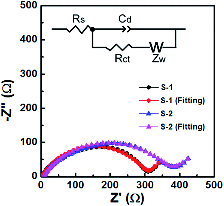 | ||
| Fig. 9 Nyquist plots of the S-1 and S-2 electrodes. The inset shows the equivalent circuit. | ||
Conclusions
In summary, highly organized cylindrical and bi-conic h-WO3 hierarchical structures were prepared via the hydrothermal method using organic acids as bridging molecules. An analysis of their application as electrode materials for lithium ion batteries indicated that the specific hierarchical architectures exhibited good electrochemical properties. These synthesized materials also have potential applications in other fields, such as gas sensors, photo-catalysts, and electrodes in other electronic devices.Conflicts of interest
There are no conflicts to declare.Acknowledgements
This work was supported by the National Natural Science Foundation of China (Grant No. 21505085), the Scientific Research Foundation of Qufu Normal University (xkj201601), and Postgraduate Research & Practice Innovation Program of Jiangsu Province (No. KYCX17_1584).Notes and references
- J. Polleux, N. Pinna, M. Antonietti and M. Niederberger, J. Am. Chem. Soc., 2005, 127, 15595–15601 CrossRef PubMed.
- R.-H. Jin, D.-D. Yao and R. Levi, Chem.–Eur. J., 2014, 20, 7196–7214 CrossRef PubMed.
- L. Ruan, E. Zhu, Y. Chen, Z. Lin, X. Huang, X. Duan and Y. Huang, Angew. Chem., Int. Ed., 2013, 52, 12577–12581 CrossRef PubMed.
- S.-H. Yu and H. Cölfen, J. Mater. Chem., 2004, 14, 2124–2147 RSC.
- Y. Li, W. Luo, N. Qin, J. Dong, J. Wei, W. Li, S. Feng, J. Chen, J. Xu, A. A. Elzatahry, M. H. Es-Saheb, Y. Deng and D. Zhao, Angew. Chem., Int. Ed., 2014, 53, 9035–9040 CrossRef PubMed.
- H. Cölfen and S. Mann, Angew. Chem., Int. Ed., 2003, 42, 2350–2365 CrossRef PubMed.
- S. Furukawa, Y. Takashima, K. Yoshida, S. Isoda and S. Kitagawa, Angew. Chem., Int. Ed., 2009, 48, 4739–4743 CrossRef PubMed.
- J. Zhu, J. Wang, F. Lv, S. Xiao, C. Nuckolls and H. Li, J. Am. Chem. Soc., 2013, 135, 4719–4721 CrossRef PubMed.
- H. Wu, J. Chen, H. Hng and X. Lou, Nanoscale, 2012, 4, 2526–2542 RSC.
- A. Phuruangrat, O. Yayapao, T. Thongtem and S. Thongtem, Russ. J. Phys. Chem. A, 2017, 91, 2441–2447 CrossRef.
- X. Yang, Y. Qi, Y. Liu, Y. Zhou, K. Chen, B. Zhou and W. Chen, J. Electrochem. Soc., 2017, 164, A2783–A2789 CrossRef.
- J. Yang, L. Jiao, Q. Zhao, Q. Wang, H. Gao, Q. Huan, W. Zheng, Y. Wang and H. Yuan, J. Mater. Chem., 2012, 22, 3699–3701 RSC.
- X. Duan, S. Xiao, L. Wang, H. Huang, Y. Liu, Q. Li and T. Wang, Nanoscale, 2015, 7, 2230–2234 RSC.
- K. Bao, W. Mao, G. Liu, L. Ye, H. Xie, S. Ji, D. Wang, C. Chen and Y. Li, Nano Res., 2017, 10, 1903–1911 CrossRef.
- H. Tong, Y. Xu, X. Cheng, X. Zhang, S. Gao, H. Zhao and L. Huo, Electrochim. Acta, 2016, 210, 147–154 CrossRef.
- X. Gu, F. Wu, B. Lei, J. Wang, Z. Chen, K. Xie, Y. Song, D. Sun, L. Sun, H. Zhou and F. Fang, J. Power Sources, 2016, 320, 231–238 CrossRef.
- J. Yang, L. Xu, S. Yan and W. Zheng, RSC Adv., 2016, 6, 18071–18076 RSC.
- X. Wu and S. Yao, Nano Energy, 2017, 42, 143–150 CrossRef.
- C. P. P. Wong, K. M. Lee and C. W. Lai, J. Mater. Sci., 2017, 28, 14554–14567 Search PubMed.
- H. Elbohy, K. M. Reza, S. Abdulkarim and Q. Q. Qiao, Sustainable Energy Fuels, 2018, 2, 403–412 RSC.
- J. Zhang, H. Lu, C. Yan, Z. Yang, G. Zhu, J. Gao, F. Yin and C. Wang, Sens. Actuators, B, 2018, 264, 128–136 CrossRef.
- S. L. Wang, Y. Zhu, X. Luo, Y. Huang, J. Chai, T. I. Wong and G. Q. Xu, Adv. Funct. Mater., 2018, 28, 1705357 CrossRef.
- Y. Wei, M. Chen, W. Liu, L. Li and Y. Yan, Electrochim. Acta, 2017, 247, 107–115 CrossRef.
- Y. Jin, D. Han, W. Jia, F. Li, X. Chen, G. Huang and D. Zhang, Int. J. Electrochem. Sci., 2017, 12, 6535–6544 CrossRef.
- P. A. Shinde, A. C. Lokhande, N. R. Chodankar, A. M. Patil, J. H. Kim and C. D. Lokhande, Electrochim. Acta, 2017, 224, 397–404 CrossRef.
- J. Su, X. Feng, J. D. Sloppy, L. Guo and C. A. Grimes, Nano Lett., 2011, 11, 203–208 CrossRef PubMed.
- Z. Gu, Y. Ma, W. Yang, G. Zhang and J. Yao, Chem. Commun., 2005, 3597–3599 RSC.
- J. Polleux, N. Pinna, M. Antonietti and M. Niederberger, J. Am. Chem. Soc., 2005, 127, 15595–15601 CrossRef PubMed.
- J. Polleux, A. Gurlo, N. Barsan, U. Weimar, M. Antonietti and M. Niederberger, Angew. Chem., Int. Ed., 2006, 45, 261–265 CrossRef PubMed.
- Y. Liu, Y. Jiao, H. Zhou, X. Yu, F. Qu and X. Wu, Nano-Micro Lett., 2015, 7, 12–16 CrossRef.
- A. Inamdar, H. S. Chavan, A. T. A. Ahmed, S. Cho, J. Kim, Y. Jo, S. M. Pawar, Y. Park, H. Kim and H. Im, Mater. Lett., 2018, 215, 233–237 CrossRef.
- K. Huang and Q. Zhang, Nano Energy, 2012, 1, 172–175 CrossRef.
- K. Manthiram and A. P. Alivisatos, J. Am. Chem. Soc., 2012, 134, 3995–3998 CrossRef PubMed.
- L. Gao, X. Wang, Z. Xie, W. Song, L. Wang, X. Wu, F. Qu, D. Chen and G. Shen, J. Mater. Chem. A, 2013, 1, 7167–7173 RSC.
- M. Zheng, H. Tang, Q. Hu, S. Zheng, L. Li, J. Xu and H. Pang, Adv. Funct. Mater., 2018, 28, 1707500–1707526 CrossRef.
- P. Wang, J. Tian, J. Hu, X. Zhou and C. Li, ACS Nano, 2017, 11, 7390–7400 CrossRef PubMed.
- J. Xie, Y. Zhang, Y. Han and C. Li, ACS Nano, 2016, 10, 5304–5313 CrossRef PubMed.
- Y. Lu, Y. Yu and X. W. Lou, Chem, 2018, 4, 972–996 Search PubMed.
- J. S. Chen, Y. L. Cheah, S. Madhavi and X. W. Lou, J. Phys. Chem. C, 2010, 114, 8675–8678 CrossRef.
- C. Jiang, Y. Li, S. Wang, Z. Zhang and Z. Tang, Electrochim. Acta, 2018, 278, 290–301 CrossRef.
- Z. Liu, P. Li, Y. Dong, Q. Wan, F. Zhai, A. A. Volinsky and X. Qu, Appl. Surf. Sci., 2017, 394, 70–77 CrossRef.
- J. Lin, H. Liang, H. Jia, S. Chen, J. Guo, J. Qi, C. Qu, J. Cao, W. Fei and J. Feng, J. Mater. Chem. A, 2017, 5, 24594–24601 RSC.
Footnotes |
| † Electronic supplementary information (ESI) available: Fig. S1–S9. See DOI: 10.1039/c8se00303c |
| ‡ These authors contributed equally to this work and should be considered co-first authors. |
| This journal is © The Royal Society of Chemistry 2018 |