 Open Access Article
Sponge-like N-doped carbon materials with Co-based nanoparticles derived from biomass as highly efficient electrocatalysts for the oxygen reduction reaction in alkaline media†
Guolong Lu *a,
Zhiyuan Lia,
Wenxuan Fana,
Mi Wang*ab,
Shuchen Yangb,
Jiayi Lia,
Zhiyong Changa,
Hang Suna,
Song Liang
 a and
Zhenning Liu*a
aKey Laboratory of Bionic Engineering (Ministry of Education), College of Biological and Agricultural Engineering, Jilin University, Changchun, Jilin Province 130022, P. R. China. E-mail: guolonglu@jlu.edu.cn; Liu_zhenning@jlu.edu.cn
bCollege of Engineering, Changchun Normal University, China. E-mail: wangmi3214@126.com
First published on 8th February 2019
Abstract
The development of highly efficient and low-cost catalysts towards Oxygen Reduction Reaction (ORR) is of significance for renewable energy technologies such as proton-exchange membrane fuel cells and metal–air batteries. This study is to utilize the biomass of soybean straw as the supporting carbon materials to prepare nitrogen and cobalt dual-doped porous biocarbon electrocatalysts (CoNASS) possessing high content of N (1.92%), embedding cobalt nanoparticles and sponge-like structure with high specific surface area (1185.00 m2 g−1) as well as appropriate pore diameter (∼2.17 nm). Meantime, CoNASS exhibits a good electrocatalytic activity with a half-wave potential of 0.786 V (vs. RHE), comparable to a half-wave potential of 0.827 V (vs. RHE) for the commercial Pt/C. The detections of electrochemical kinetics show the electron transfer number of CoNASS is in the range of 3.84–3.92, which indicates 4-electron pathway dominantly occurs in ORR. And the limiting diffusion current density of CoNASS at 1600 rpm is around 5.8 mA cm−2 slightly higher than that of the benchmark Pt/C (5.6 mA cm−2). This work opens a new avenue to utilize soybean straw, one of agriculture waste of large quantity, to prepare high efficient and low-cost catalysts for ORR.
Introduction
The development of efficient, low-cost catalysts for the Oxygen Reduction Reaction (ORR) is very critical to emerging technologies for renewable energy including proton-exchange membrane fuel cells and metal–air batteries.1–4 So far, platinum (Pt) and Pt-based catalysts are still commonly considered to exhibit excellent catalytic activities for ORR.5,6 However, the low abundance and high cost of Pt have limited its application in ORR catalysis.7–10 Consequently, great efforts have been devoted to exploring cost-efficient ORR catalysts as the alternative to Pt-based catalysts. Various ORR electrocatalysts containing heteroatom doped (e.g. Fe, Co, N and S) carbon materials have been extensively investigated and prepared in recent years, where their precursor are heteroatom-doped graphene,11,12 carbon nanotubes,13–15 carbon fibers,16 polymer17,18 as well as metal–organic framework19 as supporting carbon materials (SCM). The performance enhancement of the abovementioned electrocatalysts is usually attributed to the inclusion of Fe or Co nanoparticles as well as N species such as pyridinic N, pyrrolic N, graphitic N and Fe/Co-Nx complex.20–30 Nonetheless, the cost of SCM in these electrocatalysts is still relatively high and limits the practical application.Therefore, it is desirable to develop low-cost SCM, particularly from natural biomass, for the heteroatom doping of ORR electrocatalysts.31–34 More recently, Borghei group has shown that coconut-shell-derived and N-doped carbon materials exhibit high specific surface area (1216 m2 g−1) and good electrocatalytic activities towards ORR, which are comparable or even better than the commercial Pt/C.35 Shao group has reported N, P co-doped porous carbon including LaMnO3 nanoparticles derived from renewable natural okara is capable of excellent ORR catalysis.36 Yet, it is still under extensive research to explore other biomass of large quantity to achieve cheaper ORR electrocatalysts with acceptable performance via a simpler approach.
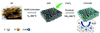
Soybean straws are abundant renewable biomass riched in celluloses, hemicelluloses and lignin37,38 and these contents can contribute to enhancing the activity of ORR catalysts.39,40 To the best of our knowledge, there is no report about a facile method to synthesize ORR catalysts derived from soybean straws. Herein, the electrocatalysts (CoNASS) with N and Co co-doped spongiform porous carbon materials were prepared by a two-step method. The obtained CoNASS has a three-dimensional sponge-like porous structure with a high specific surface area of 1185.00 m2 g−1. More importantly, the CoNASS exhibits an excellent electrocatalytic performance with a 4-electron oxygen reduction mechanism and electrocatalytic activities with ORR peak (0.81 V vs. RHE) in alkaline media which are comparable to those of the commercial Pt/C. The observed electrocatalytic properties of CoNASS can be attributed to the presence of pyridinic N, graphitic N and CoO nanoparticles as well as the interconnected hierarchical porous structure, which synergistically enhance electron transport and oxygen diffusion, then provide more active sites and improve ORR activity.
Experimental section
Catalyst preparation
Scheme 1 shows the process of catalyst synthesis.![[thin space (1/6-em)]](https://www.rsc.org/images/entities/char_2009.gif) :
:![[thin space (1/6-em)]](https://www.rsc.org/images/entities/char_2009.gif) 1, intensely stirred for 12 h until homo-dispersed and oven-dried at 80 °C for 72 h. The obtained uniform mixture was pyrolyzed under N2 flow at a rate of 5 °C min−1 to 800 °C and kept there for 1 h.
1, intensely stirred for 12 h until homo-dispersed and oven-dried at 80 °C for 72 h. The obtained uniform mixture was pyrolyzed under N2 flow at a rate of 5 °C min−1 to 800 °C and kept there for 1 h.Characterization
Scanning electron microscopy (SEM) images were collected on a JEOL JSM-7500F field emission scanning electron microscope (FE-SEM). High-resolution transmission electron microscopy (HRTEM) images were obtained with a JEOL-2010 electron microscope operating at 200 kV. X-ray diffraction (XRD) was performed on a Rigaku X-ray diffractometer (D/max rA) using Cu Kα radiation at a wavelength of 1.542 Å, and the data were collected from 20° to 80°. The nitrogen adsorption–desorption isotherms were obtained on an automated gas sorption analyzer (ASAP 2020M-Physisorption Analyzer) at 77 K. The specific surface area and pore size were calculated by the Brunauer–Emmett–Teller method. Raman spectra were recorded on a laser microscope system (B&W TEK BTC 162E) with an exciting laser of 532 nm. X-ray photoelectron spectroscopy (XPS) was conducted with an ESCALAB 250Xi (Thermo Scientific).Electrochemical measurements
Electrochemical tests were evaluated on the electrochemical workstation (CHI 750E) with three-electrode cell at room temperature. Pt wire, Ag/AgCl and glassy carbon electrode were used as a counter, reference and working electrode, respectively. The working electrode slurry was prepared as follows: 5 mg catalyst and 50 μL Nafion (5 wt%, Dupont) was ultrasonically dispersed in 1 mL isopropanol and further sonicated for 1 h to form a uniform catalyst ink. Then, 15 μL of catalyst ink was deposited onto the surface of rotating ring-disk electrode (RRDE, d = 5.5 mm) and dried in air. The ORR activity was evaluated by cyclic voltammetry (CV) and linear scan voltammetry (LSV) in O2-saturated and Ar-saturated 0.1 M KOH solution with a scan rate of 10 mV s−1. The reversible hydrogen electrode (RHE) was calculated by| VRHE = VAg/AgCl + VAg/AgCl vs. NHE + 0.059pH | (1) |
The transferred electron number (n) of RRDE was expressed by
| n = 4Id/(Id + Ir/N) | (2) |
| % H2O2 = 200Ir/[N(Id + Ir/N)] | (3) |
The transferred electron number (n) of RDE was analyzed by Koutecky–Levich (K–L) equations
| j−1 = jk−1 + jl−1 = (0.035nFACo)−1 + (0.62nFACoD02/3v−1/6ω1/2)−1 | (4) |
Result and discussion
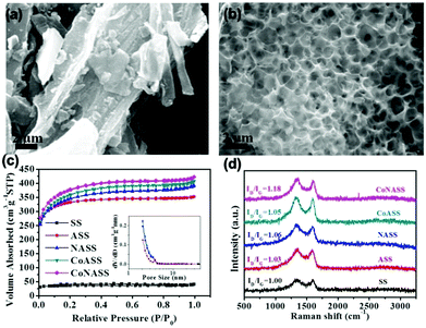
The morphologies of as-prepared catalysts were characterized by SEM (Fig. 1a and b). As shown in Fig. 1a, massive structures with no obvious pores can be found on the SS surface. In contrast, hollow sponge-like structures with abundant macropores (0.5–1.5 μm) evenly distribute in CoNASS (Fig. 1b). Such a porous structure is known as a result of KOH activation during pyrolysis,43 as described by following reactions (5)–(9).| 6KOH + 2C = 2K2CO3 + 2K + 3H2 | (5) |
| K2CO3 = K2O + CO2 | (6) |
| CO2 + C = 2CO | (7) |
| K2CO3 + 2C = 2K + 3CO | (8) |
| C + K2O = 2K + CO | (9) |
Next, nitrogen adsorption–desorption porosimetry was conducted to further examine the porosity and specific surface area of the catalysts. As illustrated in Fig. 1c, the nitrogen adsorption–desorption isotherms (NADIs) of SS, ASS, NASS, CoASS and CoNASS represent type I isotherm with a rapid uptake under low relative pressure and a narrow hysteresis loop. It suggests the existence of numerous pores in ASS, NASS, CoASS and CoNASS, whose specific surface area/pore size is in the order: CoNASS (1185.00 m2 g−1/2.17 nm) > CoASS (1132.95 m2 g−1/2.19 nm) > NASS (1084.86 m2 g−1/2.20 nm) > ASS (1021.40 m2 g−1/2.12 nm), indicating that Co doped, N doped or Co, N dual-doped creates more pores and improves specific surface area, yet has little effects to average pore size. Together with the macropores found in SEM, it is assumed that CoNASS possesses an interconnected hierarchical porous structure, which could promote efficient mass transfer and afford good accessibility to plenty of active sites. However, the specific surface area of SS is as low as 109.81 cm2 g−1, consistent with the morphology observed by SEM (Fig. 1a).
Then, the defect of as-prepared catalysts was conducted by Raman spectra (Fig. 1d). Disordered graphitic carbon and crystalline graphite correspond to the D and G bands around 1350 cm−1 and 1590 cm−1 in Raman spectra, respectively.44,45 Therefore, the ratio of D band to G band (ID/IG) was calculated to evaluate the degree of defect for the pyrolyzed catalysts. The ID/IG ratio of SS (ID/IG = 1.00) is lower than that of ASS (ID/IG = 1.03), NASS (ID/IG = 1.06), CoASS (ID/IG = 1.05) and CoNASS (ID/IG = 1.18). These results suggest that KOH activation, Co doping, N doping or Co, N co-doping causes more defects and disorder of the catalysts, which is in line with the findings from SEM and NADIs.
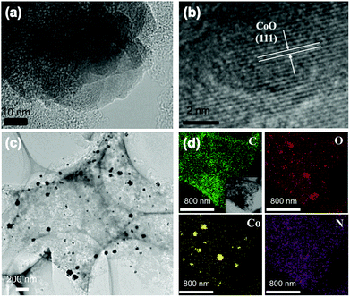
TEM and HRTEM mapping were characterized to reveal the element distribution in the catalyst of CoNASS (Fig. 2). As shown in Fig. S1,† numerous nanoparticles (NPs) exists in CoASS, while no NPs were found in the TEM image of ASS, indicating Co doping could lead to producing nanoparticles after pyrolysis. In CoNASS, abundant NPs with a range size of 20–100 nm were also observed (Fig. 2c and S2†). The NPs in CoNASS were verified by lattice fringe on the HRTEM image, as the d-spacing of 0.245 nm corresponds to the (111) plane of the CoO. Next, XRD was conducted to be further verified the structure of NPs. As shown in Fig. S3,† the diffraction peaks of CoNASS at 36.5°, 42.4°, 61.5° and 73.7° correspond to the (111), (200), (220) and (331) planes of CoO according to the JCPDS No. 43–1004. Meantime, HRTEM element mapping images of CoNASS also show the majority of Co and O element was gathered at same place, while the doped N is evenly distributed on the carbon substrate (Fig. 2c). Together these results indicate that CoO indeed exits in catalysts of CoNASS, which could function to enhance the electron transfer and ORR performance.46,47
To further investigate the contents and chemical states of the elements in the as-prepared carbon samples, XPS was conducted (Fig. S4†). As summarized in Table S1,† C, N and O elements are observed in all samples. The N contents of NASS and CoNASS are 2.13% and 1.92% respectively, due to the post-treatment of chemical impregnation. It suggests the mixing with NH3 can effectively improve the doped N content. The N species in CoNASS catalyst can be corresponding to pyridinic-N (398.2 eV), graphitic-N (401.1 eV), pyrrolic-N (399.7 eV) and oxidized-N (403.2 eV).48,49 As shown in Fig. S4c and Table S1,† the majority of N element in CoNASS is composed of the pyridinic N and graphitic N, as well as pyrrolic N. The pyridinic N could enable adjacent carbon atoms to be active sites for O2 adsorption and ORR initiation.50 The graphitic-N is known as good electron-donor with good charge mobility, which could reinforce the catalytic activity of carbon via electron transfer and improve electrochemical performance.51 The Co content increases from 2.30% in CoASS to 2.71% in CoNASS, which could be due to the synergistic effect of NH3 addition and cobalt ion coordination. Meantime, as shown in Fig. S5,† the C, N and O elements also were observed in the EDS of CoNASS agreed with element mapping and XPS (Fig. 2c and S4†). The inclusion of pyridinic-N and graphitic-N, together with the embedded CoO nanoparticles, could synergistically contribute to the ORR performance of CoNASS.
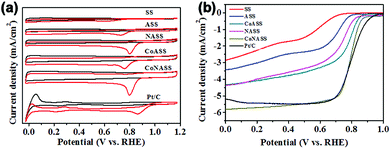
To evaluate the electrocatalytic activity of the catalysts (SS, ASS, NASS, CoASS, CoNASS and Pt/C), we first performed cyclic voltammetric (CV) measurements using rotating disk electrode (RDE) with the potential range from 0.0 to 1.2 V (vs. RHE) in O2- or Ar-saturated 0.1 M KOH solution at a scan rate of 10 mV s−1. As control, 20 wt% Pt/C catalyst was served and compared with as-prepared catalysts, where there is a well-defined cathodic oxygen reduction peak in O2-saturated for all as-prepared electrocatalysts, but not in Ar-saturated electrolytes. Compared with the peak potential 0.61 V of non-activited SS materials, all the activated catalysts show a more positive peak potential at 0.71 V for ASS, 0.80 V for NASS, 0.76 V for CoASS, as well as 0.81 V for CoNASS which is only slighter lower than 0.86 V for Pt/C (Fig. 3a). According to the above electrochemical results, CoNASS (N, Co co-doped) exhibits the most enhanced ORR activity than ASS (only activated), NASS (N-doped), CoASS (Co-doped), which indicates Co, N co-doped carbon materials is an efficient way to improve the activity of ORR catalysts. To gain further insight into the ORR performance of catalysts, linear scan voltammetry (LSV) measurements were conducted at 1600 rpm in O2-saturated 0.1 M KOH solution. As shown in Fig. 3b, the ORR activity of CoNASS with Eonset (onset potential) 0.87 V and E1/2 (half-wave potential) 0.79 V is only slightly lower than that of the commercial Pt/C with Eonset 0.94 V and E1/2 0.83 V, where the electrocatalysis activities of CoNASS are well agreed with that found by CV(Fig. 3a).
In order to quantify the kinetics of the ORR, LSV curves of CoNASS at different rotation speeds from 100 to 2500 rpm in O2-saturated 0.1 M KOH solution were further tested. The LSV curves shown in Fig. 4a exhibit that the limiting current density increases with increasing of rotation speed. Electron transfer number (n: 2-electron or 4-electron), which stands for the generation of H2O or H2O2, is a major factor to evaluate ORR properties.34 The n of CoNASS calculated from the slope of the K–L plots (Fig. 4b) using Koutecky–Levich (K–L) equation (eqn (2)) is 4.03 (Fig. 4c) which is closed to 4.08 for 20 wt% Pt/C (Fig. S6†), indicating the ORR mainly proceeds via a one-step, 4-electron ORR pathway. To verify the n values and peroxide yield, LSV measurements with rotating ring-disk electrode (RRDE) were performed at 1600 rpm in O2-saturated 0.1 M KOH and the corresponding n values and peroxide yields were calculated according to eqn (2) and (3) (Fig. 4d). As shown in Fig. 4d–f, 4-electron reaction dominates catalysis by CoNASS (average n = 3.75) with low production of H2O2 (less than 12.14%), while Pt/C also exhibit a 4-electron pathway (average n = 3.95) with the production of H2O2 (around 5.3%), which is consistent with the results from K–L plots. These results clearly demonstrate a major four-electron transfer pathway for CoNASS as similar as that for commercial Pt/C in alkaline media.
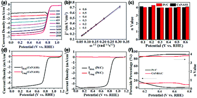 | ||
| Fig. 4 The LSV curves of CoNASS at the rotation speeds of 100, 225, 400, 625, 900, 1225, 1600, 2025 and 2500 rpm (a) obtained from RDE measurements. The corresponding Koutecky–Levich (K–L) plots (b) and electron transfer numbers (n) of CoNASS and Pt/C (c). The LSV curves of CoNASS and Pt/C in 0.1 M KOH solution at 1600 rpm (d and e) respectively obtained from RRDE measurements. The H2O2 yield and n value of CoNASS and Pt/C calculated with eqn (2) and (3) (f). | ||
Conclusions
In summary, N and Co dual-doped catalyst (CoNASS) utilizing biomass, i.e. soybean straw, as supporting carbon material was prepared, characterized and tested in alkaline media as electrocatalysts towards ORR. The electrocatalyst of CoNASS possesses an interconnected hierarchical porous structure with a high specific surface area and contains catalytically active pyridinic N and graphitic N as well as encapsulated CoO nanoparticles. Meantime, CoNASS shows more excellent ORR activities in alkaline media than that of SS (non-activation), ASS (activation), NASS (only N doped), CoASS (only Co doped), even exhibits comparable ORR activities to commercial Pt/C. The work opens a new avenue to utilize biomass to prepare high efficient and low-cost ORR electrocatalysts as an alternative to replace commercial Pt/C for potential renewable energy technologies, such as metal–air batteries and fuel cells.Conflicts of interest
There are no conflicts of interest to declare.Acknowledgements
This work was supported by the National Natural Science Foundation of China (51605188, 51605187, 51607010 and 21673098), Department of Education of Jilin Province (JJKH20180093KJ, JJKH20181163KJ and JJKH20180160KJ), Program for JLU Science and Technology Innovative Research Team and The Joint Program of Jilin Province and JLU (SXGJQY2017-1 and SXGJSF2017-2), Key Scientific & Technological Research & Development Projects in Jilin Province (Grant No. 20180201038GX), Jilin Province Development and Reform Commission (Grant No. 2016C029).References
- C. D. Liu, G. L. Li, G. C. Cheng, C. Hao, S. M. Chen and Y. Y. Xie, RSC Adv., 2016, 6, 73581–73588 RSC.
- K. Surya, M. S. Michael and S. R. S. Prabaharan, Solid State Ionics, 2018, 317, 89–96 CrossRef CAS.
- A. L. Zhu, D. P. Wilkinson, X. E. Zhang, Y. L. Xing, A. G. Rozhin and S. A. Kulinich, Journal of Energy Storage, 2016, 8, 35–50 CrossRef.
- P. Tan, B. Chen, H. R. Xu, H. C. Zhang, W. Z. Cai, M. Ni, M. L. Liu and Z. P. Shao, Energy Environ. Sci., 2017, 10, 2056–2080 RSC.
- B. Fang, J. H. Kim, M. S. Kim and J. S. Yu, Acc. Chem. Res., 2013, 46, 1397–1406 CrossRef CAS PubMed.
- B. Fang, N. K. Chaudhari, M. S. Kim, J. H. Kim and J. S. Yu, J. Am. Chem. Soc., 2009, 131, 15330–15338 CrossRef CAS PubMed.
- Y. J. Wang, W. Y. Long, L. L. Wang, R. S. Yuan, A. Ignaszak, B. Z. Fang and D. P. Wilkinson, Energy Environ. Sci., 2018, 11, 258–275 RSC.
- S. L. You, P. Luo, L. Fang, J. J. Gao, L. Liu, H. T. Xu, H. J. Zhang and Y. Wang, Electrochim. Acta, 2019, 294, 406–412 CrossRef CAS.
- Y. J. Wang, N. N. Zhao, B. Z. Fang, H. Li, X. T. T. Bi and H. J. Wang, Chem. Rev., 2015, 115, 3433–3467 CrossRef CAS PubMed.
- Y. J. Wang, B. Z. Fang, H. Li, X. T. T. Bi and H. J. Wang, Prog. Mater. Sci., 2016, 82, 445–498 CrossRef CAS.
- W. M. Wu, J. G. Leng, H. L. Mei and S. B. Yang, J. Colloid Interface Sci., 2018, 521, 11–16 CrossRef CAS PubMed.
- W. Q. Kong, K. K. Yao, X. D. Duan, Z. G. Liu and J. W. Hu, Electrochim. Acta, 2018, 269, 544–552 CrossRef CAS.
- J. C. Li, P. X. Hou and C. Liu, Small, 2017, 13, 1702002 CrossRef PubMed.
- R. Li, X. Z. Wang, Y. F. Dong, X. Pan, X. G. Liu, Z. B. Zhao and J. S. Qiu, Carbon, 2018, 132, 580–588 CrossRef CAS.
- T. T. Zhao, S. Gadipelli, G. J. He, M. J. Ward, D. Do, P. Zhang and Z. X. Guo, Chemsuschem, 2018, 11, 1295–1304 CrossRef CAS PubMed.
- J. L. Ma, F. L. Meng, D. Xu and X. B. Zhang, Energy Storage Materials, 2017, 6, 1–8 CrossRef.
- G. L. Lu, Y. L. Zhu, K. L. Xu, Y. H. Jin, Z. J. Ren, Z. N. Liu and W. Zhang, Nanoscale, 2015, 7, 18271–18277 RSC.
- G. L. Lu, H. S. Yang, Y. L. Zhu, T. Huggins, Z. J. Ren, Z. N. Liu and W. Zhang, J. Mater. Chem. A, 2015, 3, 4954–4959 RSC.
- J. Ying, J. Li, G. P. Jiang, Z. P. Cano, Z. Ma, C. Zhong, D. Su and Z. W. Chen, Appl. Catal., B, 2018, 225, 496–503 CrossRef CAS.
- M. J. Liu and J. H. Li, ACS Appl. Mater. Interfaces, 2016, 8, 2158–2165 CrossRef CAS PubMed.
- C. Wu, Y. H. Zhang, D. Dong, H. M. Xie and J. H. Li, Nanoscale, 2017, 9, 12432–12440 RSC.
- J. H. Shen, L. Meng, Y. Y. Liu, C. Chen, Y. H. Zhu and C. Z. Li, RSC Adv., 2018, 8, 22193–22198 RSC.
- P. P. Gao, M. Sun, X. B. Wu, S. Z. Zhou, X. T. Deng, Z. Y. Xie, L. Xiao, L. H. Jiang and Q. Z. Huang, RSC Adv., 2018, 8, 26934–26937 RSC.
- S. Yasuda, Y. Uchibori, M. Wakeshima, Y. Hinatsu, H. Ogawa, M. Yano and H. Asaoka, RSC Adv., 2018, 8, 37600–37605 RSC.
- H. Liu, M. Q. Wang, Z. Y. Chen, H. Chen, M. W. Xu and S. J. Bao, Dalton Trans., 2017, 46, 15646–15650 RSC.
- Q. J. Niu, J. X. Guo, Y. H. Tang, X. D. Guo, J. Nie and G. P. Ma, Electrochim. Acta, 2017, 255, 72–82 CrossRef CAS.
- J. C. Carrillo-Rodriguez, I. L. Alonso-Lemus, A. A. Siller-Ceniceros, E. Martinez, P. Piza-Ruiz, G. Vargas-Gutierrez and F. J. Rodriguez-Varela, Int. J. Hydrogen Energy, 2017, 42, 30383–30388 CrossRef CAS.
- Y. J. Wang, B. Z. Fang, X. M. Wang, A. Ignaszak, Y. Y. Liu, A. J. Li, L. Zhang and J. J. Zhang, Prog. Mater. Sci., 2018, 98, 108–167 CrossRef CAS.
- M. Sun, D. Davenport, H. J. Liu, J. H. Qu, M. Elimelech and J. H. Li, J. Mater. Chem. A, 2018, 6, 2527–2539 RSC.
- G. Zhang, G. C. Wang, H. J. Liu, J. H. Qu and J. H. Li, Nano Energy, 2018, 43, 359–367 CrossRef CAS.
- H. Feng, H. Hu, H. Dong, Y. Xiao, Y. Cai, B. Lei, Y. Liu and M. Zheng, J. Power Sources, 2016, 302, 164–173 CrossRef CAS.
- M. Chen, S. Jiang, C. Huang, X. Wang, S. Cai, K. Xiang, Y. Zhang and J. Xue, Chemsuschem, 2017, 10, 1803–1812 CrossRef CAS PubMed.
- M. Zhang, X. Jin, L. Wang, M. Sun, Y. Tang, Y. Chen, Y. Sun, X. Yang and P. Wan, Appl. Surf. Sci., 2017, 411, 251–260 CrossRef CAS.
- Y. Lu, N. Zhu, F. Yin, T. Yang, P. Wu, Z. Dang, M. Liu and X. Wei, Biosens. Bioelectron., 2017, 98, 350 CrossRef CAS PubMed.
- M. Borghei, N. Laocharoen, E. Kibena-Poldsepp, L. S. Johansson, J. Campbell, E. Kauppinen, K. Tammeveski and O. J. Rojas, Appl. Catal., B, 2017, 204, 394–402 CrossRef CAS.
- J. Hu, Z. W. Shi, C. Su, B. Q. Lu, Z. P. Shao and H. Huang, Electrochim. Acta, 2018, 274, 40–48 CrossRef CAS.
- M. Martelli-Tosi, O. B. G. Assis, N. C. Silva, B. S. Esposto, M. A. Martins and D. R. Tapia-Blácido, Carbohydr. Polym., 2017, 157, 512–520 CrossRef CAS PubMed.
- M. Martelli-Tosi, M. d. S. Torricillas, M. A. Martins, O. Benedito Garrido de Assis and D. Rita Tapia-Blácido, J. Nanomater., 2016, 2016, 10 Search PubMed.
- B. Yao, P. Kolla, R. Koodali, Y. C. Ding, S. Balaranjan, S. Shrestha and A. Smirnova, New J. Chem., 2017, 41, 958–964 RSC.
- Y. Lu, G. C. Ye, X. L. She, S. Q. Wang, D. J. Yang and Y. F. Yin, ACS Sustainable Chem. Eng., 2017, 5, 8729–8737 CrossRef CAS.
- F. P. Hu, X. G. Zhang, X. Fang and J. Zhang, Carbon, 2005, 43, 2931–2936 CrossRef CAS.
- Z. Kačarević-Popović, Energy, 2016, 101, 79–90 CrossRef.
- J. C. Wang and S. Kaskel, J. Mater. Chem., 2012, 22, 23710–23725 RSC.
- H. N. Yang, D. C. Lee, K. W. Park and W. J. Kim, Energy, 2015, 89, 500–510 CrossRef CAS.
- Q. H. Wei, H. L. Fan, F. F. Qin, Q. X. Ma and W. Z. Shen, Carbon, 2018, 133, 6–13 CrossRef CAS.
- G. H. Wang, Y. J. Deng, J. N. Yu, L. Zheng, L. Du, H. Y. Song and S. J. Liao, ACS Appl. Mater. Interfaces, 2017, 9, 32168–32178 CrossRef CAS PubMed.
- X. L. Zhang, J. G. Lin, S. M. Chen, J. Yang, L. Song, X. J. Wu and H. X. Xu, ACS Appl. Mater. Interfaces, 2017, 9, 38499–38506 CrossRef CAS PubMed.
- Y. Chang, C. H. Yuan, C. Liu, J. Mao, Y. T. Li, H. Y. Wu, Y. Z. Wu, Y. T. Xu, B. R. Zeng and L. Z. Dai, J. Power Sources, 2017, 365, 354–361 CrossRef CAS.
- C. Hu, Y. Zhou, R. G. Ma, Q. Liu and J. C. Wang, J. Power Sources, 2017, 345, 120–130 CrossRef CAS.
- D. H. Guo, R. Shibuya, C. Akiba, S. Saji, T. Kondo and J. Nakamura, Science, 2016, 351, 361–365 CrossRef CAS PubMed.
- Y. J. Li, G. L. Wang, T. Wei, Z. J. Fan and P. Yan, Nano Energy, 2016, 19, 165–175 CrossRef CAS.
Footnote |
| † Electronic supplementary information (ESI) available. See DOI: 10.1039/c8ra10462j |
| This journal is © The Royal Society of Chemistry 2019 |

