 Open Access Article
Influence of Cl− ions on anodic polarization behaviour of API X80 steel in high potential/current density conditions in Na2SO4 solution
Runzhi Qin ,
Yanxia Du*,
Zhenchang Xu and
Minxu Lu
Institute for Advanced Materials and Technology, University of Science and Technology Beijing, No. 30 Xueyuan Road, Haidian District, Beijing, 100083, China. E-mail: duyanxia@ustb.edu.cn
First published on 8th March 2019
Abstract
Pipeline steel has considerable risk of corrosion in the high voltage direct current interference cases. Thus, under high potential/current density conditions, the anodic polarization behaviour of X80 steel in Na2SO4 solution and the influence of Cl− ions were investigated using reversed potentiodynamic polarization, the current interrupt method, galvanostatic polarization, scanning electron microscopy, and X-ray photoelectron spectroscopy. In the Na2SO4 solution free of Cl− ions, steel was passivated above 0.120 A cm−2 and the potential increased from −0.32 V to 1.43 V. The passive film was composed of Fe3O4, γ-Fe2O3, and FeOOH. The addition of Cl− ions observably influenced the passivation by attacking the passivate film. Low concentration of Cl− ions (<5 mg L−1 NaCl) could set higher demands of current density to achieve passivation and increase the requirement of potential to maintain passivation. A high concentration of Cl− ions (>5 mg L−1 NaCl) completely prevented passivation, showing strong corrosiveness. Thus, the X80 steel was corroded even under high-current-density conditions. The corrosion products were mainly composed of Fe3O4, α-Fe2O3, and FeOOH.
1. Introduction
The high voltage direct current (HVDC) transmission system is undergoing large-scale construction in China. It is going to be an important part in the plan of the national power grid. In monopolar configuration, it injects a large amount of direct current into the soil and introduces stray current interference to nearby pipelines.1,2 In some HVDC interference cases,3 the pipe-to-soil potential was reported to be hundreds of volts, and the highest leakage current density of the coupon was 0.049 A cm−2. At such high voltage and current density conditions, the pipeline steel is at a large risk of corrosion. However, there is no literature report on the corrosion evaluation and mechanism up to now because such a corrosion issue has been newly found. Therefore, the anodic behaviour and the corrosion mechanism of steel require further study.Generally, considerable attention is focused on the corrosion issues in open circuit potentials or in low potential/current density conditions. The traditional test range is always below ∼1 VSCE or ∼0.010 A cm−2. Carbon steel always gets corroded in most soil environments or simulation solutions, where SO42− and Cl− ions always exist.4,5 The Na2SO4 solution is extensively used as a typical simulation solution because SO42− ions are extensively distributed in soil. In Na2SO4 solutions, the anodic polarization behaviour of carbon steel has been extensively studied.6–9 In the traditional test range, steel is corroded without any passivation, and the polarization curves show a typical active dissolution characteristic. For other solutions, the addition of SO42− ions can accelerate the corrosion of steel by changing the composition of products and promoting anodic dissolution.10,11 Even in passivation environments, SO42− ions can attack the passive film and reduce its protectiveness.12 Thus, SO42− ions are considered to be corrosive.
The Cl− ions are considered to be more aggressive.13,14 For passivation environments, Cl− ions weaken the passivation and reduce the protectiveness of carbon steel.15,16 In alkaline solutions, Cl− ions can cause pitting corrosion of carbon steel.17–19 The reversed potentiodynamic (RPD) polarization test is often employed to distinguish passivation with and without pitting. Once pitting occurs, the backward curve cannot overlap with the forward curve, thus forming a hysteresis loop.20–24 Even for stainless steel, Cl− ions can degrade the passive film and introduce pitting.25,26 The mechanism of passivation and the influence of Cl− ions have been extensively studied. Some researchers believe that Cl− ions facilitate the dissolution of a passivate film27 and change its components.28,29 Others declared that the film is attacked through paths that are between nanocrystals and amorphous products.30 Based on the point defect model (PDM) theory,31 it is also suggested that Cl− ions can be adsorbed at the film/solution interface and then react with oxygen vacancies through the Mott–Schottky pair reactions, leading to excessive vacancies at the metal/film interface and thinning of the protective film.15,32,33 Moreover, these results are obtained in the traditional test ranges. However, the effects of Cl− ions in high voltage/current density conditions are still unknown.
As mentioned above, the test ranges reported in the existing literatures are too narrow to meet the high voltage/current density conditions of HVDC interference. For such conditions, we studied the anodic polarization behaviour of X80 steel and the influence of Cl− ions. When the anodic polarization potential/current density was high, steel showed a completely different characteristic from corrosion. The anodic polarization process was analysed and a mechanism model was proposed. Our results will help better understand the dissolution, passivation and de-passivation of steel. Our work can provide a reference to the corrosion evaluation of steel in highly anodic polarization conditions.
2. Experimental procedures
2.1 Materials and solution
The test material was API X80 steel. The chemical constitution in weight percentage (wt%) was 0.07 C, 0.21 Si, 1.61 Mn, 0.12 Ni, 0.14 Cu, 0.041 Nb, 0.012 Ti, 0.0025 S, 0.0081 P, 0.13 Mo, and Fe balance. The specimen was embedded in an epoxy resin with a presented working area of 1 cm−2. Before each experiment, the working electrode surface was polished with 360, 600, 800, and 1000 grit silicon carbide emery papers and ultrasonically cleaned with acetone, ethyl alcohol, and deionized water and then dried under a cold dry wind.The blank test solution was Na2SO4 (4 g L−1), which was made from analytical-grade reagents and deionized water. Then, different amounts of NaCl were added to the blank solution. The concentrations of NaCl were 1, 2, 3, 5, 10, and 50 mg L−1.
All tests were performed at room temperature of 25 ± 2 °C and relative humidity of 30 ± 2%.
2.2 Reversed potentiodynamic polarization measurement and the current interrupt method
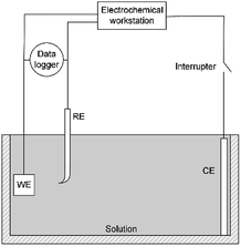
A three-electrode system was used for electrochemical experiments, as shown in Fig. 1. The X80 steel coupons, a Pt electrode, and a saturated calomel electrode (SCE) were used as the working electrode (WE), the counter electrode (CE), and the reference electrode (RE), respectively. All electrochemical potentials were expressed with respect to SCE. An electrochemical workstation (Gamry Reference 3000) was used for electrochemical measurements. When the open-circuit potential (OCP) of WE was stable, the RPD polarization curve was measured from OCP to +6 V and then from +6 V to −1 V. The scanning rate was 1 mV s−1.As the apparent potential contains some IR drop, which is a big error in high potential/current density conditions,34 the current interrupt method was used to eliminate the IR drop and obtain the polarization potential. An interrupter was installed in the CE branch and a 1000 Hz datalogger (Tinker & Rasor, DL-1) was employed to record the potential-time transient during the interruption. When the current was interrupted, the measured potential E(t) exponentially decayed with time:35
 | (1) |
Here, Ep is the polarization potential, E0 is the eventual potential after infinite time, and τ is the time constant. The potential-time transient at each interruption was recorded. Then, the exponential curve was fitted for each transient and Ep was calculated.
2.3 Product characterization
To characterize the product, galvanostatic polarization measurements were obtained. The samples were polarized in 0.120 A cm−2 for 30 min in different solutions. After that, the sample surfaces were rinsed with deionized water and dried with a cold wind. Then, the surface micro-morphologies were observed by scanning electron microscopy (SEM, LEO-1450). The product composition was investigated by X-ray photoelectron spectroscopy (XPS, Kratos AXIS ULTRADLD).3. Results
3.1 Polarization results of apparent potential
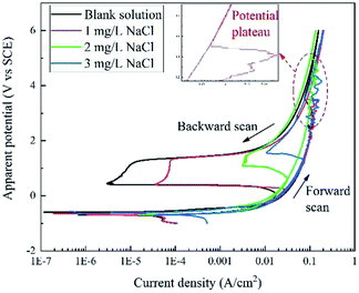
Fig. 2 displays the apparent RPD curves of X80 steel in Na2SO4 solutions with 0, 1, 2, and 3 mg L−1 NaCl. It should be noted that these potentials are apparent potentials, which involve a certain part of IR drop. The test range considerably broadened compared to the traditional one.In the forward scan, the curves show a typical dissolution characteristic in low potential/current density ranges according to the literature.6–9 Out of the traditional range, in particular, there is a potential plateau above ∼2 V or ∼0.1 A cm−2 for each curve, where the current density abnormally decreases with the increase in the potential. After the plateau, the current density increases continuously with the apparent potential. In our experiment, black products were generated at the sample surface before the plateau and then dropped off after the plateau with massive bubbles gushing from the sample surface.
In the backward scan, the curves are similar to the traditional passivation curves. The current density decreased with decline in the apparent potential. A potential drop started form ∼1.4 V at a low current density for each curve, and the current density reached a minimum value at the end of the potential drop. Then, the second potential plateau occurred, at which the current density increased rapidly. After that, the current density decreased with the potential in the similar path of the forward scan until the end of the test. In the experiment, bubbles diminished and finally disappeared after the potential drop.
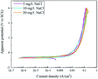
Fig. 3 displays the RPD curves of X80 steel in Na2SO4 solutions with 5, 10, and 50 mg L−1 NaCl. All the curves are very similar with almost the same shape in the forward and backward scans. In our experiment, the samples were corroded all the time and black rust was generated at the sample surface. No gas bubbles were observed.
3.2 Polarization results with IR drop elimination
Based on the current interrupt method, the “real” polarization curves are shown in Fig. 4. The word “real” indicates that these curves are free of IR drop and they are more accurate than the apparent potential curves in Fig. 2 and 3.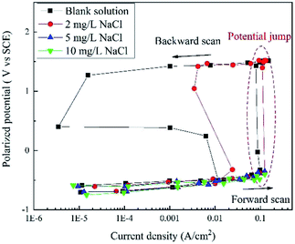 | ||
| Fig. 4 RPD polarization curves of X80 steel in Na2SO4 solutions with 0, 2, 5, 10, and 50 mg L−1 NaCl after IR drop elimination. | ||
When the concentration of NaCl was below 5 mg L−1, the potential plateau was replaced by a potential jump, indicating new electrochemical reactions and mechanisms. Before the potential jump, the curves obeyed the Tafel equation. Then, the polarization potential increased from ∼−0.32 V to ∼1.43 V in the potential jump, while the current density decreased. The sudden increase in the potential is a sign of new electrochemical reactions. At the end of the forward scan, the potential increased to more than 1.50 V. In the backward scan, the potential decreased to a slight extent with a significant decline in the current density until the potential drop. The current density reached a minimum value at the end of the potential drop. Then, a second potential plateau occurred, where the current density increased greatly. The residual part of the curve is very similar to that of the forward scan.
When the concentration of NaCl was higher than 5 mg L−1, there was no potential jump, plateau or drop. The curve shapes were similar for both forward and backward scans. The curves almost overlapped with those measured at a lower NaCl concentration, indicating a similar electrochemical process.
3.3 Product characterization
In each RPD curve, the highest apparent potential was 6 V and the corresponding current density was ∼0.120 A cm−2, which is shown by the red star in Fig. 2 and 3. Thus, to further study the anodic behavior of steel and the influence of Cl− ions on the electrochemical process, the galvanostatic polarization of 0.120 A cm−2 for 30 min was applied to X80 steel samples in different solutions.In the blank solution and that containing 2 mg L−1 NaCl, the sample surfaces remained uncorroded and some gas bubbles were produced, as shown in Fig. 5. The gas was detected to be O2 because of its combustion-supporting characteristic. In solutions with 5 and 10 mg L−1 NaCl, black rust was generated on the sample surface. No gas evolution occurred.
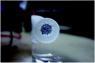 | ||
| Fig. 5 Oxygen evolution on the sample surface during the galvanostatic polarization test in blank solution. | ||
After galvanostatic polarization, the micro-morphologies of the sample surface are presented in Fig. 6. In the blank solution and the solution with 2 mg L−1 NaCl, the samples were not corroded at all, and the scratch in the sample preparation process could be observed. This indicated that the products are thin, neat, and strongly protective in high-current-density conditions. In solutions containing 5 and 10 mg L−1 NaCl, the samples were covered by flake-shaped corrosion products with cracks. Such rust was loose in texture, showing a low protective effect.36
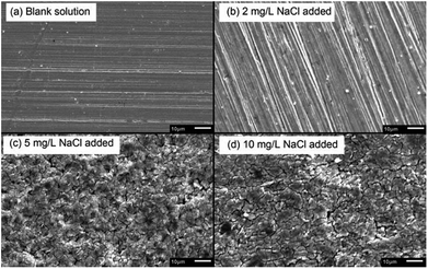 | ||
| Fig. 6 SEM micro-morphologies of products formed on X80 steel sample surface after galvanostatic polarization in different solutions. | ||
To differentiate the oxidation states of elements, the products were characterized by XPS after galvanostatic polarization. The high-resolution spectra and decomposition of Fe 2p, O 1s, S 2p, and Cl 2p are presented in Fig. 7 and 8.
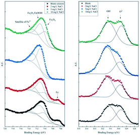 | ||
| Fig. 7 High-resolution XPS spectra of Fe 2p and O 1s of the products after galvanostatic polarization. | ||
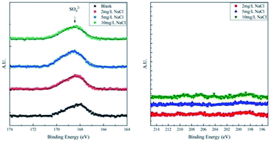 | ||
| Fig. 8 High-resolution XPS spectra of S 2p and Cl 2p of corrosion products on samples after galvanostatic polarization. | ||
In the XPS spectra of Fe 2p, we observe that three major peaks always exist. The peaks at ∼709 eV, ∼711 eV, and ∼713 eV are attributed to Fe3O4 (Fe II), Fe2O3/FeOOH (Fe III), and the satellite of Fe III, respectively.37,38 Moreover, a peak at ∼706.7 eV is observed for the samples in the blank solution and the solution with 2 mg L−1 NaCl. This peak was assigned to metallic Fe, suggesting that the thickness of the product layer was less than 10 nm.
The XPS spectra of O 1s consist of two large broad peaks centered at ∼529.9 eV and ∼531.3 eV, which are attributed to O2− and OH−.39 This result coincides with that of Fe 2p spectra of iron oxides and oxyhydroxides.
The XPS spectra of S 2p consist of only one weak peak at ∼168.5 eV. This peak40 is assigned to SO42−, which is the residual component of the solution. For the XPS spectra of Cl 2p, all the curves fluctuate weakly and no large peak is observed. This implies that all products are free of Cl−.
In a word, the main products of X80 steel after galvanostatic polarization are iron oxides and oxyhydroxides. However, Cl− ions alter the composition and the morphology of the products. In the blank solution and the solution with 2 mg L−1 NaCl, the products formed a thin and neat passivation film, preventing further corrosion of the sample. Therefore, this layer is indeed a mixture of Fe3O4, protective γ-Fe2O3, and amorphous FeOOH. Such results were in agreement with previously reported observations.41–44 In solutions with 5 and 10 mg L−1 NaCl, the steel samples were heavily corroded and the products were unprotected rusts. The products were Fe3O4, α-Fe2O3, and traditional FeOOH.
4. Discussion
The corrosion of carbon steel at a low current density has been extensively studied. The first step is widely recognized as the dissolution of steel and the formation of Fe2+ ions.45,46 The main electrochemical reaction is shown in eqn (2):| Fe → Fe2+ + 2e | (2) |
However, in high potential/current density conditions, the change in the polarization curves and the products implies a new electrochemical process, which has not been reported to date. Specifically, the mechanism and the influence of the Cl− ions are discussed below.
4.1 No Cl− ions
In Na2SO4 solution free of Cl− ions, the forward scan of the RPD test shows an apparent potential plateau, which is a potential jump after eliminating the IR drop. After the plateau, the rust drops and the products become strongly protective, implying the special passivation of steel. Correspondingly, the current density decreases from 0.117 A cm−2 to 0.077 A cm−2. It is deduced that the potential plateau is the transition from corrosion to passivation. The high potential is the requirement of passivation; however, it can be only achieved by a high current density.During passivation, a passivate film is formed (eqn (3)–(5)).39,47 It is believed that the passivate film of carbon steel has a layered structure.48,49 The outer layer mainly consists of the protective components of Fe3+ (γ-Fe2O3 and FeOOH50,51). The inner layer mainly consists of Fe3O4, which is the precursor of γ-Fe2O3.41–43,52 The passive film increases the potential of the sample surface; thus, most of the current density is consumed by the oxygen evolution reaction (OER) based on eqn (6).53
| 3Fe2+ + 4H2O → Fe3O4 + 8H+ + 2e | (3) |
| 2Fe3O4 + H2O → 3γ-Fe2O3 + 2H+ + 2e | (4) |
| Fe2+ + 2H2O → FeOOH + 3H+ + e | (5) |
| 2H2O → O2 + 4H+ + 4e | (6) |
In the backward scan, OER diminishes as the potential decreases and finally stops at the potential drop. The potential drop is very similar to the traditional passive stage, where only passive film generation reactions occur. Therefore, the minimum of the current density is a sign of the complete breakdown of the passivate film, and the corresponding potential is the lowest requirement of maintenance for passivation. Then, the passivate film is dissolved and the steel becomes corroded again after the second potential plateau (eqn (7)–(9)).
| γ-Fe2O3 + 6H+ → 2Fe3+ + 3H2O | (7) |
| FeOOH + 3H+ → Fe3+ + 2H2O | (8) |
| Fe3O4 + 8H+ → 2Fe3+ + Fe2+ + 4H2O | (9) |
4.2 Low content of Cl− ions
When the addition of NaCl is lower than 5 mg L−1, the shapes of the polarization curves do not change, indicating a similar process for film formation and OER. The current density at the start and the end of the potential plateau increases with the content of Cl− ions, as shown in Fig. 9. The steel requires more current density to transform from corrosion to passivation, indicating that the requirement of passivation increases. One possible reason is that a passivate film might be generated, but it can be thin and weak at the initial stage. Thus, it can be degraded by a small amount of Cl− ions.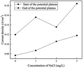 | ||
| Fig. 9 Influence of Cl− ions on the current density at the start and the end of the potential plateau in the forward scan. | ||
Furthermore, the proportion of the protective Fe3+ species decreased from 71.4% to 66.7%, which indicated that Cl− ions mainly attack the outer layer of the film. Then, the film thinned and weakened, which was in agreement with previously reported results.54 The attack of Cl− ions can be explained by the adsorption mechanism55,56 (eqn (10)–(12)). Cl− ions adsorbed at the film/solution interface could combine with the Fe3+ ions in the oxide and hydroxide to form a soluble complex. It is reasonable that such a complex with less positive charge requires less activation energy to be transferred from the oxide/hydroxide matrix to the electrolyte compared to that observed for highly charged Fe3+ ions. Then, the complex dissolved and released Cl− ions, which migrated towards the passivate film and reacted with other Fe3+ ions. The Cl− ions showed a catalytic effect. In this process, the high potential also plays an important role. Because the strong electric field at the film/solution interface could accelerate the migration of Cl− ions and enhance the adsorption, the small amount of Cl− ions could observably influence passivation.
| Fe3+(ox) + Cl−(ad) → FeCl2+(ad) | (10) |
| FeCl2+(ad) → FeCl2+(aq) | (11) |
| FeCl2+(aq) → Fe3+(aq) + Cl−(aq) | (12) |
| Cl−(aq) → Cl−(ad) | (13) |
In the backward scan, the minimum value of the current density and the corresponding potential increased with the content of Cl− ions, as shown in Fig. 10. This indicated that with the addition of Cl− ions, it is more difficult to maintain steel in the passivation state. The breakdown of the passivate film is advanced and the potential requirements of the transition from passivation to corrosion can be enhanced by Cl− ions.
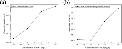 | ||
| Fig. 10 Influence of Cl− ions on (a) the minimum of the current density and (b) the corresponding potential in the backward scan. | ||
4.3 High content of Cl− ions
When the concentration of NaCl was higher than 5 mg L−1, steel was corroded in both forward and backward scans, and the passivation was completely prevented by Cl− ions. The main products were Fe3O4, α-Fe2O3 and FeOOH based on eqn (2) and (14)–(16). The total anodic process is similar to the forced electrolysis of steel. No pitting was found in the SEM images. The absence of hysteresis loops in the RPD curves was one piece of evidence.| 6Fe2+ + O2 + 6H2O → 2Fe3O4 + 12H+ | (14) |
| 4Fe2+ + O2 + 6H2O → 4FeOOH + 8H+ | (15) |
| 4Fe2+ + O2 + 4H2O → 2α-Fe2O3 + 8H+ | (16) |
Based on the results and analysis mentioned above, the model of passivation of X80 steel in Na2SO4 solution and the influence of Cl− ions are shown in Fig. 11. In Na2SO4 solution, X80 steel gets passivated at a high current density. When the concentration of Cl− ions is low (<5 mg L−1 NaCl), the steel can also be passivated; however, it needs higher requirements of potential and current density to form and maintain the passivation. When the concentration of Cl− ions was high (>5 mg L−1 NaCl), steel always corroded and no passivation could be achieved.
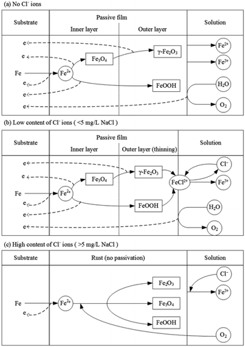 | ||
| Fig. 11 Reaction model of passivation of X80 steel in Na2SO4 solution and the influence of Cl− ions. | ||
Although many studies have reported the effect of Cl− ions on the passivation film of steel, most of them have focused on low potential and current density conditions. In high potential and current density conditions, the passivation of carbon steel and the effect of Cl− ions on such passivation are seldom studied. Our work may provide useful information for corrosion evaluation and protection in high voltage and current density interference cases.
5. Conclusions
(1) In Na2SO4 solution, X80 steel can get passivated in high potential/current density conditions. In the forward scan of the RPD test, the potential plateau is the transition from corrosion to passivation. The passivate film is composed of Fe3O4, γ-Fe2O3, and FeOOH. In the backward scan, the passivate film breaks at the minimum of the current density, and the steel gets corroded after the second plateau.(2) A small amount of Cl− ions can have a considerable influence on passivation.
When the concentration of Cl− ions was low (<5 mg L−1 NaCl), the steel was still passivated in high potential/current density conditions. However, the requirements of obtaining passivation (in the forward scan) and maintaining the passivation (in the backward scan) are enhanced by Cl− ions.
When the concentration of Cl− ions was high (>5 mg L−1 NaCl), the steel corroded and did not get passivated at all. The corrosion products were mainly composed of Fe3O4, α-Fe2O3, and traditional FeOOH.
Conflicts of interest
There are no conflicts to declare.Acknowledgements
The authors are grateful for National Key R&D Program of China (grant number 2016YFC0802101).Notes and references
- Y. Gong, C. Xue, Z. Yuan, Y. Li and F. P. Dawalibi, Journal of Power and Energy Engineering, 2015, 03, 332–341 CrossRef
.
- R. Qin, Y. Du, Z. Jiang, X. Wang, A. Fu and Y. Lu, Metals, 2018, 8, 809–823 CrossRef
.
- R. Qin, Y. Du, G. Peng, M. Lu and Z. Jiang, Proceedings of the Corrosion 2017, vol. 1, pp. 488–498 Search PubMed
.
- Y. Song, G. Jiang, Y. Chen, P. Zhao and Y. Tian, Sci. Rep., 2017, 1–13 Search PubMed
.
- I. S. Cole and D. Marney, Corros. Sci., 2012, 56, 5–16 CrossRef CAS
.
- Z. Jiang, Y. Du, M. Lu, Y. Zhang, D. Tang and L. Dong, Corros. Sci., 2014, 81, 1–10 CrossRef CAS
.
- P. Smith, S. Roy, D. Swailes, S. Maxwell, D. Page and J. Lawson, Chem. Eng. Sci., 2011, 66, 5775–5790 CrossRef CAS
.
- S. Goidanich, L. Lazzari and M. Ormellese, Corros. Sci., 2010, 52, 491–497 CrossRef CAS
.
- P. Morales Gil, B. Julien, M. Palomar-Pardavé, M. G. Montes de Oca-Yemha, M. T. Ramírez-Silva and M. Romero-Romo, Int. J. Electrochem. Sci., 2018, 13, 3297–3308 CrossRef
.
- X. Zhang, K. XIAO, C. Dong, J. Wu, X. Li and Y. Huang, Eng. Failure Anal., 2011, 18, 1981–1989 CrossRef CAS
.
- S. Arzola, M. E. Palomar-Pardavé and J. Genesca, J. Appl. Electrochem., 2003, 33, 1233–1237 CrossRef
.
- I. M. Gadala and A. Alfantazi, Corros. Sci., 2014, 82, 45–57 CrossRef CAS
.
- C. Ren, X. Wang, L. Liu, H. Yang and N. Xian, Mater. Corros., 2010, 61, 1–5 CrossRef
.
- Y. Hu, C. Dong, M. Sun, K. Xiao, P. Zhong and X. Li, Corros. Sci., 2011, 53, 4159–4165 CrossRef CAS
.
- Y. F. Cheng and J. L. Luo, Electrochim. Acta, 1999, 44, 2947–2957 CrossRef CAS
.
- F. F. Eliyan, E.-S. Mahdi and A. Alfantazi, Corros. Sci., 2012, 58, 181–191 CrossRef CAS
.
- H. Yu, K.-T. K. Chiang and L. Yang, Constr. Build. Mater., 2012, 26, 723–729 CrossRef
.
- K. Y. Ann and H.-W. Song, Corros. Sci., 2007, 49, 4113–4133 CrossRef CAS
.
- D. Rivas, F. Caleyo, A. Valor and J. M. Hallen, Corros. Sci., 2008, 50, 3193–3204 CrossRef CAS
.
- L. Li and A. A. Sagüés, Corrosion, 2002, 58, 305–316 CrossRef CAS
.
- M. Saremi and E. Mahallati, Cem. Concr. Res., 2002, 32, 1915–1921 CrossRef CAS
.
- E.-S. M. Sherif, A. A. Almajid, K. A. Khalil, H. Junaedi and F. H. Latief, Int. J. Electrochem. Sci., 2013, 8, 9360–9370 CAS
.
- D. Cicolin, M. Trueba and S. P. Trasatti, Electrochim. Acta, 2014, 124, 27–35 CrossRef CAS
.
- P. Ghods, O. B. Isgor, G. A. McRae and G. P. Gu, Corros. Sci., 2010, 52, 1649–1659 CrossRef CAS
.
- H. Luo, H. Su, C. Dong and X. Li, Appl. Surf. Sci., 2017, 400, 38–48 CrossRef CAS
.
- J. Wang, S. Qian, Y. Li, D. D. Macdonald, Y. Jiang and J. Li, J. Mater. Sci. Technol., 2018, 1–20 Search PubMed
.
- I. M. Gadala and A. Alfantazi, Appl. Surf. Sci., 2015, 357, 356–368 CrossRef CAS
.
- P. Ghods, O. B. Isgor, F. Bensebaa and D. Kingston, Corros. Sci., 2012, 58, 159–167 CrossRef CAS
.
- P. Ghods, O. B. Isgor, J. R. Brown, F. Bensebaa and D. Kingston, Appl. Surf. Sci., 2011, 257, 4669–4677 CrossRef CAS
.
- B. Zhang, J. Wang, B. Wu, X. W. Guo, Y. J. Wang, D. Chen, Y. C. Zhang, K. Du, E. E. Oguzie and X. L. Ma, Nat. Commun., 2018, 9(1), 2559–2567 CrossRef CAS PubMed
.
- D. D. Macdonald, Electrochim. Acta, 2011, 56, 1761–1772 CrossRef CAS
.
- D. G. Li, Y. R. Feng, Z. Q. Bai, J. W. Zhu and M. S. Zheng, Electrochim. Acta, 2007, 52, 7877–7884 CrossRef CAS
.
- Q. Y. Liu, L. J. Mao and S. W. Zhou, Corros. Sci., 2014, 84, 165–171 CrossRef CAS
.
- W. Oelßner, F. Berthold and U. Guth, Mater. Corros., 2006, 57, 455–466 CrossRef
.
- B. Elsener, Corros. Sci., 2005, 47, 3019–3033 CrossRef CAS
.
- D. de la Fuente, I. Díaz, J. Simancas, B. Chico and M. Morcillo, Corros. Sci., 2011, 53, 604–617 CrossRef CAS
.
- S. Guo, L. Xu, L. Zhang, W. Chang and M. Lu, Corros. Sci., 2016, 110, 123–133 CrossRef CAS
.
- W. Xu, K. Daub, X. Zhang, J. J. Noel, D. W. Shoesmith and J. C. Wren, Electrochim. Acta, 2009, 54, 5727–5738 CrossRef CAS
.
- Y. Li and Y. F. Cheng, Appl. Surf. Sci., 2017, 396, 144–153 CrossRef CAS
.
- Z. U. Rahman, K. M. Deen, L. Cano and W. Haider, Appl. Surf. Sci., 2017, 410, 432–444 CrossRef
.
- M.-I. Nagayama and M. Cohen, J. Electrochem. Soc., 1962, 109, 781–790 CrossRef CAS
.
- C. L. Foley, J. Kruger and C. J. Bechtoldt, J. Electrochem. Soc., 1967, 114, 994–1001 CrossRef CAS
.
- K. Kuroda, B. D. Cahan, G. Nazri, E. Yeager and T. E. Mitchell, J. Electrochem. Soc., 1982, 129, 2163–2169 CrossRef CAS
.
- W. E. O'Grady, Mössbauer Study of the Passive Oxide Film on Iron, J. Electrochem. Soc., 1980, 127, 555–563 CrossRef
.
- J. O. M. Bockris, D. Drazic and A. R. Despic, Electrochim. Acta, 1961, 4, 325–361 CrossRef CAS
.
- R. S. Gonçalves and L. D. Mello, Corros. Sci., 2001, 43, 457–470 CrossRef
.
- K. Daub, X. Zhang, L. Wang, Z. Qin, J. J. Noel and J. C. Wren, Electrochim. Acta, 2011, 56, 6661–6672 CrossRef CAS
.
- M. Büchler, P. Schmuki and H. Böhni, J. Electrochem. Soc., 1997, 144, 2307–2312 CrossRef
.
- J. Gui and T. M. Devine, Corros. Sci., 1991, 32, 1105–1124 CrossRef CAS
.
- A. M. P. Simões, M. G. S. Ferreira, B. Rondot and M. D. Da Cunha Belo, J. Electrochem. Soc., 1990, 137, 82–87 CrossRef
.
- J. C. Rubim and J. Dünnwald, J. Electroanal. Chem., 1989, 258, 327–344 CrossRef CAS
.
- D. G. Li, Y. R. Feng, Z. Q. Bai, J. W. Zhu and M. S. Zheng, Appl. Surf. Sci., 2008, 254, 2837–2843 CrossRef CAS
.
- G. N. Martelli, R. Ornelas and G. Faita, Electrochim. Acta, 1994, 39, 1551–1558 CrossRef CAS
.
- P. Ghods, O. B. Isgor, G. J. C. Carpenter, J. Li, G. A. McRae and G. P. Gu, Cem. Concr. Res., 2013, 47, 55–68 CrossRef CAS
.
- K. J. Vetter and F. Gorn, Electrochim. Acta, 1973, 18, 321–326 CrossRef CAS
.
- R. P. Frankenthal, Electrochim. Acta, 1971, 16, 1845–1857 CrossRef CAS
.
| This journal is © The Royal Society of Chemistry 2019 |

