 Open Access Article
Hybrid cellulose nanocrystal/alginate/gelatin scaffold with improved mechanical properties and guided wound healing
Yue Shan,
Chaoyue Li,
Yongzhi Wu,
Qiwen Li and
Jinfeng Liao *
*
State Key Laboratory of Oral Diseases, National Clinical Research Centre for Oral Diseases, West China Hospital of Stomatology, Sichuan University, Chengdu, 610041, China. E-mail: liaojinfeng.762@163.com
First published on 25th July 2019
Abstract
Nature derived biopolymers such as polysaccharides and collagen have attracted considerable attention in biomedical applications. Despite excellent biocompatibility and bioactivity, their poor mechanical properties could not meet the requirement for skin regeneration. In this study, cellulose nanocrystal (CNC) was incorporated into the calcium cross-linked sodium alginate/gelatin (SA/Ge) scaffold to reinforce its physicochemical properties. A novel sodium alginate/gelatin/cellulose nanocrystal (SA/Ge/CNC) scaffold was successfully prepared through electrostatic interaction of sodium alginate and gelatin, ionic cross-linking of calcium ions with sodium alginate, and incorporation of CNC. Afterwards, the SA/Ge and SA/Ge/CNC scaffolds were fully characterized and compared with scanning electron microscopy images, swelling behaviors, tensile strengths and contact angles. The involvement of CNC produces a hybrid SA/Ge/CNC scaffold with desired porous network, moderate swelling behavior, and superior mechanical strength (from 18 MPa to 45 MPa). Furthermore, in vitro cytotoxicity and cell growth assay using mouse embryonic fibroblast cells validated that SA/Ge/CNC scaffold was non-toxic and can prompt cell adhesion and proliferation. The in vivo skin regeneration experiments using the SA/Ge/CNC scaffold group showed an improved skin wound healing process with accelerated re-epithelialization, increased collagen deposition and faster extracellular matrix remodeling. Overall, the results suggested that the SA/Ge/CNC hybrid scaffold with enhanced mechanical performance and wound healing efficacy was a promising biomaterial for skin defect regeneration.
1. Introduction
Skin is the largest and one of the most important organs of humans, acting as a protective blockage to the invasion of harmful microorganisms and damage from certain environmental conditions.1,2 Dermal tissue defects following burns, surgical excision, skin trauma and chronic ulcers remain a challenging clinical problem and cause a substantial cost burden on the public.3,4 The traditional treatments for skin repair include implantation of autologous, allogeneic and exogenous skin grafts, which are usually constricted by the lack of donor sources, costly medical expenses and undesirable immunological response.5,6 Therefore, it is urgently desirable to develop an ideal substitute which is structurally, functionally, and mechanically similar to healthy skin.7 The recovery of injured skin tissue is a highly ordered biological process, which involves hemostasis, inflammation reaction, formation of granulation tissue, re-epithelialization, and matrix remodeling.8,9 With better understanding of the wound repair and management process, numerous biomaterials have been created to mimic the natural environment for skin regeneration, and accelerate cell proliferation and induce extracellular matrix (ECM) reproduction.10,11To date, a number of naturally derived polymers, including polysaccharides and proteins have been widely utilized in the field of tissue engineering scaffolds, due to their excellent hydrophilicity, biodegradability and biocompatibility.12–14 In particular, sodium alginate, a seaweed-derived polysaccharides, is preferred for its gelling property, excellent biocompatibility, and source-abundance.15–17 Besides, alginate is composed of consecutive and alternately arranged α-L-guluronic and β-D-mannuronic blocks and is able to cross-link with divalent metal ions (e.g. Ca2+, Zn2+).18,19 Collagen is an important component of skin and provides resistance to connective tissues. Gelatin is a hydrolyzed product from collagen with desired features of prompting hemostasis and guiding cell adherence, proliferation and differentiation.15,20 Combining two or more different polymers by cross-linkers has been reported to be an effective method to create a new scaffold, which can get rid of their disadvantages and integrate their advantages.21,22 For example, the composite materials blending alginate with gelatin together have gained much attention because of superior physicochemical and biological properties.23,24 That hybrid alginate/gelatin materials get over the respective drawbacks of constituents, such as the rapid degradation rate, high swelling degree of gelatin, and weak mechanical properties of alginate.25 Nevertheless, the composite materials still existed some limitations like inadequate mechanical strength and loose network structure.26
To overcome these deficiencies, we integrated cellulose nanocrystals (CNC) into the composite scaffolds as a functional additive to improve their physical, chemical and biological performances. CNC is a kind of unique nanomaterial, which derived from natural cellulose fibers.27 It has excellent properties of high aspect ratio, low toxicity, excellent mechanical performance and good biocompatibility. One major application of CNC is acting as reinforcing agent in composites. It is well known that the high mechanical strength of CNC ascribed to its highly crystalline structure and the existence of intra- and inter-molecular hydrogen bonds. The incorporation of CNC can form effective interfacial interaction between the reinforcement material and matrix. Furthermore, the large surface area and abundant surface hydroxyl groups of CNC provide the possibility of chemical modifications and drug delivery. Due to its outstanding characteristics, CNC has been considered as an ideal reinforcing component for polymer matrix integration.21,28,29 The combination of CNC with sodium alginate and gelatin is expected to synthesize a nanocomposite with improved mechanical and biological properties.
To date, most skin substitutes and tissue engineered scaffolds are still in the research and development stages. The current commercialized products such as Dermagraft, Apligraf, MatriDerm, PriMatrix and AlloDerm should be viewed as “smart dressings”, rather than true skin equivalents. They are cellularized, decellularized or bioengineered matrices that maintain and support a healing environment through facilitating cell adhesion and proliferation, as well as skin appendages regeneration.30 In this study, a novel hybrid scaffold comprised of sodium alginate, gelatin and CNC was prepared by using the solvent casting method. Compared with the commercial products, the SA/Ge/CNC scaffold reconstructs and remodels wounds in a similar way. Moreover, the SA/Ge/CNC scaffold is inexpensive, renewable, biocompatible, and easy to prepare in a large scale.
As shown in Scheme 1A, the synthesis of SA/Ge/CNC scaffold involved electrostatic interaction of gelatin and alginate, incorporation of cellulose nanocrystals and crosslinking of alginate with calcium ions. The appropriate sodium alginate/gelatin ratio and CNC concentration were systemically investigated and chosen. All the scaffolds were characterized in terms of their structures, swelling behaviors, mechanical properties and contact angles. Additionally, mouse embryonic fibroblast cells (NIH 3T3) were used to assess the in vitro cyto-compatibility of scaffolds. Finally, in vivo wound repair experiments on full-thickness excision wound models of SD rats were further implemented to evaluate their biological application potential through both macroscopic and microscopic observation (Scheme 1B). The results demonstrated that SA/Ge/CNC scaffold can be considered as a potential substitute for skin tissue engineering.
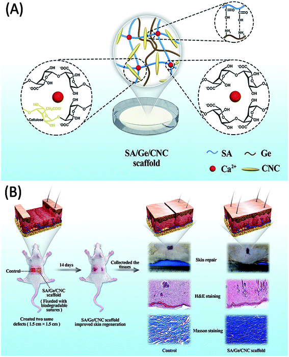 | ||
| Scheme 1 (A) The illustration of the SA/Ge/CNC scaffold. (B) The skin regeneration improved by the SA/Ge/CNC scaffold in SD rats. | ||
2. Materials and methods
2.1 Materials
Sodium alginate (from brown algae, molecular weight of 20–40 kDa) and gelatin (Type B, from porcine skin) were purchased from Sigma-Aldrich (USA). Cellulose nanocrystals (CNC, extracted from cotton pulp, prepared by sulfuric acid hydrolysis, length between 150–200 nm, diameter 4–7 nm; solid content about 1.2 wt% in suspension) was obtained from Haojia Chemicals, Tianjin, China. Anhydrous CaCl2, chloral hydrate (10%) and phosphate buffer saline (PBS, pH = 7.4) were acquired from Kelong Chemicals, Chengdu, China. 3-(4,5-Dimethylthiazol-2-yl)-2,5-diphenyltetrazolium bromide (MTT) and dimethyl sulfoxide (DMSO) were purchased from Shanghai Aladdin Bio-Chem Technology Co., Ltd. Dulbecco's Modified Eagle's Medium (DMEM), fetal bovine serum (FBS), penicillin and all other culture media and reagents were purchased from Gibco™ (United States). All the reagents were of laboratory reagent grade.For the skin regeneration study, 12 male rats weighing 200–220 g were obtained from Chengdu Dashuo Experimental Animal Co., Ltd. All the surgical procedures on rats were approved by the animal care and use committee of State Key Laboratory of Oral Diseases, Sichuan University. During the experiment, all the animals were kept in individual cages and were fed with a commercial rat food and water ad libitum.
2.2. Methods
| Sample | 3 wt% Alginate (ml) | 3 wt% Gelatin (ml) | 1 wt% CNC (ml) | H2O (ml) |
|---|---|---|---|---|
SA/Ge (1![[thin space (1/6-em)]](https://www.rsc.org/images/entities/char_2009.gif) : :![[thin space (1/6-em)]](https://www.rsc.org/images/entities/char_2009.gif) 2) 2) |
30 | 60 | 0 | 0 |
SA/Ge (1![[thin space (1/6-em)]](https://www.rsc.org/images/entities/char_2009.gif) : :![[thin space (1/6-em)]](https://www.rsc.org/images/entities/char_2009.gif) 1) 1) |
45 | 45 | 0 | 0 |
SA/Ge (2![[thin space (1/6-em)]](https://www.rsc.org/images/entities/char_2009.gif) : :![[thin space (1/6-em)]](https://www.rsc.org/images/entities/char_2009.gif) 1) 1) |
60 | 30 | 0 | 0 |
SA/Ge (4![[thin space (1/6-em)]](https://www.rsc.org/images/entities/char_2009.gif) : :![[thin space (1/6-em)]](https://www.rsc.org/images/entities/char_2009.gif) 1) 1) |
72 | 18 | 0 | 0 |
| SA/Ge/CNC (0) | 40 | 20 | 0 | 5 |
| SA/Ge/CNC (0.1%) | 40 | 20 | 0.5 | 4.5 |
| SA/Ge/CNC (0.5%) | 40 | 20 | 2.5 | 2.5 |
| SA/Ge/CNC (1%) | 40 | 20 | 5 | 0 |
2.3 Characterization of scaffolds
| Swelling degree (%) = (W2 − W1)/W1 × 100% |
| σ = Fb/So |
2.4 In vitro cell viability and cell morphology assay
The in vitro cell viability of SA/Ge/CNC scaffold was measured by MTT assay. In this study, NIH 3T3 cells were selected. The cells were seeded in 96-well plates and incubated under a humidified atmosphere in the presence of 5% CO2 at 37 °C. After being sterilized with ethylene oxide for 8 h, the scaffolds (100 mg) were then immersed in DMEM solution (1 ml) for 24 h to extract the leachate. Subsequently, the original leachate (100 mg ml−1) were diluted to various concentrations (0.78, 1.56, 3.13, 6.25, 12.5, 25, 50 and 75 mg ml−1, n = 6). Then, 100 μl leachate at each concentration was added into culture wells separately. The culture wells without leachate were set as control and wells with leachate were used as the experimental groups. After incubation for 1 d, 20 μl of MTT solution (5 mg ml−1) was added into each well and further cultured at 37 °C for 4 h. Afterwards, the medium was replaced by 150 μl DMSO solution for each well to dissolve the formed formazan crystals. The ultra-violet (UV) absorbance at 570 nm was quantified using an ELISA reader (BioTek Instruments, Inc., Winooski, Vermont, USA).For the cell morphology and adherence evaluation, NIH 3T3 cells were seeded onto SA/Ge/CNC scaffolds in humidified condition at 37 °C and 5% CO2. After incubation for 3 days, the scaffolds were fixed with 2.5% glutaraldehyde solution for 2 h and then rinsed with PBS (pH = 7.4) for at least three times. Afterwards, the scaffolds were dehydrated twice in a series of graded ethanol. Finally, the samples were visualized by SEM and the images were photographed.
2.5 Skin regeneration in SD rats
Twelve healthy 8 week-old male SD rats (weighing 200–220 g) were randomly divided into two groups: (1) SA/Ge group, and (2) SA/Ge/CNC group; each group had 6 animals. All the rats were anaesthetized by an injection of 10% chloral hydrate (2.5 ml kg−1) and removed the dorsal hair with a shaving machine. After disinfecting with iodophor, two square full-thickness excision defects (1.5 cm × 1.5 cm) were created symmetrically on the bilateral sides of each SD rat's back using surgical scissors (Scheme 1B). The SA/Ge scaffolds and SA/Ge/CNC scaffolds were covered on the right defects (anatomical position). At four corners of wounds, biodegradable sutures were applied for fixation. Wounds on the left side of both groups were set as a control, which were not treated with scaffolds. Finally, all the wounds on both sides were covered with dressings (3M Health Care, Germany) for protection. At 7 and 14 days after treatment, the macroscopic morphology of defects were observed and photographed at a stable distance. Then, rats were sacrificed to collect wound skin along with surrounding healthy tissues for further study (3 rats from each group on days 7 and 14 post-wounding). The harvested tissue samples were fixed in 10% formaldehyde overnight. After a series of dehydration procedures with graded ethanol, the tissues were embedded in paraffin and sectioned into 5 μm thick slices for hematoxylin–eosin (H&E) and Masson's trichrome staining. The sections were observed by a microscope (Nikon ECLPSE, Japan) and the images were captured.2.6 Statistical analysis
The statistical analysis was performed by SPSS 25.0 software (SPSS Inc., Chicago, IL, USA). The mean values and standard deviations were calculated for the pore size, swelling percentage, mechanical strength, contact angle, in vitro cell viability and in vivo skin defect regeneration research. P values < 0.05 indicates a statistically significant difference.3. Results and discussion
3.1 Selection of the optimum ratio of SA/Ge in scaffold
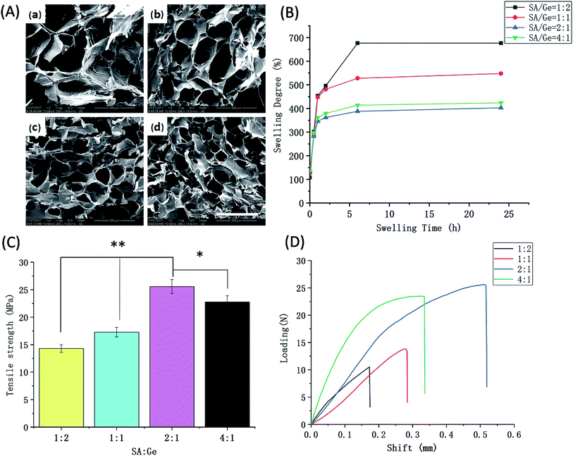
Before preparation of SA/Ge/CNC hybrid scaffold, the optimum ratio of SA and Ge in SA/Ge scaffold was investigated firstly. The scaffolds were measured various physical properties such as morphology, swelling behavior, and mechanical strength, etc. The pore size and distribution among scaffolds are highly related to cell adherence, proliferation, and nutrient exchange in matrix.20 Scaffold with porous structure renders fast efficiency of biomolecules transportation with environment and is an ideal material for the skin tissue engineering.31 Fig. 1A shows the SEM photographs of SA/Ge scaffolds with different ratios at ×200 magnification. The cross-section morphology of all scaffolds presented a porous and interconnected structure. The average pore dimension of scaffolds was displayed in Table 2. It was observed that as the ratios of SA/Ge increased, pores in scaffolds became more homogeneous and the pore size appeared smaller. On the contrary, the increased proportion of Ge led to a more disordered and non-uniform composite network with larger pores. Additionally, the pore size of SA![[thin space (1/6-em)]](https://www.rsc.org/images/entities/char_2009.gif) :
:![[thin space (1/6-em)]](https://www.rsc.org/images/entities/char_2009.gif) Ge = 2
Ge = 2![[thin space (1/6-em)]](https://www.rsc.org/images/entities/char_2009.gif) :
:![[thin space (1/6-em)]](https://www.rsc.org/images/entities/char_2009.gif) 1 group and SA
1 group and SA![[thin space (1/6-em)]](https://www.rsc.org/images/entities/char_2009.gif) :
:![[thin space (1/6-em)]](https://www.rsc.org/images/entities/char_2009.gif) Ge = 4
Ge = 4![[thin space (1/6-em)]](https://www.rsc.org/images/entities/char_2009.gif) :
:![[thin space (1/6-em)]](https://www.rsc.org/images/entities/char_2009.gif) 1 group showed no much significant difference in SEM images.
1 group showed no much significant difference in SEM images.
| Sample | SA/Ge | SA/Ge/CNC | ||||||
|---|---|---|---|---|---|---|---|---|
1![[thin space (1/6-em)]](https://www.rsc.org/images/entities/char_2009.gif) : :![[thin space (1/6-em)]](https://www.rsc.org/images/entities/char_2009.gif) 2 2 |
1![[thin space (1/6-em)]](https://www.rsc.org/images/entities/char_2009.gif) : :![[thin space (1/6-em)]](https://www.rsc.org/images/entities/char_2009.gif) 1 1 |
2![[thin space (1/6-em)]](https://www.rsc.org/images/entities/char_2009.gif) : :![[thin space (1/6-em)]](https://www.rsc.org/images/entities/char_2009.gif) 1 1 |
4![[thin space (1/6-em)]](https://www.rsc.org/images/entities/char_2009.gif) : :![[thin space (1/6-em)]](https://www.rsc.org/images/entities/char_2009.gif) 1 1 |
Without CNC | CNC (0.1%) | CNC (0.5%) | CNC (1%) | |
| Average pore size (μm) | 302 ± 43 | 276 ± 31 | 165 ± 30 | 177 ± 24 | 210 ± 40 | 183 ± 27![[thin space (1/6-em)]](https://www.rsc.org/images/entities/char_2009.gif) |
157 ± 31 | 120 ± 16 |
The swelling behavior of scaffolds is a crucial feature in terms of its potential for skin regeneration applications. An appropriate swelling degree can maintain the moist environment of wound and protect it from excessive dehydration. At the same time, the swelling ability influences the diffusion of nutrition and absorption of exudates.9 Thus, the swelling behavior of different SA/Ge scaffolds were tested. As shown in Fig. 1B, the four groups all indicated continuous enhancement of swelling degree and reached equilibrium after being immersed in PBS for approximately 6 h. Compared with the other three groups, the group of SA![[thin space (1/6-em)]](https://www.rsc.org/images/entities/char_2009.gif) :
:![[thin space (1/6-em)]](https://www.rsc.org/images/entities/char_2009.gif) Ge = 1
Ge = 1![[thin space (1/6-em)]](https://www.rsc.org/images/entities/char_2009.gif) :
:![[thin space (1/6-em)]](https://www.rsc.org/images/entities/char_2009.gif) 2 displayed the maximum swelling degree of 677%. Subsequently, a decline of swelling degree was observed as the ratio of SA/Ge increased from 1
2 displayed the maximum swelling degree of 677%. Subsequently, a decline of swelling degree was observed as the ratio of SA/Ge increased from 1![[thin space (1/6-em)]](https://www.rsc.org/images/entities/char_2009.gif) :
:![[thin space (1/6-em)]](https://www.rsc.org/images/entities/char_2009.gif) 2 to 1
2 to 1![[thin space (1/6-em)]](https://www.rsc.org/images/entities/char_2009.gif) :
:![[thin space (1/6-em)]](https://www.rsc.org/images/entities/char_2009.gif) 1 and 2
1 and 2![[thin space (1/6-em)]](https://www.rsc.org/images/entities/char_2009.gif) :
:![[thin space (1/6-em)]](https://www.rsc.org/images/entities/char_2009.gif) 1, whose swelling degree were 677%, 548%, 403%, respectively. However, the swelling degree of SA
1, whose swelling degree were 677%, 548%, 403%, respectively. However, the swelling degree of SA![[thin space (1/6-em)]](https://www.rsc.org/images/entities/char_2009.gif) :
:![[thin space (1/6-em)]](https://www.rsc.org/images/entities/char_2009.gif) Ge = 2
Ge = 2![[thin space (1/6-em)]](https://www.rsc.org/images/entities/char_2009.gif) :
:![[thin space (1/6-em)]](https://www.rsc.org/images/entities/char_2009.gif) 1 group (403%) was slightly lower than that of SA
1 group (403%) was slightly lower than that of SA![[thin space (1/6-em)]](https://www.rsc.org/images/entities/char_2009.gif) :
:![[thin space (1/6-em)]](https://www.rsc.org/images/entities/char_2009.gif) Ge = 4
Ge = 4![[thin space (1/6-em)]](https://www.rsc.org/images/entities/char_2009.gif) :
:![[thin space (1/6-em)]](https://www.rsc.org/images/entities/char_2009.gif) 1 group (425%) (p < 0.05). This phenomenon was in accordance with the results of morphology analysis. Yuan et al. reported that swelling behavior is related to the composition and cross-linking degree of the scaffold.17 The high swelling degree of SA/Ge scaffolds might be due to plenty of hydrophilic groups on SA and Ge molecules. Besides, it is reported that the higher density the scaffold is, the lower swelling degree it possesses. The 2
1 group (425%) (p < 0.05). This phenomenon was in accordance with the results of morphology analysis. Yuan et al. reported that swelling behavior is related to the composition and cross-linking degree of the scaffold.17 The high swelling degree of SA/Ge scaffolds might be due to plenty of hydrophilic groups on SA and Ge molecules. Besides, it is reported that the higher density the scaffold is, the lower swelling degree it possesses. The 2![[thin space (1/6-em)]](https://www.rsc.org/images/entities/char_2009.gif) :
:![[thin space (1/6-em)]](https://www.rsc.org/images/entities/char_2009.gif) 1 group with higher degree of cross-linking possessed denser network, smaller pore size and less space to trap the liquid, which contributed to its lower swelling degree.
1 group with higher degree of cross-linking possessed denser network, smaller pore size and less space to trap the liquid, which contributed to its lower swelling degree.
The mechanical properties of different groups were presented in Fig. 1C and D, which showed the ultimate tensile strength and shift–loading curves, respectively. The tensile strength of four groups was in the range of 14.3–25.6 MPa. Among the four groups, SA/Ge = 1![[thin space (1/6-em)]](https://www.rsc.org/images/entities/char_2009.gif) :
:![[thin space (1/6-em)]](https://www.rsc.org/images/entities/char_2009.gif) 2 group with higher content of gelatin had the lowest mechanical strength of 14.3 MPa, while the tensile strength of SA/Ge = 1
2 group with higher content of gelatin had the lowest mechanical strength of 14.3 MPa, while the tensile strength of SA/Ge = 1![[thin space (1/6-em)]](https://www.rsc.org/images/entities/char_2009.gif) :
:![[thin space (1/6-em)]](https://www.rsc.org/images/entities/char_2009.gif) 1 group increased to 17.3 MPa after decreasing the ratio of gelatin. Meanwhile, SA/Ge = 2
1 group increased to 17.3 MPa after decreasing the ratio of gelatin. Meanwhile, SA/Ge = 2![[thin space (1/6-em)]](https://www.rsc.org/images/entities/char_2009.gif) :
:![[thin space (1/6-em)]](https://www.rsc.org/images/entities/char_2009.gif) 1 group displayed the best mechanical behavior of 25.6 MPa, which had slight superiority over the SA/Ge = 4
1 group displayed the best mechanical behavior of 25.6 MPa, which had slight superiority over the SA/Ge = 4![[thin space (1/6-em)]](https://www.rsc.org/images/entities/char_2009.gif) :
:![[thin space (1/6-em)]](https://www.rsc.org/images/entities/char_2009.gif) 1 group (22.8 MPa). The results of mechanical properties were in accordance with the pore dimension. SA/Ge scaffolds with smaller pore sizes also exhibited better mechanical performance because of higher cross-linking degree and more entangled network structure.
1 group (22.8 MPa). The results of mechanical properties were in accordance with the pore dimension. SA/Ge scaffolds with smaller pore sizes also exhibited better mechanical performance because of higher cross-linking degree and more entangled network structure.
Overall, the results from the morphology, pore size, swelling behavior, and tensile strength tests were comprehensively considered. The SEM results indicated that the pore size of SA![[thin space (1/6-em)]](https://www.rsc.org/images/entities/char_2009.gif) :
:![[thin space (1/6-em)]](https://www.rsc.org/images/entities/char_2009.gif) Ge = 2
Ge = 2![[thin space (1/6-em)]](https://www.rsc.org/images/entities/char_2009.gif) :
:![[thin space (1/6-em)]](https://www.rsc.org/images/entities/char_2009.gif) 1 group and SA
1 group and SA![[thin space (1/6-em)]](https://www.rsc.org/images/entities/char_2009.gif) :
:![[thin space (1/6-em)]](https://www.rsc.org/images/entities/char_2009.gif) Ge = 4
Ge = 4![[thin space (1/6-em)]](https://www.rsc.org/images/entities/char_2009.gif) :
:![[thin space (1/6-em)]](https://www.rsc.org/images/entities/char_2009.gif) 1 group were similar and both presented a homogeneous and dense network with suitable pore size. Moreover, SA/Ge scaffold at ratio of 2
1 group were similar and both presented a homogeneous and dense network with suitable pore size. Moreover, SA/Ge scaffold at ratio of 2![[thin space (1/6-em)]](https://www.rsc.org/images/entities/char_2009.gif) :
:![[thin space (1/6-em)]](https://www.rsc.org/images/entities/char_2009.gif) 1 displayed more excellent mechanical performance than the other three groups. Besides, SA
1 displayed more excellent mechanical performance than the other three groups. Besides, SA![[thin space (1/6-em)]](https://www.rsc.org/images/entities/char_2009.gif) :
:![[thin space (1/6-em)]](https://www.rsc.org/images/entities/char_2009.gif) Ge = 2
Ge = 2![[thin space (1/6-em)]](https://www.rsc.org/images/entities/char_2009.gif) :
:![[thin space (1/6-em)]](https://www.rsc.org/images/entities/char_2009.gif) 1 group also possessed a moderate swelling degree which could provide a relative humid environment for wounds without excessive dehydration.32–34 Thus, from the above results, the ratio of SA
1 group also possessed a moderate swelling degree which could provide a relative humid environment for wounds without excessive dehydration.32–34 Thus, from the above results, the ratio of SA![[thin space (1/6-em)]](https://www.rsc.org/images/entities/char_2009.gif) :
:![[thin space (1/6-em)]](https://www.rsc.org/images/entities/char_2009.gif) Ge = 2
Ge = 2![[thin space (1/6-em)]](https://www.rsc.org/images/entities/char_2009.gif) :
:![[thin space (1/6-em)]](https://www.rsc.org/images/entities/char_2009.gif) 1 was selected for further study with CNC to deeply improve its properties.
1 was selected for further study with CNC to deeply improve its properties.
3.2 Morphology and chemical evaluation of CNC and SA/Ge/CNC scaffold
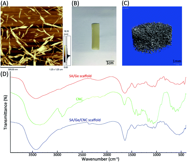
In order to observe the morphology of CNC in detail, the original suspension (1.2 wt%) was diluted to the concentration of 0.01 wt% and observed by AFM. The results exhibited that CNC possessed a long spindle-like shape with the length between 150–200 nm (Fig. 2A). The macroscopic photograph of SA/Ge/CNC scaffold (SA![[thin space (1/6-em)]](https://www.rsc.org/images/entities/char_2009.gif) :
:![[thin space (1/6-em)]](https://www.rsc.org/images/entities/char_2009.gif) Ge = 2
Ge = 2![[thin space (1/6-em)]](https://www.rsc.org/images/entities/char_2009.gif) :
:![[thin space (1/6-em)]](https://www.rsc.org/images/entities/char_2009.gif) 1, 0.5 wt% CNC) was documented by digital camera and displayed in Fig. 2B. The SA/Ge/CNC scaffold possesses an opaque appearance with light yellow color. Furthermore, micro-CT analysis was programmed to reconstruct the inner micro-morphology and investigate the porosity of SA/Ge/CNC scaffold. Fig. 2C showed the micro-CT scan result of SA/Ge/CNC sample (SA
1, 0.5 wt% CNC) was documented by digital camera and displayed in Fig. 2B. The SA/Ge/CNC scaffold possesses an opaque appearance with light yellow color. Furthermore, micro-CT analysis was programmed to reconstruct the inner micro-morphology and investigate the porosity of SA/Ge/CNC scaffold. Fig. 2C showed the micro-CT scan result of SA/Ge/CNC sample (SA![[thin space (1/6-em)]](https://www.rsc.org/images/entities/char_2009.gif) :
:![[thin space (1/6-em)]](https://www.rsc.org/images/entities/char_2009.gif) Ge = 2
Ge = 2![[thin space (1/6-em)]](https://www.rsc.org/images/entities/char_2009.gif) :
:![[thin space (1/6-em)]](https://www.rsc.org/images/entities/char_2009.gif) 1, 0.5 wt% CNC). It can be seen from the image that the lyophilized scaffold formed a three-dimensional entangled network with large numbers of tiny uniform pores, which were in agreement with the observation of SEM. Besides, the porosity was calculated as bone surface/bone volume (BS/BV) of 65.3493 mm−1 and trabecular thickness (Tb.Th) of 0.0306 mm. The results indicated that SA/Ge/CNC scaffold possessed uniform porous network structure.
1, 0.5 wt% CNC). It can be seen from the image that the lyophilized scaffold formed a three-dimensional entangled network with large numbers of tiny uniform pores, which were in agreement with the observation of SEM. Besides, the porosity was calculated as bone surface/bone volume (BS/BV) of 65.3493 mm−1 and trabecular thickness (Tb.Th) of 0.0306 mm. The results indicated that SA/Ge/CNC scaffold possessed uniform porous network structure.
In this study, the SA/Ge/CNC hybrid scaffold was prepared by a simple and amendable way. At the first step, the solutions of gelatin and sodium alginate were mixed together. As shown in Scheme 1A, the amino group on gelatin and carboxyl acid group on alginate had electrostatic attraction with each other and formed the alginate–gelatin backbone of the network.35 Subsequently, CNC was added and participated in the construction of structure. The incorporation of CNC led to increased hydrogen bonding interactions of CNC with SA and Ge polymers as well as between CNCs.28,36 Due to the similar structure of polysaccharides, CNC and SA have good chemical compatibility. CNC can involve in the construction of alginate-based scaffolds and act as a nanoreinforcement to intensify the mechanical stability.37,38 Hence, the involvement of CNC enabled more intermolecular interactions between CNC and the formed SA/Ge backbone, which enriched the composite biopolymers and formed a dense and rigid network structure. At the final step, calcium ions were used to cross-link the G-blocks in alginate molecules and form the egg-box structure, which generated the second network of scaffold.18,39
The FTIR spectroscopy analysis was carried out to confirm the incorporation of CNC in SA/Ge scaffold (Fig. 2D). The typical absorption bands corresponding to SA and Ge could be observed in the spectrum of SA/Ge scaffold as reported.40 The characteristic bands of SA at around 1620 cm−1 (the carbonyl (C![[double bond, length as m-dash]](https://www.rsc.org/images/entities/char_e001.gif) O) bond) and 1416 cm−1 (asymmetric and symmetric stretching peaks of carboxylate salt groups) were visible. For gelatin, the main absorption bands at around 1659 cm−1 (amide I, C–O, and C–N stretching), 1547 cm−1 (amide II) and 1243 cm−1 (amide III) were also observed.41 The spectrum of CNC showed characteristic absorption bands at around 2900 cm−1, 3000 cm−1 and 1430 cm−1, which belong to C–H stretching, O–H stretching and CH2 scissoring band, respectively.42 A higher absorption from 3600 cm−1 to 3200 cm−1 appeared in the spectrum of SA/Ge/CNC scaffold, which suggested an increase of hydrogen bonds resulting from the interaction between SA/Ge backbone and CNC.36 The results of FTIR indicated the presence of CNC in the hybrid scaffold as wells as the interaction between them.
O) bond) and 1416 cm−1 (asymmetric and symmetric stretching peaks of carboxylate salt groups) were visible. For gelatin, the main absorption bands at around 1659 cm−1 (amide I, C–O, and C–N stretching), 1547 cm−1 (amide II) and 1243 cm−1 (amide III) were also observed.41 The spectrum of CNC showed characteristic absorption bands at around 2900 cm−1, 3000 cm−1 and 1430 cm−1, which belong to C–H stretching, O–H stretching and CH2 scissoring band, respectively.42 A higher absorption from 3600 cm−1 to 3200 cm−1 appeared in the spectrum of SA/Ge/CNC scaffold, which suggested an increase of hydrogen bonds resulting from the interaction between SA/Ge backbone and CNC.36 The results of FTIR indicated the presence of CNC in the hybrid scaffold as wells as the interaction between them.
3.3 Selection of the optimum ratio of CNC in SA/Ge/CNC scaffold
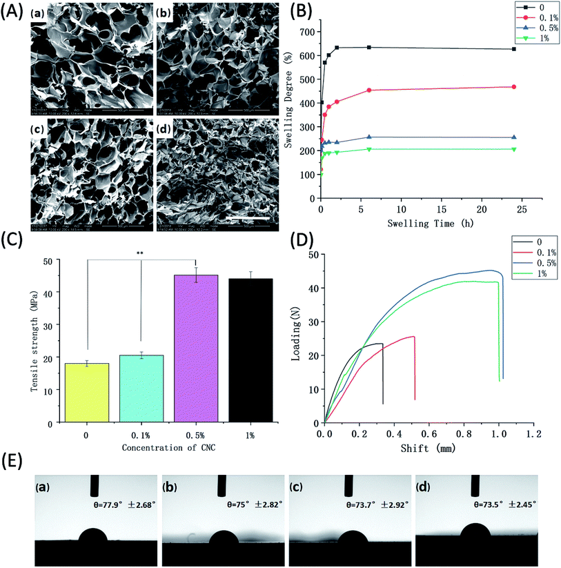
CNC is a tough, biodegradable and renewable polymer which is primarily obtained from cellulose fibers. Owing to its distinctive properties, CNC was utilized in our study and acted as a reinforcing agent in polymer nanocomposites. To further explore the influence of CNC on the properties of scaffold and select its optimum concentration, cross-section morphology observation, water absorption ability, mechanical strength, and contact angle were systemically examined. The SEM images of SA/Ge/CNC scaffolds were presented in Fig. 3A, which showed a porous and entangled network structure. The average pore size and size distributions were measured to study the effect of CNC on the interconnectivity and homogeneity of scaffolds (Table 2). As the concentration of CNC enhanced from 0 to 1%, the pore diameters shrank from 210 ± 40 μm to 120 ± 16 μm. The pore sizes of 0.1% CNC group and 0.5% CNC group were 183 ± 27 μm and 157 ± 31 μm, respectively. The pore sizes displayed a gradual decreasing trend with increasing CNC concentration. Unfortunately, some collapse appeared in the inner structure of SA/Ge/CNC scaffold with 1% CNC, which may attribute to the aggregation of CNC at such concentration. The results suggested that the addition of CNC could improve the pore numbers and diminish the pore sizes.Fig. 3B displayed the water absorption properties of SA/Ge/CNC scaffolds. The results showed that all the samples attained high swelling degree and the SA/Ge scaffold without CNC reached equilibrium swelling within a relatively shorter time. The swelling degree of control group (without CNC) was 627%, while that of 1% CNC group significantly dropped to 207%. The swelling degrees of 0.1% CNC group and 0.5% CNC group were 468% and 256%, respectively. It can be observed from the figure that the incorporation of CNC significantly influenced the swelling behavior of scaffolds and increased concentrations of CNC resulted in the decline of swelling degree. The reason can be considered that the addition of CNC renders the scaffold a denser and tighter network, thus less likely to absorb water.
The mechanical properties of SA/Ge/CNC scaffolds with different CNC contents were summarized in Fig. 3C and D. The results showed that SA/Ge scaffold without CNC had a tensile strength of 18.2 MPa, which enhanced to 20.5 MPa after the addition of 0.1% CNC. It's worth noting that the tensile strength dramatically raised to 45.1 MPa after adding 0.5% CNC into the scaffold. However, the tensile strength of 1% CNC group showed no much significant difference with the 0.5% CNC group (p > 0.05). The results indicated that the mechanical strength of scaffolds showed a tendency to increase after the involvement of CNC. Due to the formation of hydrogen bonding, good interaction and compatibility of CNC with the composite components, CNC can provide significant enhancement in mechanical properties at low volume percentages. The increased amount of CNC in the SA/Ge/CNC scaffolds led to the formation of denser and more highly entangled network, thus resulting in the comparable stiffness improvement.
Contact angle is an essential indicator to judge the hydrophobicity as well as hydrophilicity of materials. A decrease of water contact angle indicates the improvement of hydrophilicity.43 Previous studies have reported that hydrophilic biocomposites could promote the cell proliferation and the wettability is highly related to the barrier properties of materials.44 Here, the contact angles of different SA/Ge/CNC scaffolds were measured to study the impact of CNC on hydrophilicity. As shown in Fig. 3E, contact angles of all the samples were below 90° and consistently at ∼75° on average. The contact angles of control group, 0.1% CNC group, 0.5% CNC group and 1% CNC group were 77.9° ± 2.68°, 75° ± 2.82°, 73.7° ± 2.92°, 73.5° ± 2.45°, respectively. A slight downwards tendency of contact angles could be observed with the enhancement of CNC concentration. There was no significant difference between them. Therefore, CNC has no apparent effect on the hydrophilicity of scaffolds. On the other hand, the results confirmed the hydrophilicity nature of simple SA/Ge and SA/Ge/CNC scaffolds.
In consideration of the microstructure, swelling degree, tensile strength and contact angle characteristics mentioned above, the SA/Ge/CNC scaffold containing 0.5% CNC exhibited superior properties and was selected to further explore its bio-applications for in vitro cytotoxicity assay and in vivo animal experiments.
3.4 Cell study on SA/Ge/CNC scaffold
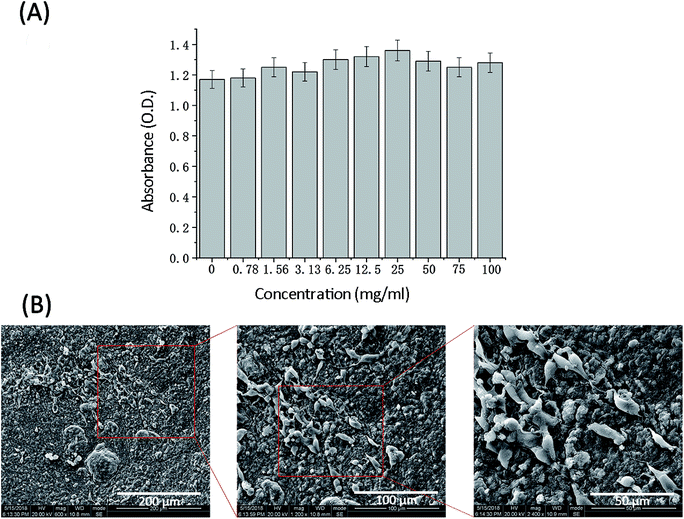
An indispensable factor for tissue engineering materials is the capacity to support cell attachment, spreading and proliferation.23 Non-cytotoxicity and biocompatibility of materials are crucial to further clinical applications. To assess the cytotoxicity of SA/Ge/CNC scaffold, 3T3 cells were incubated in SA/Ge/CNC scaffold leachate with different concentrations for 24 h. The optical density of absorbance (O.D.) which reflects the cell viability was tested through a standard MTT method. As depicted in Fig. 4A, the experimental groups (concentrations of SA/Ge/CNC scaffold leachate = 0.78, 1.56, 3.13, 6.25, 12.5, 25, 50, 75 and 100 mg ml−1) presented higher O.D. values than the control group (concentration of SA/Ge/CNC scaffold leachate = 0 mg ml−1), suggesting that higher number of cells in the scaffold leachate of experimental groups than in the control group. The result indicates that the SA/Ge/CNC scaffold is non-toxic and possesses good cytocompatibility.Subsequently, the morphology, attachment, and proliferation of 3T3 cells on scaffold were investigated. The SEM images of 3T3 cells seeded on the SA/Ge/CNC scaffolds after 3 days were presented in Fig. 4B. It is observed that cells adhered and spread randomly on the SA/Ge/CNC scaffold. Besides, 3T3 cells presented a spindle-like shape and attached with each other, exhibiting an aggregated growth state. The safety of scaffolds is highly related to the good biocompatibility of biopolymers and nanoparticles. According to previous research, the RGD sequence (Arg-Gly-Asp) of gelatin can enhance cell adhesion, differentiation and proliferation.22,45 Additionally, the similar chemical structure between cellulose and SA endows the prepared SA/Ge/CNC scaffolds good compatibility and possibility of cross-linking reaction. Thus, the scaffolds form a better nanostructure for the growth and migration of cells. Briefly, the excellent biological properties of components might contribute to the successful adherence and good spread of 3T3 cells on the scaffold, indicating that SA/Ge/CNC scaffold is a potential candidate for wound regeneration applications.
3.5 Skin regeneration in SD rats
To further evaluate the wound healing performance of the SA/Ge and SA/Ge/CNC scaffolds, two square defects (1.5 cm × 1.5 cm) were modeled on the left and right sides of each SD rat's dorsum. The scaffolds were covered on the right defects (experimental side) as dressings for the wounds, while the left defects were not treated with scaffolds and set as control. According to the scaffolds covered on the experimental sides, all the rats were randomly divided into two groups. Half of them were sutured with SA/Ge scaffolds (SA/Ge group), and the other half were sutured with SA/Ge/CNC scaffolds (SA/Ge/CNC group). Both kinds of scaffolds could be fixed on the four corners of defects with absorbable sutures and resisted the pull force (Fig. 5), which proved the remarkable mechanical strength of scaffolds.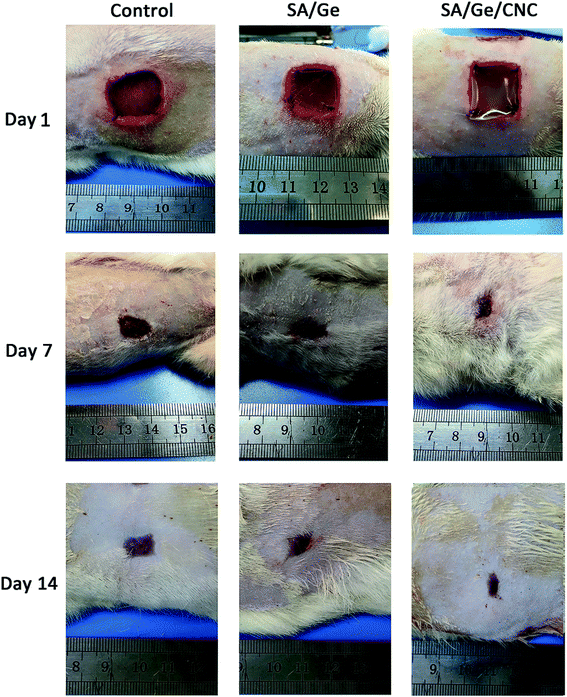 | ||
| Fig. 5 Macroscopic observation of skin wounds in control, SA/Ge, and SA/Ge/CNC groups at 1 days, 7 days, and 14 days after surgery. | ||
On the 7th and 14th days after operation, digital photographs of wounds and the tissue sections were collected to quantitatively assess the area of wound closure, granulation tissue formation, and collagen deposition. Fig. 5 exhibits the macroscopic images of defects in the control, SA/Ge, and SA/Ge/CNC sides on day 1, 7, and 14. During the wound healing progress, no apparent swelling or inflammatory reaction appeared on both sides of the two groups. As observed from photographs, the area of wounds reduced with time in all the groups. Compared to the control sides, the experimental sides of both groups exhibited faster wound healing rates and better skin recovery on day 7 and 14. It can be seen that the re-epithelialization of the experimental side in SA/Ge/CNC group were close to completion on day 14, whereas the same side in the SA/Ge group had not achieved the closure of the wound. At the same time, a large portion of the wound area in the control side was still not completely closed. The rate of re-epithelialization can be ranked in the order of SA/Ge/CNC > SA/Ge > control, revealing the better wound healing efficacy of SA/Ge/CNC scaffolds.
At different time points, the healing area of wounds were calculated according to a standard planimetric method. The wound closure percentages were expressed as the wound size reduction compared to the original area of defects (Fig. 6A). At day 14, the wound closure percentage of SA/Ge side and SA/Ge/CNC side reached 89% and 95%, respectively. In contrast, the control side exhibited the lowest wound closure rate (80%). The healing rate of SA/Ge/CNC side was higher than that of SA/Ge side, which suggested that the SA/Ge/CNC scaffold has a better wound regeneration performance. Meanwhile, the granulation scores and the collage deposition scores were evaluated according to the optical microscope images of H&E staining and Masson's trichrome staining (Fig. 6B and C). The granulation tissue formation and collage deposition play an essential role during the wound healing process and work as indicators to assess the regeneration of epithelium. The control side had the lowest granulation tissue accumulation and loosest collagen fibers on day 7 and 14. Fortunately, the SA/Ge/CNC side demonstrated a better recovery performance with 4.43 of granulation tissue formation score and 89% of collage deposition score after 14 days post-operation. The results indicated the positive function of SA/Ge/CNC scaffold on skin wound healing progress.
 | ||
| Fig. 6 (A) The wound closure, (B) granulation tissue score, (C) collagen content in control, SA/Ge, and SA/Ge/CNC groups at 7 days and 14 days after surgery. | ||
To further evaluate the wounding healing process, the re-epithelialized skin along with normal skin was investigated histologically. The region of neo-epidermis, the formation of new epidermal annexes, and the deposition of collagen are considered as indicators of the early organization and remodeling of tissue. The histological analysis was performed on the basis of the observation of H&E and Masson's trichrome staining results. In the micrographs of H&E staining (Fig. 7), the thickness of the re-epithelialized skin and the infiltration of newly formed cells were clearly visible. At 7 days after treatment, we can find out that the SA/Ge side and SA/Ge/CNC side possessed more continuous and compact epithelium tissue in the upper layer of wounds, whereas re-epithelialization in the control side was less pronounced. There was no obvious difference between the results of SA/Ge side and SA/Ge/CNC side on the 7th day post-injury. But on day 14, more microvessels proliferation and more skin appendage maturation such as hair follicles were observed in the SA/Ge/CNC side compared to the SA/Ge side. Such a difference suggested that wounds treated with SA/Ge/CNC scaffolds were at an accelerated rate of the healing process. The reformation and realignment of collagen are viewed as the major components of tissue remodeling phase during the wounding healing process. The improvement of the newly formed collagen contributed to the increase of tensile strength of tissue.46 From the Masson's trichrome staining sections (Fig. 8), the extent and pattern of the collagen deposition can be compared according to the amount and density of the blue color. The light and dark blue represent the loosely interconnected and densely packed collagen bundles, respectively. At days 7, the accumulation of collagen was loose and randomly organized in the control group. In contrast, the SA/Ge group and SA/Ge/CNC group presented a higher amount of collagen fibers and appeared tightly packed. After 14 days, the difference got more apparent. Compared to the other two groups, images from the SA/Ge/CNC side demonstrated higher collagen density and more compact collagen alignment, where the presence of darker blue was noticed. The results of Masson's trichrome staining proved that SA/Ge/CNC scaffold could exert a positive effect on the dermal re-epithelialization and reconstruction, which were in agreement with the results of gross observation.
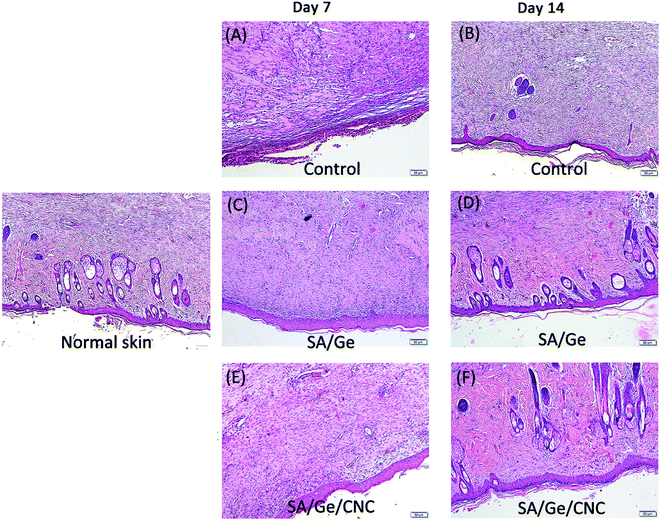 | ||
| Fig. 7 H&E staining images in control, SA/Ge, and SA/Ge/CNC groups at 7 days and 14 days after surgery. The bar corresponds to 50 μm. | ||
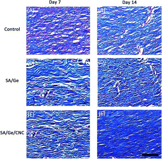 | ||
| Fig. 8 Masson's trichrome staining images in control, SA/Ge, and SA/Ge/CNC groups at 7 and 14 days after surgery. The bar corresponds to 50 μm. | ||
4. Conclusion
In summary, sodium alginate and gelatin scaffolds reinforced by CNC were prepared via a simple and cost-effective method. The optimum ratio of constituents was selected systemically. The microstructure and mechanical strength of SA/Ge scaffolds were significantly improved with the reinforcement of CNC. 3T3 cells can effectively attach and spread on the scaffold, which confirmed its good cyto-compatibility. In the in vivo skin regeneration experiment on SD rats, SA/Ge/CNC scaffolds demonstrated high efficiency to accelerate the recovery of wounds. Taken together, the SA/Ge/CNC scaffold with porosity, appropriate water absorption capacity, excellent mechanical property and biocompatibility is a desirable candidate for skin tissue engineering.Conflicts of Interest
The authors declare no conflicts of interest.Acknowledgements
The authors would like to thank the financial support from the National Natural Science Foundation of China (31600778) and Sichuan University Spark Project (2018SCUH0029). The authors would like to thank Dr Li Chen from Analytical & Testing Center Sichuan University for her help with micro-CT scanning and analysis. All the animal procedures were performed in accordance with the Guidelines for Care and Use of Laboratory Animals of Sichuan University and approved by the Animal Ethics committee of State Key Laboratory of Oral Diseases at Sichuan University.References
- M. P. Sousa, A. I. Neto, T. R. Correia, S. P. Miguel, M. Matsusaki, I. J. Correia and J. F. Mano, Biomater. Sci., 2018, 6, 1962–1975 RSC.
- C. Qi, L. Xu, Y. Deng, G. Wang, Z. Wang and L. Wang, Biomater. Sci., 2018, 6, 2859–2870 RSC.
- J. Liao, Y. Jia, B. Wang, K. Shi and Z. Qian, ACS Biomater. Sci. Eng., 2018, 4, 1029–1036 CrossRef CAS.
- M. Rezvanian, M. Amin and S. F. Ng, Carbohydr. Polym., 2016, 137, 295–304 CrossRef CAS PubMed.
- B. K. Boekema, M. Vlig, L. Olde Damink, E. Middelkoop, L. Eummelen, A. V. Buhren and M. M. Ulrich, J. Mater. Sci.: Mater. Med., 2014, 25, 423–433 CrossRef CAS PubMed.
- R. Quan, X. Zheng, S. Xu, L. Zhang and D. Yang, Stem Cell Res. Ther., 2014, 5, 118 CrossRef PubMed.
- M. Mohiti-Asli, S. Saha, S. V. Murphy, H. Gracz, B. Pourdeyhimi, A. Atala and E. G. Loboa, J. Biomed. Mater. Res., Part B, 2017, 105, 327–339 CrossRef CAS PubMed.
- T. Agarwala, R. Narayana, S. Majia, S. Beheraa, S. Kulanthaivelb, T. Kumar Maitia, I. Banerjeeb, K. Palb and S. Giri, Int. J. Biol. Macromol., 2016, 93, 1499–1506 CrossRef PubMed.
- M. Khamrai, S. L. Banerjee and P. P. Kundu, Carbohydr. Polym., 2017, 174, 580–590 CrossRef CAS PubMed.
- P. Yuan, X. Qiu, R. Jin, Y. Bai, S. Liu and X. Chen, Biomater. Sci., 2018, 6, 820–826 RSC.
- Q. Zhu, M. Jiang, Q. Liu, S. Yan, L. Feng, Y. Lan, G. Shan, W. Xue and R. Guo, Biomater. Sci., 2018, 6, 2472–2486 RSC.
- J. Venkatesan, I. Bhatnagar, P. Manivasagan, K. H. Kang and S. K. Kim, Int. J. Biol. Macromol., 2015, 72, 269–281 CrossRef CAS PubMed.
- Q. Huang, L. Hao, J. Xie, T. Gong, J. Liao and Y. Lin, ACS Appl. Mater. Interfaces, 2015, 7, 20893–20901 CrossRef CAS PubMed.
- D. J. Overstreet, D. Dutta, S. E. Stabenfeldt and B. L. Vernon, J. Polym. Sci., Part B: Polym. Phys., 2012, 50, 881–903 CrossRef CAS.
- J. Boateng, R. Burgos-Amador, O. Okeke and H. Pawar, Int. J. Biol. Macromol., 2015, 79, 63–71 CrossRef CAS PubMed.
- A. Saarai, V. Kasparkova, T. Sedlacek and P. Saha, J. Mech. Behav. Biomed. Mater., 2013, 18, 152–166 CrossRef CAS PubMed.
- L. Yuan, Y. Wu, Q. S. Gu, H. El-Hamshary, M. El-Newehy and X. Mo, Int. J. Biol. Macromol., 2017, 96, 569–577 CrossRef CAS PubMed.
- V. Gopalakannan and N. Viswanathan, Int. J. Biol. Macromol., 2016, 83, 450–459 CrossRef CAS PubMed.
- E.-S. Chan, S.-L. Wong, P.-P. Lee, J.-S. Lee, T. B. Ti, Z. Zhang, D. Poncelet, P. Ravindra, S.-H. Phan and Z.-H. Yim, Carbohydr. Polym., 2011, 83, 225–232 CrossRef CAS.
- D. Singh, A. Tripathi, S. Zo, D. Singh and S. S. Han, Colloids Surf., B, 2014, 116, 502–509 CrossRef CAS PubMed.
- N. El Miri, K. Abdelouahdi, A. Barakat, M. Zahouily, A. Fihri, A. Solhy and M. El Achaby, Carbohydr. Polym., 2015, 129, 156–167 CrossRef CAS PubMed.
- B. Balakrishnan and R. Banerjee, Chem. Rev., 2011, 111, 4453–4474 CrossRef CAS PubMed.
- X. Hu, L. Lu, C. Xu and X. Li, Int. J. Biol. Macromol., 2015, 72, 403–409 CrossRef CAS PubMed.
- K. Song, Y. Yang, S. Li, M. Wu, Y. Wu, M. Lim and T. Liu, Mater. Sci. Eng., C, 2014, 40, 197–203 CrossRef CAS PubMed.
- K. Y. Lee and D. J. Mooney, Prog. Polym. Sci., 2012, 37, 106–126 CrossRef CAS PubMed.
- N. Alemdar, Carbohydr. Polym., 2016, 151, 1019–1026 CrossRef CAS PubMed.
- J. George and S. N. Sabapathi, Nanotechnol., Sci. Appl., 2015, 8, 45–54 CrossRef CAS PubMed.
- H. Dong, K. E. Strawhecker, J. F. Snyder, J. A. Orlicki, R. S. Reiner and A. W. Rudie, Carbohydr. Polym., 2012, 87, 2488–2495 CrossRef CAS.
- K. Madhusudana Rao, A. Kumar and S. S. Han, Int. J. Biol. Macromol., 2017, 101, 165–171 CrossRef CAS PubMed.
- J. R. Yu, J. Navarro, J. C. Coburn, B. Mahadik, J. Molnar, J. H. t. Holmes, A. J. Nam and J. P. Fisher, Adv. Healthcare Mater., 2019, 8, e1801471 CrossRef PubMed.
- H. Sun, K. Feng, J. Hu, S. Soker, A. Atala and P. X. Ma, Biomaterials, 2010, 31, 1133–1139 CrossRef CAS PubMed.
- J. Yan, Y. Miao, H. Tan, T. Zhou, Z. Ling, Y. Chen, X. Xing and X. Hu, Mater. Sci. Eng., C, 2016, 63, 274–284 CrossRef CAS PubMed.
- Y. Wang, Z. Wang, K. Wu, J. Wu, G. Meng, Z. Liu and X. Guo, Carbohydr. Polym., 2017, 168, 112–120 CrossRef CAS PubMed.
- L. Tu, Y. He, H. Yang, Z. Wu and L. Yi, J. Biomater. Sci., Polym. Ed., 2015, 26, 735–749 CrossRef CAS PubMed.
- N. Naseri, B. Deepa, A. P. Mathew, K. Oksman and L. Girandon, Biomacromolecules, 2016, 17, 3714–3723 CrossRef CAS PubMed.
- C. Miao and W. Y. Hamad, Cellulose, 2013, 20, 2221–2262 CrossRef CAS.
- T. Huq, S. Salmieri, A. Khan, R. A. Khan, C. Le Tien, B. Riedl, C. Fraschini, J. Bouchard, J. Uribe-Calderon, M. R. Kamal and M. Lacroix, Carbohydr. Polym., 2012, 90, 1757–1763 CrossRef CAS PubMed.
- N. Lin, C. Bruzzese and A. Dufresne, ACS Appl. Mater. Interfaces, 2012, 4, 4948–4959 CrossRef CAS PubMed.
- K. Song, L. Li, R. Li, M. Lim, P. Liu and T. Liu, Appl. Biochem. Biotechnol., 2014, 173, 838–850 CrossRef CAS PubMed.
- C. Yang, H. Frei, F. M. Rossi and H. M. Burt, J. Tissue Eng. Regener. Med., 2009, 3, 601–614 CrossRef CAS PubMed.
- A. Z. Aroguz, K. Baysal, Z. Adiguzel and B. M. Baysal, Appl. Biochem. Biotechnol., 2014, 173, 433–448 CrossRef CAS PubMed.
- C. Kumar, M. U. H. Joardder, T. W. Farrell, G. J. Millar and M. A. Karim, Drying Technol., 2015, 34, 962–973 CrossRef.
- N. Pal, P. Dubey, P. Gopinath and K. Pal, Int. J. Biol. Macromol., 2017, 95, 94–105 CrossRef CAS PubMed.
- G. Siqueira, J. Bras and A. Dufresne, Biomacromolecules, 2009, 10, 425–432 CrossRef CAS PubMed.
- M. Angelozzi, M. Miotto, L. Penolazzi, S. Mazzitelli, T. Keane, S. F. Badylak, R. Piva and C. Nastruzzi, Mater. Sci. Eng., C, 2015, 56, 141–153 CrossRef CAS PubMed.
- S. Udhayakumar, K. G. Shankar, S. Sowndarya and C. Rose, Biomater. Sci., 2017, 5, 1868–1883 RSC.
| This journal is © The Royal Society of Chemistry 2019 |

