DOI:
10.1039/C9RA05395F
(Paper)
RSC Adv., 2019,
9, 31062-31069
Surface modification of an aramid fiber via grafting epichlorohydrin assisted by supercritical CO2
Received
15th July 2019
, Accepted 14th September 2019
First published on 1st October 2019
Abstract
In order to improve the interface combination property between an aramid fiber (AF) and an epoxy resin matrix, the surface modification of AF with epichlorohydrin (ECH) assisted by supercritical CO2 (ScCO2) was investigated. The fiber surface was characterized by X-ray photoelectron spectroscopy (XPS), scanning electron microscopy (SEM) and dynamic contact angle (DCA) analysis. At the same time, we utilized interfacial shear strength (IFSS) and interlaminar shear strength (ILSS) to characterize the bond strength between the fiber and epoxy resin. An ideal modification effect of the fiber surface was acquired when the fiber treated with ECH in ScCO2 compared with the fiber treated in pure ScCO2. The results showed that ECH could be successfully grafted onto the fiber surface under an anhydrous aluminum chloride (AlCl3) catalyst in ScCO2, and the relative content of oxygen on the fiber surface increased after modification; simultaneously, the morphology of the fiber surface became rougher and the fiber's wettability was upgraded. Finally, the IFSS property of the fiber with the epoxy resin increased, and the ILSS property of the AF-reinforced resin composites was also improved compared with those of the untreated materials.
1. Introduction
An aramid fiber (AF), as a new type of special-purpose synthetic fiber, is widely used in rocket engine housing, bulletproof products, special protective clothing, electronic equipment and other application fields because of its excellent properties such as light weight, ultra-high strength, super elastic modulus, high temperature resistance and excellent insulation property.1,2 The premise that the fiber can be applied well in various fields is because the reinforcing phase and the matrix phase need to form a good interface, which often determines the quality of the composites.3 In the structure of AF-reinforced composites, the fiber responsible for the performance along the fiber axis significantly exists as the main load-bearing part, while the matrix primarily associated with the interlayer property plays a role as a bridge to connect and fix the fiber. However, there are a few active groups on the AF surface and the amide functional group forms a π-conjugation effect on the adjacent benzene ring in the molecular chains.4 At the same time, the fiber possesses a smooth surface due to the high crystallinity and degree of orientation,5 which all result in a poor interface combination between the fiber and the matrix, especially the epoxy resin, seriously affecting the long-term and stable service of the composite materials.6 In other words, the destruction of the AF-reinforced composite products during the service process is mainly attributed to the weak combination between the fiber and the matrix.7
In response to the above drawbacks, many researchers have been trying different methods to modify the AF surface including surface coating, plasma treatment, and chemical grafting, which mainly introduce more polar components or increase the roughness of the fiber surface, achieving satisfactory results.8–12 Among these modification methods, the plasma treatment has a good modification effect in improving the bond properties between AF and the resin by etching the fiber surface, but the reduction of the fiber strength is unavoidable.12 In addition, compared with the modification effect of the surface coating method, the chemical grafting method can result in a chemical bond with the fiber while increasing the functional groups on the fiber surface. This is conducive to the combination between the fiber and resin and obtaining an excellent interface, thereby prolonging the service life of the composite materials. However, the grafting effect of the traditional chemical modification method is not so ideal to modify large quantities of fiber bundles and fabrics due to the poor penetration of the modifier. Therefore, in order to effectively modify the high-volume fiber products and maximally retain the fiber strength, some other modification methods must be considered.
Supercritical CO2 (ScCO2) having the critical temperature and pressure of 31 °C and 7.4 MPa, respectively,13,14 has been confirmed as an environmentally friendly medium for carrying small molecules to the surface or even to the interior of fibers owing to its superior swelling, plasticization and convenient conversion capability between the liquid and gas.15–22 Kong et al. used ScCO2 to carry hexamethylene diisocyanate and toluene-2, 4-diisocyanate to the amorphous region of AF to enhance the degree of crystallization of AF.15,23 Yoshida et al. proposed a new electroplating method of nickel in an emulsion of ScCO2 to enhance the uniformity of the plated film.24 In view of these, ScCO2 can be tentatively used as a reaction medium for the uniform modification of the fiber surface without reducing the fiber strength. Epichlorohydrin (ECH) is an important oxygen-containing organic synthesis raw material used primarily in the manufacture of epoxy resins and as a modifier. ECH contains a large number of oxygen-containing functional groups, which can be grafted onto the benzene ring to increase the activity and roughness of the fiber surface. Wu and co-workers showed that 27.88% improvement in the interlaminar shear strength (ILSS) property of F-12 AF-reinforced E-51 epoxy resin composites could be achieved by ECH grafting using the traditional chemical method. Among them, the fibers were previously treated with a mixture of potassium hydroxide and ethanol to break the fiber molecule chains and then reacted with ECH.25 Liu and co-workers showed that the ILSS property of the AF-reinforced epoxy matrix composites increased by 50% when the fibers were treated with ECH using Friedel–Crafts alkylation;26 it is a reaction in which a hydrogen atom on the aromatic ring is replaced by an alkyl group of the haloalkane in the presence of a Lewis acid such as anhydrous aluminum trichloride (AlCl3). The related literature shows that ScCO2 can dissolve most organic compounds including heptachlor epoxide27,28 and the reaction activity in the ScCO2 atmosphere is more active under low temperatures than the chemical reaction at high temperatures due to the strong diffusion ability of ScCO2.29 In order to improve the uniformity and continuity of the grafting effect, ScCO2 was selected as a modification medium.
In this article, we tentatively used ECH under the catalysis of AlCl3 in ScCO2 to modify the surface of the AF bundles and fabrics in the reactor, providing ideas for modifying large quantities of fiber products and thereby increasing the interlaminar properties of the composite materials in a broad field. In order to rule out the influences of pure ScCO2 on the modification effect of the fiber surface treated with ECH in ScCO2, we simultaneously carried out a parallel reaction of fibers treated in pure ScCO2.
2. Materials and methods
2.1 Materials
AF bundles made up of 1000 monofilaments with linear density of 3.56 dtex and diameter of 16.65 μm as well as AF-weaved fabrics (Style Mt-9120, 200 g m−2) with ply of 0° and 90° were provided by the Zhonglan Chenguang Chemical Research Institute (Sichuan, China). CO2 gas with purity of 99.99% was purchased from Shanghai Jiali Gas Co., Ltd. (Shanghai, China). Acetone (≥99.50%), AlCl3 (analytical grade) and ECH with a boiling point of 117.9 °C were all acquired from the Sinopharm Chemical Reagent Beijing Co., Ltd. (Beijing, China). A resin system containing the epoxy resin E-51 and the corresponding curing agent M-36 with a stoichiometric mass ratio of 100![[thin space (1/6-em)]](https://www.rsc.org/images/entities/char_2009.gif) :
:![[thin space (1/6-em)]](https://www.rsc.org/images/entities/char_2009.gif) 25 and curing system of 120 °C and 2 h was obtained from Shanghai Fangye Chemical Co., Ltd. (Shanghai, China).
25 and curing system of 120 °C and 2 h was obtained from Shanghai Fangye Chemical Co., Ltd. (Shanghai, China).
2.2 Modification process and experimental principle of AF surface
A schematic diagram of the device of the AF surface treated with ECH in the ScCO2 reactor is shown in Fig. 1a. The entire process can be summarized as follows: first, the fibers were washed repeatedly with acetone through a circulating condensing device at 80 °C for 12 h, followed by drying in a vacuum oven at 80 °C until there were no changes in the fiber quality. Next, 2 g of the cleaned fiber bundles and ten layers of fabrics as well as 0.1 g of AlCl3 as the catalyst were tightly fixed onto every platform (Fig. 1b) connected to the stir bar of the reactor with a volume of 10 L customized by Tianjin Yantu Experimental Instrument Development Co., Ltd. (Tianjin, China). Then, about 2 MPa of CO2 gas was transported from the CO2 cylinder to the reactor to remove the air by a booster pump with a pressurization ratio of 64 when the temperature of the reactor rose to 120 °C and exhausted the gas after a while; this operation was repeated twice. After the air in the reactor was completely discharged, 50 ml of ECH was sent into the reactor with a syringe through the feed port on the reaction vessel; this was followed by closing the feed port, starting the stir bar to move at a speed of 300 rpm to make ScCO2 flow in the reactor and beginning to pressurize the pressure to 10 MPa when the temperature rose to 120 °C again. Finally, the reaction was carried out for 2 h by relying on ScCO2 to drive ECH to the fiber surface when the temperature and pressure in the reactor were maintained at 120 °C and 10 MPa, respectively. After the reaction, the samples were washed with acetone at 60 °C for 40 min in an ultrasonic cleaning machine, followed by drying in a vacuum oven at 80 °C for 2 h; then, they were collected for various characterizations. Fig. 2 shows the diagram of the modification process of the AF surface with ECH in the ScCO2 medium. Fig. 3 shows the mechanism of the main reaction of ECH grafted onto the fiber surface under the catalysis of AlCl3, from which we inferred that H on the benzene ring connected to N–H of the molecular chain was substituted by an epoxy alkyl functional group from ECH, thereby providing an oxygen-containing functional group on the fiber surface.
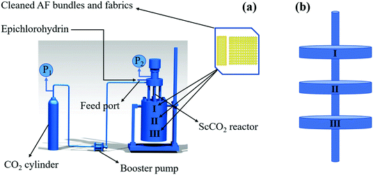 |
| | Fig. 1 Schematic diagram of the device containing AF surfaces treated with ECH in an ScCO2 reactor (a) and the platform to fix the fiber (b). | |
 |
| | Fig. 2 Process diagram of the modification of the AF surface with ECH in ScCO2 medium. | |
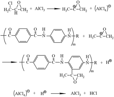 |
| | Fig. 3 Mechanism of the main reaction of ECH grafted onto the AF surface using the catalyst AlCl3. | |
2.3 Preparation of micro-debonding test samples and AF-reinforced composites
Several single AFs were randomly selected from the fiber bundles and glued to a rectangular metal frame with an adhesive. Then, a trace amount of the E-51 resin system was dropped onto the monofilament and cured in a vacuum oven at 120 °C for 2 h. The AF-reinforced resin composites were prepared by the vacuum-assisted resin infusion molding technology30 with the same curing process as the resin system.
2.4 Characterization
The functional groups and elemental analysis of the fiber surface were examined by an X-ray photoelectron spectrometer (XPS, Escalab 250Xi, Thermo Scientific, USA) with the excitation source and standard source of Mg and Kα rays, respectively, at a voltage of 8.0 kV and power of 240 W. The morphologies of the fiber surface and fracture cross-section of the composites were observed by scanning electron microscopy (SEM, Hitachi S-4700, Japan). All samples were pre-coated with a layer of gold and the voltage and current were adjusted to 12.5 kV and 10 μA, respectively, during the test. The dynamic contact angle (DCA) and surface free energy of the fiber surface were measured with the test media of deionized water and diiodomethane by a CA meter (DCAT21, Data-Physics Instrument, Germany) at an ambient temperature. The DCA and surface free energy including the dispersive and polar components were calculated based on the Wilhelmy's equation31 and the Owens–Wendt model,32 respectively. The interfacial shear strength (IFSS) property of the fiber with the resin system was tested using a setup in which the epoxy system droplet was placed between two metal blades in advance, as shown in Fig. 4, and stretched to obtain the maximum load at a loading speed of 0.06 mm min−1. The IFSS property of the fiber with the resin system was calculated using eqn (1):33| |  | (1) |
here, F is the maximum load during the test (N), D is the fiber's diameter (mm), and L is the embedded length (μm).
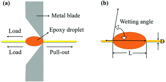 |
| | Fig. 4 . Schematic diagram of the pull-out test setup of single AF (a) and microsphere coating size and fiber diameter (b). | |
The ILSS property of the AF-reinforced composites was tested through a universal test machine (5960, Instron, USA) by a three-point bending technology with a span length of 16 mm and cross-head speed of 10 mm min−1 according to ASTM D2344 standard.34 The ILSS property of the AF-reinforced composites was calculated using eqn (2):
| |  | (2) |
here,
P is the maximum load in the test (N), and
b and
h are the width (mm) and thickness (mm) of each sample before the test, respectively.
3. Results and discussion
3.1 XPS analysis
Fig. 5 reveals the XPS spectra of the untreated and modified AF surfaces, and the corresponding chemical composition of the fiber surface is presented in Table 1. The peaks at the binding energies of 285, 400 and 532 eV, corresponding to carbon, nitrogen and oxygen, represent the main elemental composition of the untreated AF surface.35 There were no significant changes in the chemical composition of the fiber surface when the fibers were treated with pure ScCO2, as summarized in Table 1, indicating that pure ScCO2 had no obvious modification effects on the fiber surface. After treatment with ECH in ScCO2, a new binding energy peak appeared at 201 eV, corresponding to chlorine. This is because the Friedel–Crafts reaction is a reversible reaction, allowing some ECH species to remain on the fiber surface after the reaction. Furthermore, we observed increase in the relative concentrations of oxygen and the O/C ratio from 12.68% and 0.164 to 22.47% and 0.317, respectively, after the fiber was treated with ECH in ScCO2, thereby enhancing the activity of the fiber surface, which was beneficial for bonding with the resin system.12,36–38
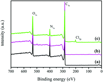 |
| | Fig. 5 XPS spectra of the related AF surfaces: (a) the untreated AFs, (b) AFs treated in pure ScCO2 and (c) AFs modified with ECH in ScCO2. | |
Table 1 Elemental analysis of the AF surface at different modification conditions
| Samples |
Chemical composition (at. mol%) |
Atomic ratio |
| C |
O |
N |
Cl |
N/C |
O/C |
| Untreated AFs |
77.49 |
12.68 |
9.79 |
0.04 |
0.126 |
0.164 |
| AFs in ScCO2 |
76.54 |
13.52 |
9.92 |
0.02 |
0.130 |
0.177 |
| AF-ECP in ScCO2 |
70.84 |
22.47 |
6.33 |
0.36 |
0.089 |
0.317 |
Furthermore, in order to observe the changes in the functional groups before and after modification, Fig. 6 presents the C1s peak spectra of the untreated and modified AF surfaces. The C1s peak spectrum of the untreated AF surface indicates the presence of 70.25% C–C, 15.74% C–N and 14.01% C![[double bond, length as m-dash]](https://www.rsc.org/images/entities/char_e001.gif) O at 284.8, 285.9 and 288.0 eV, respectively, which are the main functional groups on the AF surface, as shown in Fig. 6a. There were no significant changes in the functional groups of the fiber surface treated without ECH in ScCO2, as depicted in Fig. 6b. However, as we can see from Fig. 6c, the new functional group C–O with the content of 13.75% and a peak at 286.3 eV implied that ECH was successfully grafted onto the fiber surface assisted by ScCO2. These changes correspond to the improvement in the O/C ratio given in Table 1.
O at 284.8, 285.9 and 288.0 eV, respectively, which are the main functional groups on the AF surface, as shown in Fig. 6a. There were no significant changes in the functional groups of the fiber surface treated without ECH in ScCO2, as depicted in Fig. 6b. However, as we can see from Fig. 6c, the new functional group C–O with the content of 13.75% and a peak at 286.3 eV implied that ECH was successfully grafted onto the fiber surface assisted by ScCO2. These changes correspond to the improvement in the O/C ratio given in Table 1.
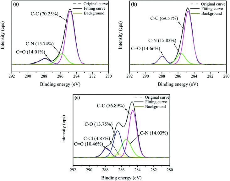 |
| | Fig. 6 The C1s peak spectra of the surfaces of (a) the untreated AFs, (b) AFs treated in pure ScCO2 and (c) AFs modified with ECH in ScCO2. | |
3.2 SEM analysis
The surface morphology of AF before and after modification was examined by SEM, as depicted in Fig. 7. The untreated AF surface was rather smooth, as shown in Fig. 7a, obviously leading to poor interfacial adhesion with the resin system. It is essential to emphasize that the presence of ScCO2 made the fiber surface smoother, which was verified from Fig. 7b. This was mainly due to the fact that ScCO2 could further extract the impurities from the fiber surface.14 An obvious morphology variation in the fiber surface was observed after treatment with ECH in ScCO2, as depicted in Fig. 7c. Specifically, some mild grooves and gibbous particles existed on the modified fiber surface, which had the advantage of creating a mechanical bite between the fiber and resin system to enhance the bond property between them.
 |
| | Fig. 7 The surface morphologies of (a) the untreated AFs, (b) AFs treated in pure ScCO2 and (c) AFs modified with ECH in ScCO2. | |
3.3 DCA analysis
DCA is an important parameter to describe the wetting ability of the related fiber surfaces. Fig. 8a and b show the CA and surface free energy of the untreated and modified AF surfaces, respectively. No obvious changes in CA and surface free energy were found when the fibers were treated without ECH in ScCO2, which corresponded to the XPS and SEM results. CA dramatically decreased from 76.46° to 46.47° for water and from 37.46° to 26.24° for diiodomethane after modification with ECH in ScCO2. In addition, the polar and dispersive surface energies of the fiber surface increased to 10.48 and 52.48 mJ m−2, respectively, in comparison to those of the untreated materials: 6.67 and 41.35 mJ m−2, respectively. These results show the possibility of the improvement in the contact areas and wettability between AF and the resin system.
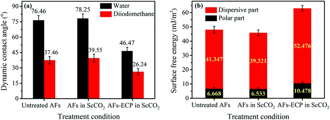 |
| | Fig. 8 (a) The CA and (b) surface free energy of the untreated and modified AF surfaces. | |
3.4 IFSS property analysis
During the service process of composite materials, stress is transferred between the matrix and reinforcement through their interfaces. Therefore, the bond strength between the interfaces directly affects the performance of composites. The single fiber micro-debonding test is often used to evaluate the IFSS property between the fiber and resin system. The IFSS properties of the untreated and modified AFs with the resin system are shown in Fig. 9a. Compared with the IFSS property of the untreated AFs, the IFSS property of the fibers treated with ECH in ScCO2 improved by 45.84%, indicating an increase in the bond property between the fiber and the resin system. This was due to the rougher fiber surface and improvement in the oxygen-containing functional groups on the fiber surface. It is conceivable that the IFSS property of the fibers modified only with ScCO2 was lower than that of the untreated fibers, which was consistent with previous characterizations of the fiber surface. In addition, in order to verify the uniformity of the modification effect of the fiber surface modified with ECH in ScCO2, we randomly selected the fibers at three different positions in the reactor for the IFSS test, as shown in Fig. 1, and the IFSS properties are shown in Fig. 9b. We could conclude that the IFSS values of the modified fibers at three positions, namely, the upper, middle and lower portions of the reactor were very similar, indicating that the modification effect of the fiber surface modified with ECH in ScCO2 was very uniform.
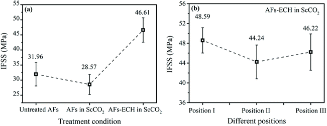 |
| | Fig. 9 The IFSS property of the untreated and modified AFs (a) and the IFSS property of AFs modified with ECH in ScCO2 at different positions in the reactor (b). | |
3.5 ILSS property analysis
Since the poor adhesion between the fiber and the resin system is often the main cause of damage in composites, the ILSS property is usually used to characterize the degree of adhesion between the composite layers to evaluate the interlaminar property of the composites. Fig. 10a shows the ILSS property of the AF-reinforced composites and Fig. 10b presents the corresponding typical load-deflection of the composites. Compared with the ILSS property of the untreated AF-reinforced composites, the ILSS property of the AF-ECH-reinforced composites improved by 68.01%, which indicated an increase in the bond property between the fiber and the resin system. The increase in the bond property can be explained from the following two aspects: first, the improvement in the relative oxygen content and the O/C ratio indicated an increase in the oxygen-containing groups on the fiber surface, thereby increasing the activity of the fiber surface, which increased the bond property between the fiber and the resin system. Second, the surface roughness of AF-ECH increased, which added mechanical bites between the fiber and the resin system to some extent. It could be seen that ScCO2 was mainly present in the form of a kind of medium for carrying ECH to the fiber surface in the case of dynamic fluids, therefore forming an atmosphere full of ECH to modify the AF surface uniformly.
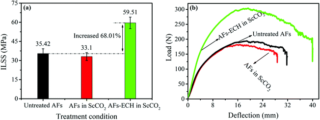 |
| | Fig. 10 The ILSS property (a) and the typical load-deflection (b) of the untreated and modified AF-reinforced resin composites. | |
3.6 SEM images of composite fracture surfaces
Fig. 11 shows the SEM images of the cross-section fracture surface of the composites after interlaminar shear failure before and after the surface modification of fibers. It can be seen from Fig. 11a that there are almost no resins bonded on the fiber surface at the cross-section fracture surface of the untreated AF-reinforced composites, indicating that the fiber and the resin system are separated during the fracture of the composite layer. This corresponded to the fact that the fiber surface was very smooth and not favorable for bonding with the resin. This fracture condition indicated that the fibers did not enhance the composite during the fracture process. A similar situation was also acquired when the fibers were treated in pure ScCO2, as shown in Fig. 11b. In contrast to this, a large amount of resin remained at the cross-section fracture surface during the destruction process of the composite layers when the fibers were modified with ECH in ScCO2, as shown in Fig. 11c, indicating that a good interface between the fiber and the resin system was formed. The fracture condition indicated that the fibers had a reinforcing effect on the composite materials and enhanced the ILSS performance of the composite materials.
 |
| | Fig. 11 The fracture cross-section surface of composites with AFs modified at different conditions: (a) the untreated AFs, (b) AFs treated in pure ScCO2 and (c) AFs modified with ECH in ScCO2. | |
4. Conclusions
This paper proposed a method for grafting ECH on the AF surface using the AlCl3 catalyst assisted by ScCO2 in a reactor. The surface modification made the fiber surface rougher and more active to form a better interface for combining with the resin system. In addition, an increase of 45.84% in the IFSS property and an increase of 68.01% in the ILSS property both powerfully illustrated that it was an effective way to improve the interface combination between AF and the resin system. Moreover, as a green and environmentally friendly medium, ScCO2 can simultaneously modify fiber products in a wide range.
Conflicts of interest
There are no conflicts to declare.
Acknowledgements
This work was supported by the State Key Laboratory for Modification of Chemical Fibers and Polymer Materials, Donghua University (No. LK1602).
References
- W. Tian, Q. Teng, Y. Shi, L. He and X. Tuo, Mater. Lett., 2017, 202, 158–161 CrossRef CAS.
- B. A. Patterson, M. H. Malakooti, J. Lin, A. Okorom and H. A. Sodano, Compos. Sci. Technol., 2018, 161, 92–99 CrossRef CAS.
- G. Qi, B. Zhang and S. Du, Composites, Part A, 2018, 121, 549–557 CrossRef.
- H.-D. Zheng, J. Zhang, J. Yan and L.-J. Zheng, RSC Adv., 2017, 7, 3470–3479 RSC.
- S. Ifuku, H. Maeta, H. Izawa, M. Morimoto and H. Saimoto, RSC Adv., 2014, 4, 40377–40380 RSC.
- C. Zheng, D. Hong, D. Yu, J. Chan, C. Meng, L. Luo and X. Liu, Appl. Surf. Sci., 2018, 434, 473–480 CrossRef.
- H. Cen, Y. L. Kang, Z. K. Lei, Q. H. Qin and W. Qiu, Compos. Struct., 2006, 75, 532–538 CrossRef.
- C. Zheng, H. Yutong, L. Longbo and L. Xiangyang, Mater. Lett., 2018, 233, 102–106 CrossRef.
- B. A. Patterson and H. A. Sodano, ACS Appl. Mater. Interfaces, 2016, 8, 33963–33971 CrossRef CAS.
- Y. Dan, S. Mu, L. Liu and W. Wei, Colloids Surf., A, 2015, 483, 53–59 CrossRef.
- J. R. Chen, Y. F. Zhu, Q. Q. Ni, Y. Q. Fu and X. Fu, Appl. Surf. Sci., 2014, 321, 103–108 CrossRef CAS.
- W. Fan, H. Tian, H. Wang, T. Zhang and S. Wang, Polym. Test., 2018, 72, 147–156 CrossRef CAS.
- S. Asai, Y. Shimada, Y. Tominaga and M. Sumita, Macromolecules, 2005, 38, 6544–6550 CrossRef CAS.
- A. Cooper, J. Mater. Chem., 2000, 10, 207–234 RSC.
- H. Kong, C. Teng, X. Liu, J. Zhou and M. Yu, RSC Adv., 2014, 4, 20599–20604 RSC.
- X. Wang, W. Cui, C. Meng and Q. Xu, Mater. Lett., 2017, 201, 129–132 CrossRef CAS.
- J. Yue, Q. Xu, Z. W. Zhang and Z. M. Chen, Macromolecules, 2007, 40, 8821–8826 CrossRef CAS.
- X. Zhao, K. Hirogaki, I. Tabata, S. Okubayashi and T. Hori, Surf. Coat. Technol., 2006, 201, 628–636 CrossRef CAS.
- M. Belmas, I. Tabata, K. Hisada and T. Hori, J. Appl. Polym. Sci., 2011, 119, 2283–2291 CrossRef CAS.
- N. Martinez, K. Hisada, I. Tabata, K. Hirogaki, S. Yonezawa and T. Hori, J. Supercrit. Fluids, 2011, 56, 322–329 CrossRef CAS.
- H. J. Kong, P. Yang, C. Q. Teng and M. H. Yu, RSC Adv., 2015, 5, 58916–58920 RSC.
- X. Jing, Y. Han, L. Zheng and H. Zheng, J. CO2 Util., 2018, 27, 289–296 CrossRef CAS.
- H. Kong, Q. Xu and M. Yu, Polymers, 2019, 11, 1110–1123 CrossRef CAS.
- H. Yoshida, M. Sone, H. Wakabayashi, H. Yan, K. Abe, X. T. Tao, A. Mizushima, S. Ichihara and S. Miyata, Thin Solid Films, 2004, 446, 194–199 CrossRef CAS.
- J. Wu and X. H. Cheng, J. Appl. Polym. Sci., 2006, 102, 4165–4170 CrossRef CAS.
- T. M. Liu, Y. S. Zheng and J. Hu, J. Appl. Polym. Sci., 2010, 118, 2541–2552 CrossRef CAS.
- Y. C. Ling, H. C. Teng and C. Cartwright, J. Chromatogr. A, 1999, 835, 145–157 CrossRef CAS.
- B. Li, W. Guo, W. Song and E. D. Ramsey, J. Chem. Eng. Data, 2016, 61, 2128–2134 CrossRef CAS.
- M. Álvaro, D. Das, M. Cano and H. Garcia, J. Catal., 2003, 219, 464–468 CrossRef.
- Y. Gu, X. Tan, Z. Yang, L. Min and Z. Zhang, Mater. Des., 2014, 56, 852–861 CrossRef CAS.
- Z. Guo, D. Ding, X. Yan, X. Zhang, Y. D. Huang, S. Wei, L. Xing, Q. Zhang, Z. Wu and J. Guo, J. Mater. Chem. A, 2014, 2, 18293–18303 RSC.
- L. Chen, Y. Du, Y. Huang, P. F. Ng and B. Fei, Compos. Sci. Technol., 2016, 129, 86–92 CrossRef CAS.
- W. W. Zhou, G. Yamamoto, Y. Fan, H. Kwon, T. Hashida and A. Kawasaki, Carbon, 2016, 106, 37–47 CrossRef CAS.
- Z. Jiang, A. Imam, R. Crane, K. Lozano, V. N. Khabashesku and E. V. Barrera, Compos. Sci. Technol., 2007, 67, 1509–1517 CrossRef.
- Z. Cheng, P. Wu, B. Y. Li, T. Chen, Y. Liu, M. M. Ren, Z. M. Wang, W. C. Lai, X. Wang and X. Y. Liu, Appl. Surf. Sci., 2016, 384, 480–486 CrossRef CAS.
- Z. Shu-Hui, H. E. Guo-Qiang, L. Guo-Zheng, H. Cui, W. Zhang and B. Wang, Appl. Surf. Sci., 2010, 256, 2104–2109 CrossRef.
- Y. H. Zhang, Y. D. Huang, L. Liu and K. L. Cai, Appl. Surf. Sci., 2008, 254, 3153–3161 CrossRef CAS.
- W. Jing, C. Ping, C. Lu, Y. Qi, L. Wei and R. Rong, Compos. Interfaces, 2018, 25, 1–13 CrossRef.
|
| This journal is © The Royal Society of Chemistry 2019 |
Click here to see how this site uses Cookies. View our privacy policy here.  Open Access Article
 a and
Muhuo
Yu
 *a
*a
![[thin space (1/6-em)]](https://www.rsc.org/images/entities/char_2009.gif) :
:![[thin space (1/6-em)]](https://www.rsc.org/images/entities/char_2009.gif) 25 and curing system of 120 °C and 2 h was obtained from Shanghai Fangye Chemical Co., Ltd. (Shanghai, China).
25 and curing system of 120 °C and 2 h was obtained from Shanghai Fangye Chemical Co., Ltd. (Shanghai, China).


![[double bond, length as m-dash]](https://www.rsc.org/images/entities/char_e001.gif) O at 284.8, 285.9 and 288.0 eV, respectively, which are the main functional groups on the AF surface, as shown in Fig. 6a. There were no significant changes in the functional groups of the fiber surface treated without ECH in ScCO2, as depicted in Fig. 6b. However, as we can see from Fig. 6c, the new functional group C–O with the content of 13.75% and a peak at 286.3 eV implied that ECH was successfully grafted onto the fiber surface assisted by ScCO2. These changes correspond to the improvement in the O/C ratio given in Table 1.
O at 284.8, 285.9 and 288.0 eV, respectively, which are the main functional groups on the AF surface, as shown in Fig. 6a. There were no significant changes in the functional groups of the fiber surface treated without ECH in ScCO2, as depicted in Fig. 6b. However, as we can see from Fig. 6c, the new functional group C–O with the content of 13.75% and a peak at 286.3 eV implied that ECH was successfully grafted onto the fiber surface assisted by ScCO2. These changes correspond to the improvement in the O/C ratio given in Table 1.


