 Open Access Article
Novel porous organocatalysts for cycloaddition of CO2 and epoxides†
Joel M. Kolle and
Abdelhamid Sayari *
*
Centre for Catalysis Research and Innovation (CCRI), Department of Chemistry, University of Ottawa, Ottawa, Ontario, Canada K1N 6N5. E-mail: Abdel.Sayari@uottawa.ca
First published on 7th August 2019
Abstract
Three classes of organosilicas (DMO, OMOs and PMOs) containing immobilized multi-hydroxyl bis-(quaternary ammonium) iodide salts were prepared and tested in the cycloaddition of CO2 and epoxides. Owing to its higher surface area, pore volume and optimum nucleophilicity of the iodide ion, OMO-2 with two hydroxyl groups was found to be the most active catalyst. For substrates that are easy to activate such as propylene oxide, 1,2-epoxybutane and epichlorohydrin, excellent yields and selectivities were obtained under mild reaction conditions (0.5 MPa CO2, 50 °C and 10–15 h). Moreover, OMO-2 showed very good catalytic properties (yield ≥ 93% and selectivity ≥ 98%), and excellent chemical and textural stability in the synthesis of 1,2-butylene carbonate over 5 cycles.
Introduction
Among greenhouse gases (GHGs), carbon dioxide (CO2) is the main anthropogenic contributor to global warming and climate change.1,2 Carbon capture is recognized as one of the most promising strategies to mitigate the adverse effects of CO2 emissions.3,4 Previously viewed largely as an industrial waste product, CO2 is increasingly being valued as a cheap, readily available and non-toxic C1 source for the synthesis of chemicals and fuels.5,6 Accordingly, CO2 utilization is gaining popularity as a complementing tool to CO2 capture and sequestration towards GHG mitigation. However, the inherent thermodynamic stability of CO2 leads to low reactivity. As such, high CO2 pressure and reaction temperature are generally required for its transformation. Nonetheless, combining CO2 with highly reactive substrates such as epoxides and aziridines, in the presence of suitable catalysts, provides a pathway to overcome this energy barrier. The catalytic conversion of CO2 and epoxides to cyclic carbonates (CCs) is one of many reactions using CO2 as an alternative C1 feedstock. Application of CCs as aprotic polar solvents, active pharmaceutical ingredients, and monomers in the production of fine chemicals makes them an important group of organic materials in the chemical industry. In the generalized mechanism for the synthesis of CCs, regioselective CO2 insertion is achieved by a combination of epoxide activation by Y through oxygen atom coordination and ring-opening by a nucleophile, X− (Scheme 1).A variety of homogeneous catalysts such as ionic liquids7 and metal complexes;8 immobilized catalysts including supported ionic liquids,7 and traditional heterogeneous catalysts9 were reported to be active towards CO2 cycloaddition. On their own, the last group of catalysts showed low reactivity, and as such received less attention compared to free and immobilized homogeneous catalysts. The latter may consist of a single catalytic component, or a combination of a catalyst and a co-catalyst.8 Examples of one-component catalyst include tributylpropylammonium iodide immobilized on silica,10 quaternary ammonium11 and phosphonium12 salts. Two-component catalysts include benzylbromide/DMF,13 tetrabutylammonium salt/EDTA,14 and polymer-supported quaternary onium salts/aqueous solutions of metal salts.15 These catalysts are not highly popular as they increase the complexity of the process, leading to tedious catalyst separation/recovery and product purification steps. Accordingly, to achieve simplified and cost-effective chemical processes, one-component catalysts are preferred.
One-component catalysts can be mono- or bifunctional in nature. Mono-functional catalysts such as alkyl quaternary ammonium16 or phosphonium17 halides play a single role, which consists of opening the epoxide ring, leading to the insertion of CO2. These extensively investigated catalysts were found to exhibit good to excellent yields in the cycloaddition of CO2 and epoxides.18,19 Moreover, one-component bifuntional homogeneous or immobilized catalysts may contain specific functional groups, such as –COOH, –NH2 and –OH or metals (e.g. Zn, Co and Al). Bifunctionality implies that the catalytic material plays two roles in the course of the reaction, namely; (1) activation of the epoxide by the functional groups,20 rendering it more susceptible to undergo cycloaddition – Y in Scheme 1, and (2) opening of the epoxide ring by the halide ion,21 similar to the mono-functional catalysts, X− in Scheme 1. The above functional groups activate the epoxides via hydrogen bonding, while epoxide activation by metal occurs through the formation of metalalkoxides via Lewis acid interactions.22,23 Examples of metal-free one-component bifunctional catalysts include free and supported hydroxylalkyl ammonium salts11 or phosphonium17 salts. Regardless of the design, type or functionality of the catalyst, the ring opening of all epoxides requires a nucleophile. The iodide ion was reported as one of the most efficient owing to its exceptional leaving group ability, stemming from its bulky nature and lower electronegativity.
In terms of sustainable and low-cost processes, highly active metal-free one-component bifunctional catalysts with stable active sites and easy reusability are attractive. Many such catalysts, covalently anchored onto a variety of solid materials were reported in the literature.24 In some cases, these hybrid solids demonstrate similar or even better activities compared to their homogeneous counterparts.17,25 Porous inorganic solids such as mesoporous SBA-15 silica26,27 was used as support for one-component porous hybrid solid (PHS) catalysts for the synthesis of cyclic carbonates. Compared to organic supports such as polystyrene, they offer better thermal and mechanical stability, enhanced chemical interaction between the support and the active organic species and high loading of active sites, thereby enhancing production. Moreover, mesoporous inorganic supports alleviate molecular traffic within the pore system, which could enhance both the rate and selectivity of the reaction.
The main preparation method for PHS entails post-synthesis surface functionalization of a silica; typically through grafting of an aminosilane or phosphine–silane, followed by quaternization to afford an immobilized quaternary ammonium or phosphonium salt – Scheme 2a. Often, such organosilicas consist of a disordered distribution of the organic moieties; hence these solids may be referred to as disordered mesoporous organosilicas (DMO). Alternatively, the co-condensation of a silica network former (e.g. TEOS or TMOS) and an organosilica precursor (organotrialkoxysilanes, bridged- or poly-silsesquioxanes) over a structure directing agent is a one-pot synthesis method to obtain ordered mesoporous organosilicas (OMOs) – Scheme 2b. Furthermore, a distinctive group of mesoporous organocatalysts, with a unique homogeneous distribution and high loading of covalently linked organic functionalities within the silica framework are periodic mesoporous organosilicas (PMOs). These materials are derived from the hydrolytic sol–gel polycondensation of organic bridged-silsesquioxanes (R[Si(OR′)3]n; n ≥ 2) in the presence of surfactant templates without addition of silica precursors – Scheme 2c.
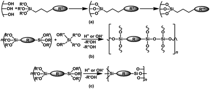 | ||
| Scheme 2 Synthesis of (a) DMO via surface grafting and quaternization (b) OMO via the co-condensation route (c) periodic mesoporous organosilicas – PMO. | ||
Significant progress in the synthesis of CCs from CO2 and epoxides over mesoporous organocatalysts derived by the grafting of aminosilane followed by quaternization (Scheme 2a) has been reported in a number of reviews.7,28 Although OMOs containing ammonium halides,29,30 and PMOs containing melamine31 and urea32 moieties were reported as active catalysts in the synthesis of CCs, OMOs and PMOs received noticeably less attention compared to DMOs. Considering the higher surface area of OMOs compared to DMOs, and the significantly higher organic content achievable with PMOs, organocatalysts with greater surface area and active sites can be obtained from OMOs and PMOs respectively. If such active sites can be readily accessed, a significant enhancement in catalytic performance (i.e. higher reaction rates, selectivity and yield) can be expected. In addition, higher active site density is expected to enhance catalytic activity. In this sense, homogeneous33 and heterogeneous34 organocatalysts containing two active sites per molecule were found to be more effective than those containing only one. In this contribution, we present four groups of novel immobilized multi-hydroxyl bis-(quaternary ammonium) salts prepared via three routes: (1) grafting of a bridged-SQ on silicas, followed by quaternization, (2) co-condensation of (i) bridged-SQ and (ii) poly-SQ with TEOS, and (3) PMOs derived from (i) bridge-SQ and (ii) poly-SQ. Furthermore, their activity in the synthesis of CCs from CO2 and epoxides under mild reaction conditions was discussed. The reusability of the most active catalyst was also investigated to better understand the catalyst performance (yield and selectivity), chemical stability (resistance to leaching) and structural stability (textural properties) with reuse.
Experimental
Materials
N,N′-Bis(2-hydroxyethyl)-N,N′-bis(trimethoxysilylpropyl)ethylenediamine – BHBPD (66–68% in methanol) was purchased from Gelest. Chromatography grade silica gel mesh 230–400 (hereafter referred to as SiL), 2-iodoethanol (99%), ammonium iodide (99.5%), P123 (average Mn ∼ 5800), tetraethyl orthosilicate – TEOS (98%), 3-chloropropyltrimethoxysilane – 3CPTS (97%), styrene oxide (97%), propylene oxide – PO (99%), 1,2-epoxybutane – 1,2-EB (99%), epichlorohydrin (99%), cyclohexene oxide – CHO (98%), 3-glycidoxypropyltrimethoxysilane (GPS), triethylamine – TEA (99%) and KCl (99%) were purchased from Sigma Aldrich. Ethyl acetate (99.9%), diethyl ether – Et2O (99.8%), ethanol (99%), methanol (99%), hydrochloric acid (37%) and toluene (99%) were obtained from Fischer. P-10 and Q-10 mesoporous silica supports were donated by Fuji Silysia Chemical Ltd. Chloroform-D was obtained from Cambridge Isotope Laboratories. All chemicals were used as obtained with no further purification. Carbon dioxide (99.998%) was obtained from Linde AG.Preparation of mesoporous organosilica materials
A typical procedure for grafting was as follows; 1 g of thermally pretreated (at 130 °C for 4 h) silica was dispersed in 30 mL of toluene at room temperature, followed by addition of an appropriate volume of water; 0.1 mL for Q-10 and P-10, 0.15 mL for SiL, and 0.3 mL for SBA-15. The temperature of the mixture was raised to 85 °C and further stirred for 30 min. Finally, 2 mL of BHBPD was added and the resultant mixture was refluxed at 85 °C for 16 h in an oil bath. The grafted materials were then filtered, washed with toluene, methanol, then Et2O, and dried under vacuum at 60 °C for 4 h. The obtained solids are hereafter referred to as S@amine, where S indicates the support. The amine-grafted solids were then quaternized as follows: 1 g of material was dispersed in 15 mL of toluene, followed by addition of 2 mL of 2-iodoethanol under a nitrogen atmosphere. The reaction mixture was kept under reflux at 70 °C for 3 days. The obtained solids were filtered off, washed with toluene, methanol, then Et2O, and dried at 70 °C under vacuum for 4 h to yield pale yellow powder materials of immobilized diammonium iodide salt. The obtained solids are hereafter referred to as DMO-Q10, DMO-P10, DMO-SiL and DMO-SBA15 after the corresponding S@amine. The synthesis of amine-grafted materials and their quaternized counterparts is represented in Scheme 3, with Q-10 as silica support.
![[thin space (1/6-em)]](https://www.rsc.org/images/entities/char_2009.gif) :
:![[thin space (1/6-em)]](https://www.rsc.org/images/entities/char_2009.gif) 2 v/v% ratio of ethanol
2 v/v% ratio of ethanol![[thin space (1/6-em)]](https://www.rsc.org/images/entities/char_2009.gif) :
:![[thin space (1/6-em)]](https://www.rsc.org/images/entities/char_2009.gif) conc. HCl mixture at 60 °C for 6 h. The powder material was collected by filtration, washed with ethanol, and dried at ambient conditions. A similar preparation, but without BHBPD, was carried out for SBA-15 silica, herein referred to as SBA-15*. To make sure all P123 has been removed, 1 g of the solid ethanol-extracted material was subjected to additional Soxhlet extraction with 100 mL of methanol at 70 °C for 16 h. The obtained solid was dried overnight in ambient condition, then at 60 °C under vacuum for 4 h.
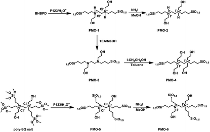
conc. HCl mixture at 60 °C for 6 h. The powder material was collected by filtration, washed with ethanol, and dried at ambient conditions. A similar preparation, but without BHBPD, was carried out for SBA-15 silica, herein referred to as SBA-15*. To make sure all P123 has been removed, 1 g of the solid ethanol-extracted material was subjected to additional Soxhlet extraction with 100 mL of methanol at 70 °C for 16 h. The obtained solid was dried overnight in ambient condition, then at 60 °C under vacuum for 4 h.An off-white powder material, hereafter referred to as OMO-1, was obtained from the co-condensation of TEOS and BHBPD. Because of the acidic conditions, OMO-1 was actually in the form of a quaternary ammonium chloride salt. OMO-1 was subjected to; (1) ion-exchange with ammonium iodide to obtain the corresponding ammonium iodide salt – OMO-2 and (2) dequaternization, regenerate the amine – OMO-3. To obtain a QAS with additional –OH groups, OMO-3 was quaternized with 2-iodoethanol to afford OMO-4. The structures of OMO-(1–4) are represented in Scheme 4.
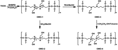 | ||
| Scheme 4 Synthesis of OMO-1 to OMO-4 via co-condensation followed by ion-exchange or quaternization. | ||
Ion-exchange was carried out as follows; 1 g of OMO-1 was dissolved in 30 mL of methanol followed by addition of 1 mL of ammonium iodide under a nitrogen atmosphere. The mixture was refluxed at 65 °C for 16 h. The resultant solid was recovered by filtration, washed with methanol, then Et2O and dried under vacuum at 70 °C for 4 h to afford a yellow powder (OMO-2). To regenerate the amine from OMO-1, 1 g of material was dispersed in 50 mL of ethanol, followed by the addition of 1 mL of triethylamine. After reflux at 60 °C for 2 h, the solid was recovered by hot-filtration and washed with boiling ethanol, then dried at 60 °C under vacuum for 4 h to afford an off-white powder material – OMO-3. OMO-3 was quaternized as described in method A to afford a yellow powder – OMO-4.
The preparation of OMOs from BHBPD-derived salt involves two steps; the synthesis of the salt, hereafter referred to as poly-SQ salt, followed by its co-condensation with TEOS. The poly-SQ salt was synthesized as follows; to a 25 mL two-neck round bottom flask containing 10 mL of toluene, 2 mL (2.83 mmol) of BHBPD was added. Under a nitrogen atmosphere, 2.0 equivalent of 3-chloropropyltrimethoxysilane was added. The reaction flask was sealed under nitrogen and refluxed at 85 °C for 24 h. Toluene and unreacted reagents were removed under reduced pressure at 90 °C to afford a brownish-yellow liquid. The procedure for the co-condensation of the poly-SQ salt and TEOS was similar to that of BHBPD and TEOS (OMO-1). An amount of poly-SQ salt was added to a pre-hydrolyzed TEOS solution with a nominal amine loading of 2.0 mmol per gram of silica. The template was extracted as described for OMO-1 to afford a light grey solid denoted OMO-5. Ion-exchange of OMO-5 with ammonium iodide (as described for OMO-1) produced a yellow solid, OMO-6 (Scheme 5).
Characterization of materials
The organic or nitrogen content (N-content) of all organosilicas was determined using thermogravimetric analysis (TGA) on a TA Q500 instrument. Sample were heated to 120 °C at 10 °C min−1 under flowing nitrogen and held for 30 min, to ensure the removal of physisorbed species (e.g. water and solvents). Then the temperature was raised to 800 °C under flowing nitrogen, then air at 800 °C for 10 min. The organic content was calculated based on the weight loss beyond 200 °C.
For solution NMR measurements, 13C and 1H NMR spectra were obtained using a Bruker AV 400 MHz spectrometer. Chemical shifts are reported in ppm relative to deuterated chloroform.
Where separation was needed to isolate the cyclic carbonate prior to NMR analysis, silica gel flash chromatography was used with a 3![[thin space (1/6-em)]](https://www.rsc.org/images/entities/char_2009.gif) :
:![[thin space (1/6-em)]](https://www.rsc.org/images/entities/char_2009.gif) 1 ethylacetate
1 ethylacetate![[thin space (1/6-em)]](https://www.rsc.org/images/entities/char_2009.gif) :
:![[thin space (1/6-em)]](https://www.rsc.org/images/entities/char_2009.gif) ether mixture as solvent.
ether mixture as solvent.
The reaction conditions were chosen such that the reaction was significantly away from total conversion; enabling a meaningful comparison of catalytic activity and stability. In a typical procedure, a 100 mL high pressure autoclave equipped with a magnetic stirrer was charged with 2 mL (17 mmol) of styrene epoxide (SO) and 2 mol% of organocatalyst (DMO, OMO or PMO). The reactor was directly pressurized with CO2 to 0.5 MPa and heated to 50 °C under stirring for 5 h. At the end of the reaction, the reactor was cooled with an ice bath to ≤15 °C and CO2 was released slowly. Then, 50 μL of dodecane (internal standard for GC analysis) was added to the reaction mixture, which was then suspended in diethyl ether and filtered off to recover the catalyst. After removal of all volatiles using a rotavap, a solvent-free reaction mixture was obtained. The spent catalyst was further stirred in acetone for 30 min, filtered off and dried in a vacuum oven at 70 °C for 2 h. TG analysis and nitrogen adsorption–desorption measurements were carried out on all spent catalysts to determine variations in N-content and textural properties.
Analysis of reaction mixture: about 0.2 μL of the solvent-free reaction mixture was injected into a Varian CP-3800 GC equipped with Agilent J&W VF-1ms capillary column (15 m length, 0.25 mm inner diameter and 0.25 μm film thickness) and a flame ionization detector (FID); with helium as carrier gas. The temperature program used for analysis was as follows: initial oven temperature 80 °C (1.5 min); ramp at 30 °C min−1 and held at 250 °C (3 min); injector port temperature: 200 °C; detector temperature: 250 °C. For solid reaction mixtures, 0.1 g of the mixture was dissolved in 0.2 mL of toluene, and 0.2 μL of this solution was injected into the GC.
13C and 1H NMR spectra of liquid samples were obtained using a Bruker AV 400 MHz spectrometer with tetramethylsilane as the internal standard. Chemical shifts are reported in ppm relative to deuterated chloroform.
Results and discussion
Characterization of mesoporous organosilicas
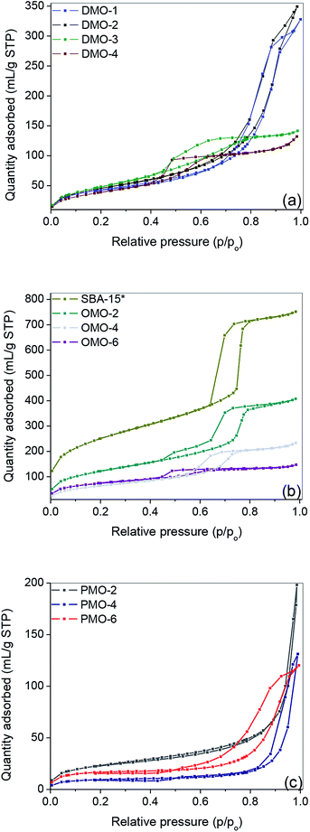
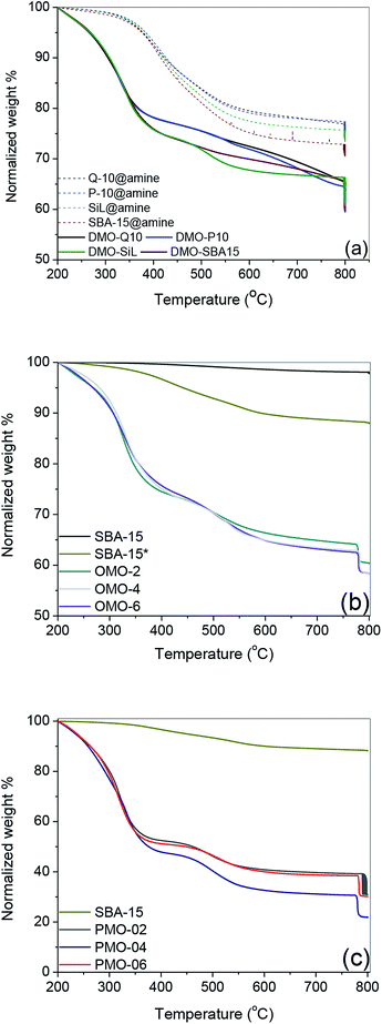
As shown in Fig. 1 and S1,† the nitrogen adsorption–desorption isotherms for the organosilica materials and SBA-15 were of Type IV with H1 hysteresis loop, characteristic of solids with mesopores. The corresponding textural properties and organic content are presented in Table 1. The TGA profiles of these materials may be found in Fig. 2. Compared to their pure silica, all organosilica materials derived by grafting, i.e. DMOs, had lower BET surface areas and pore volumes (Table 1, entries 1–8) – an indication of immobilization of organic species within the internal surface. The SBA-15 support obtained by template extraction in EtOH/HCl solution had a higher surface area and pore volume compared to that derived by calcination (Table 1, entry 7 vs. 9). Although thermal calcination in air can completely remove organic template, it may however cause significant framework shrinkage stemming from further silica condensation. On the other hand, template removal by solvent extraction minimizes framework shrinkage, leading to higher surface area, pore volume and number of silanols compared to its calcined counterpart.40,41| Entry | Material | Specific S.A. (m2 g−1) | Vp (mL g−1) | Dp (nm) | N-content (mmol g−1) |
|---|---|---|---|---|---|
| 1 | Q-10 | 316 | 1.34 | 18.2 | — |
| 2 | DMO-Q10 | 160 | 0.48 | 11.9 | 1.26 |
| 3 | P-10 | 327 | 1.53 | 21.2 | — |
| 4 | DMO-P10 | 170 | 0.54 | 12.0 | 1.22 |
| 5 | SiL | 478 | 0.83 | 9.2 | — |
| 6 | DMO-SiL | 182 | 0.22 | 4.6 | 1.37 |
| 7 | SBA-15 | 763 | 1.07 | 7.2 | — |
| 8 | DMO-SBA15 | 146 | 0.21 | 5.1 | 1.41 |
| 9 | SBA-15* | 913 | 1.23 | 6.18 | — |
| 10 | OMO-2 | 449 | 0.66 | 6.0 | 1.22 |
| 11 | OMO-4 | 241 | 0.37 | 5.8 | 1.29 |
| 12 | OMO-6 | 270 | 0.22 | 4.1 | 1.22 |
| 13 | PMO-2 | 86 | 0.31 | 15.7 | 2.38 |
| 14 | PMO-4 | 34 | 0.20 | 30 | 2.37 |
| 15 | PMO-6 | 60 | 0.18 | 16.7 | 2.11 |
The capillary condensation of all DMOs and OMOs were observed to be less sharp compared to their corresponding supports and SBA-15*, respectively; an indication of decreased pore size. This provided further evidence that immobilization of the organic moieties took place on the internal surface of the supports. Compared to DMOs and OMOs, all PMOs had significantly lower surface areas, while their pore volumes were also lower than the corresponding OMOs (Table 1, entries 10 vs. 13, 11 vs. 14 and 12 vs. 15).
Moreover, PMOs showed a broad pore size distribution (Fig. S2†). This finding may be attributed to the higher organic content of PMOs, which adversely affects their textural properties.
Similar organic contents were measured for all amine functionalized supports and DMOs (Fig. 2a). The calculated organic content of Q-10@amine, P-10@amine, SiL@amine and SBA-15@amine were 1.59, 1.70, 1.64 and 1.80 mmol g−1 respectively – accounting for a grafting efficiency between 80 and 90%. This finding illustrates that despite the smaller surface areas of P-10 and Q-10 silicas compared to SiL and SBA-15, their larger pore volume and pore diameter enabled them to accommodate as much BHBPDs as SiL and SBA-15.
The N-content per gram of silica support for both S@amine solids and DMOs being the same, the yield of the quaternization reactions was evaluated to be between 92 and 97%. This finding confirms the structure of DMOs, i.e. as immobilized symmetrical diammonium salts. The weight lost below 200 °C of SBA-15 was <2% compared to ca. 10% for SBA-15* (Fig. 2b), suggesting the presence of some P123 surfactant (vide infra). It is known that template removal via solvent extraction does not completely remove the surfactant.42 Hence, the N-content of all OMOs and PMOs were obtained taking into account the presence of about 8 wt% of surfactant. Relatively higher organic content, up to 80 wt%, was obtained for PMOs compared to DMOs and OMOs (Fig. 2c).
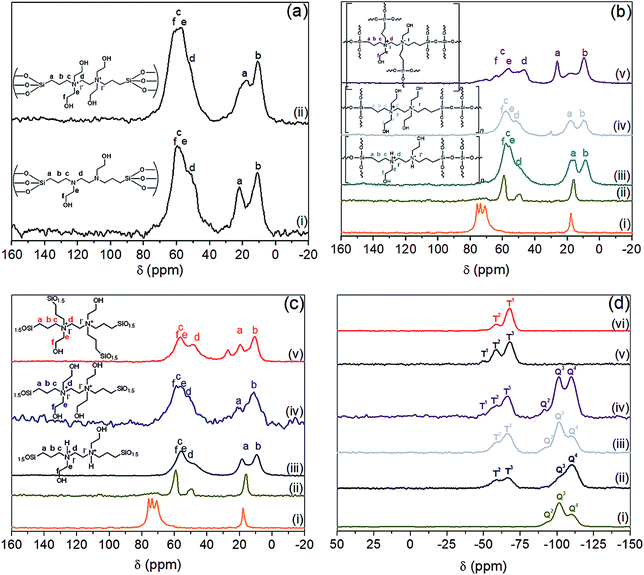
The 13C NMR of amine@Q-10 and DMO-Q10 showed peaks around 10, 17, 51, 56, 58 and 62 ppm, which were assigned to the five carbon nuclei of BHBPD as illustrated in Fig. 3a. As-synthesized SBA-15 exhibited resonances attributed to –CH2–CH– (76 and 74 ppm) and –CH3 (18 ppm) groups of the PPO, and –CH2– (71 ppm) of the PEO block of P123.43 Following template removal by solvent extraction, 13C NMR of the resultant material, SBA-15*, showed very low intensity signals between 71 and 75 ppm, and the complete disappearance of the signal at 18 ppm. Moreover, signals at 16, 50 and 59 ppm were assigned to trapped methanol and ethanol molecules used during template removal. Hence, the 8 wt% organic content of SBA-15*, as determined by TGA was assigned to the presence of small amount of template. As with DMOs, five carbon nuclei could be identified in the 13C NMR of all OMOs (Fig. 3b) and PMOs (Fig. 3c).
The 29Si CP MAS NMR spectra showed only Qn species for SBA-15*, Qn and Tn for DMOs and PMOs, and only Tn for PMOs (Fig. 3d). The characteristic resonances in the range of −89 to −118 ppm were ascribed to Qn units, with the peaks at about −97, −102.1 and −110.9 ppm corresponding to Q2 [Si(HO)2(OSi)2], Q3 [Si(HO)(OSi)3] and Q4 [Si(OSi)4] species, respectively (Fig. 3d(i)). All DMOs, OMOs and PMOs showed two intense signals at ca. −58 and −66 ppm, attributed to Si-species covalently bonded to carbon atoms, namely T2 [C–Si(OH)(OSi)2] and T3 [C–Si(OSi)3] respectively (Fig. 3d(i)–(iv)).44 These signals arise from immobilization of BHBPD onto the silica surface and framework of silica for DMOs and OMOs/PMOs, respectively. Furthermore, for some OMOs and PMOs, a weak shoulder at ca. 50 ppm, attributed to T1 [C–Si(OH)2(OSi)] species was also observed. The presence of T1 and T2-signals is an indication that the condensation process was not complete for these materials. Hence, the calculated nitrogen content based on TGA results, which assumes 100% condensation, may be slightly overestimated.
All materials showed IR absorption bands (Fig. 4 and S4†) at approximately 640, 800 and 1080 cm−1, which was attributed to Si–O–Si bonds of the silicate network. The broad band centered at ca. 3320 or 3440 cm−1 were assigned to the O–H stretching vibrations of silanol groups, hydroxyl groups of BHBPD and/or adsorbed water. A band at 1650 cm−1 confirmed the presence of adsorbed water, whose physisorption was enhanced by the ionic nature of the –N–I bond. Furthermore, the spectra of all organosilica materials showed –CH2– stretching vibrations of the propyl chain characterized by weak absorbance at ca. 3030 and 2980 cm−1, –CH2– bending at 1550 cm−1 and C–N stretching at 1450 cm−1.45 These findings are consistent with the presence of BHBPD on the silica supports. The absence of a band at 960 cm−1 suggests that the amount of uncondensed Si–OH groups was minimal; which is in agreement with 29Si MAS NMR data. It is worth noting that bands at slightly different wavenumbers were observed for PMOs and OMOs/DMOs, suggesting differences in the chemical environment between these two groups of materials.
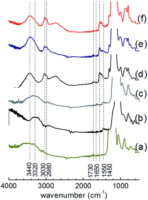 | ||
| Fig. 4 IR adsorption spectra of (a) SBA-15, (b) DMO-1, (c) OMO-4, (d) PMO-2, (e) PMO-4 and (f) PMO-6. | ||
Catalytic activity
The catalytic activity of iodide-containing organosilicas was evaluated using the cycloaddition of CO2 and styrene oxide (SO) to styrene carbonate (SC) under neat conditions. Because of its low activity, SO provides a more meaningful comparison than a highly active epoxide such as 1,2-epoxybutane (1,2-EB). The effect of temperature, time and CO2 pressure on the selectivity and yield is presented in Table 2, entries 1–11. At 100 °C, 4 h and 1 MPa CO2, yields and selectivity ≥ 97% were obtained (Table 2, entry 1) with DMO-SiL as catalysts. In an earlier study, we reported similar findings in the presence of N,N,N-tributyl-N-propylammonium iodide-functionalized mesoporous silicas.10 These results are in agreement with other reports where immobilized ammonium46 and phosphonium17 salts were used. To obtain yields significantly below 100%, the following conditions were; 50 °C, 5 h and 0.5 MPa CO2. As seen in Table 2, entries 2–11, conversion was found to be <50% for all catalysts. Amongst the DMOs, the highest yield was obtained with DMO-P10 and DMO-SiL (Table 2, entries 3 and 4). This may be attributed to smaller particle size of the silicas supports P-10 (40 μm) and SiL (40–60 μm) compared to Q-10 (75–150 μm) and SBA-15 (<150 μm).47| Entry | Catalyst | Reaction condition | Reaction quantification | Spent cat. | |||||
|---|---|---|---|---|---|---|---|---|---|
| Type | N-content (mmol g−1) | T (°C) | t (h) | PCO2 (MPa) | Yield (%) | Sel. (%) | Yield/g cat. (%/g) | Retained N-content (%) | |
| a Reaction conditions; 2 mol% catalysts based on N-content, 17 mmol styrene oxide (SO). | |||||||||
| 1 | DMO-SIL | 1.41 | 100 | 4 | 1.0 | 96.8 | 98.5 | 401.7 | 96.4 |
| 2 | DMO-Q10 | 1.22 | 50 | 5 | 0.5 | 26.2 | 94.0 | 94.0 | 96.5 |
| 3 | DMO-P10 | 1.26 | 50 | 5 | 0.5 | 31.8 | 98.6 | 117.7 | 93.5 |
| 4 | DMO-SiL | 1.41 | 50 | 5 | 0.5 | 31.6 | 98.5 | 131.1 | 96.8 |
| 5 | DMO-SBA15 | 1.37 | 50 | 5 | 0.5 | 24.3 | 98.0 | 98.1 | 94.9 |
| 6 | OMO-2 | 1.24 | 50 | 5 | 0.5 | 44.9 | 96.1 | 154.9 | 95.2 |
| 7 | OMO-4 | 1.29 | 50 | 5 | 0.5 | 38.3 | 97.8 | 145.1 | 97.6 |
| 8 | OMO-6 | 1.22 | 50 | 5 | 0.5 | 25.8 | 97.0 | 92.5 | 95.7 |
| 9 | PMO-2 | 2.38 | 50 | 5 | 0.5 | 23.9 | 98.5 | 167.2 | 95.7 |
| 10 | PMO-4 | 2.37 | 50 | 5 | 0.5 | 21.2 | 98.9 | 148.3 | 97.1 |
| 11 | PMO-6 | 2.11 | 50 | 5 | 0.5 | 20.0 | 98.2 | 131.7 | 93.8 |
| 12 | OMO-2 | 1.24 | 50 | 15 | 0.5 | 76.9 | 98.5 | 291.6 | 96.1 |
With respect to OMOs, a 45% yield of SC was obtained with OMO-2 (Table 2, entry 6). However, OMO-4 consisting of four CO2-activating hydroxyl groups, exhibited lower activity (Table 2, entry 7), suggesting that increasing the number of hydroxyl groups from two to four was not beneficial to OMOs. A similar finding by Cheng et al.,48 was attributed to an enhancement in hydrogen bond formation between the halide and additional OH groups, leading to decreased nucleophilicity or epoxide ring-opening ability of the iodide ion. Alternatively, the observed decrease in activity could originate from increase diffusion-constraints with additional ethylhydroxyl groups, such that any benefit in CO2 activation due to extra hydroxyl groups was suppressed by slow reaction kinetics. This finding suggests that similar to homogeneous systems,49 there is an optimal number of hydroxyl groups required for efficient activation of epoxides. A combination of diffusion-constrain and a high ratio of hydroxyl groups to organics may be at the origin of the low yield obtained with OMO-6 (Table 2, entry 8). Interestingly, OMO-4 with four hydroxyl groups, showed superior catalytic activity to all DMOs. This finding was attributed to the larger surface area and moderate pore volume of the latter, leading to enhanced accessibility to active sites and improved mass transport. PMOs were found to be the least active compared to DMOs and OMOs, with PMO-2 the most active of all PMOs – 24% yield (Table 2, entry 9). The inferior catalytic performance of PMOs was attributed to their low surface area, pore volume and disordered pore structure. Accordingly, OMO-2, the most active catalyst, was used to optimize the reaction conditions and material reusability.
Optimization of reaction time
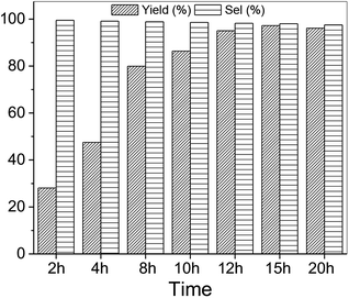
Using SO as substrate, an increase in yield (44.9 to 76.9%) was observed when the reaction time was raised from 5 to 15 h (Table 2, entry 6 vs. 12). Compared to 1,2-EB for instance, SO is significantly more difficult to activate, and expected to take significantly longer reaction times under mild conditions to attain high yields. However, prolonged reaction times may lead to the formation of side products, ultimately reducing product yield and selectivity. Hence, optimization of reaction time was carried out with 1,2-EB. As seen in Fig. 5, the yield of 1,2-butylene carbonate (1,2-BC) was found to peak after 15 h (97.2%), which is 25% more than was obtained for SC under similar conditions (Table 2, entry 12). Moreover, no noticeable change in selectivity (≥97.5%) was observed after 20 h. Nonetheless, a slight decrease in yield was recorded after 20 h, suggesting the onset of the formation of side products beyond 15 h. Hence, optimum reaction conditions for the synthesis of 1,2-BC using OMO-2 were; 2 mol% catalyst, 0.5 MPa CO2, 50 °C and 15 h.Reusability studies
One of the most attractive attributes of heterogeneous catalysts is their reusability. In this regard, OMO-2 was subjected to recycling experiments with 1,2-EB as substrate. As shown in Table 3, no significant changes in product yield and selectivity were observed over five cycles. Although a 7% decrease in organic content was observed compared to the fresh catalyst (Table 3, entry 1 vs. 2), the N-content of all spent catalyst was relatively constant, indicating the stable nature of OMO-2. This finding is consistent with the textural properties of fresh and spent catalysts being comparable.| Entry | Reaction | N-content (mmol g−1) | Yield (%) | Sel. (%) | BET SAa (m2 g−1) | Vpb (mL g−1) | Dpc (nm) |
|---|---|---|---|---|---|---|---|
| a BET surface area.b Pore volume.c Pore diameter.d Fresh catalyst.e First reuse. | |||||||
| 1 | Run 1d | 1.22 | 96.4 | 98.2 | 449 | 0.66 | 6.0 |
| 2 | Run 2e | 1.14 | 94.7 | 98.4 | 469 | 0.72 | 5.9 |
| 3 | Run 3 | 1.11 | 95.1 | 98.5 | 453 | 0.68 | 5.9 |
| 4 | Run 4 | 1.13 | 93.2 | 97.8 | 446 | 0.69 | 6.0 |
| 5 | Run 5 | 1.12 | 94.3 | 98.0 | 456 | 0.61 | 6.2 |
Scope of substrates
The scope of OMO-2 was investigated using four additional substrates, namely propylene oxide (PO), epichlorohydrin (ECH), cyclohexene oxide (CHO) and 3-glycidyloxypropyltrimethoxysilane (GPS) to synthesize propylene carbonate (PC), 4-(chloromethyl)-1,3-dioxolan-2-one (4-CDO) and hexahydrobenzo[d][1,3]dioxol-2-one (HDO) and 4-((3-(trimethoxysilyl)propoxy)methyl)-1,3-dioxolan-2-one (4-PDO), respectively. An excellent yield (98.2%) of PC was obtained after 10 h under mild reaction conditions (Table 4, entry 1). Doubling the reaction temperature and pressure led to a very good yield (96%) after just 3 h (Table 4, entry 2). The observed marginal decreases in yield and selectively were attributed to the formation of side products, which are facilitated at higher temperatures.Similar high yields were obtained in the synthesis of 1,2-BC and 4-(chloromethyl)-1,3-dioxolan-2-one under mild reaction conditions (Table 4, entries 3 and 5). As with the synthesis of PC, similar high yields of 1,2-BC and 4-CDO were obtained at 4 h, but at higher temperature and pressure (Table 4, entries 4 and 6). It is worth noting the high yield and selectively of these cyclic carbonates under the current mild reactions condition using a metal-free catalyst. Compared to other organocatalaysts immobilized on inert support, namely; ammonium salts on nanocrystalline zeolites,50 imidazole-based ionic liquid (IL) on graphene oxide51 and covalent organic frameworks,52 triphosphonate cavitand on SBA-15,53 phosphonium-based polymeric IL,54 phosphonium salt on polystyrene,55 OMO-2 was significantly more active.
As noted earlier, under the current mild reaction conditions, the yield of SC was limited to 77% (Table 4, entry 7). However, 97% yield was obtained by doubling the reaction temperature and pressure, while limiting the reaction to 4 h (Table 4, entry 8). Furthermore, reacting CHO and GPS under the current mild reaction conditions led to very low yields (Table 4, entries 9 and 11). Nonetheless, significantly higher yields were obtained at higher temperature and pressure (Table 4, entries 10 and 12). This is not surprising as these three epoxides are much more difficult to activate (due to steric hindrance) than the first three in Table 4.
Conclusions
A series of novel DMOs, OMOs and PMOs were prepared, characterized and screened against the cycloaddition reaction of CO2 and epoxides. Results showed that OMOs were the most active class of all materials. Furthermore, OMO-2, containing two hydroxyl groups per immobilized molecule was found to be the most active material. For substrates which are easy to activate such as PO, 1,2-EB and ECH, excellent yield and selectivity were obtained under mild reaction conditions (0.5 MPa CO2, 50 °C and 10–15 h). However, higher CO2 pressure and temperature were required with substrates which are more difficult to activate, e.g. SO, CHO and GPS. Furthermore, OMO-2 proved to be both chemically and structurally stable after five cycles of 1,2-EB synthesis.Conflicts of interest
There are no conflicts to declare.Acknowledgements
Financial support from the Natural Sciences and Engineering Research Council of Canada (NSERC) is gratefully acknowledged.References
- H. Ritchie and M. Roser, Our World Data, 2017 Search PubMed.
- IPCC, Intergov. Panel Clim. Chang., 2018, pp. 1–32 Search PubMed.
- E. I. Koytsoumpa, C. Bergins and E. Kakaras, J. Supercrit. Fluids, 2018, 132, 3–16 CrossRef CAS.
- J. Luis Míguez, J. Porteiro, R. Pérez-Orozco, D. Patiño and S. Rodríguez, Appl. Energy, 2018, 211, 1282–1296 CrossRef.
- C. Song, Q. Liu, N. Ji, S. Deng, J. Zhao, Y. Li, Y. Song and H. Li, Renewable Sustainable Energy Rev., 2018, 82(Part 1), 215–231 CrossRef CAS.
- M. Aresta, A. Dibenedetto and E. Quaranta, J. Catal., 2016, 343, 2–45 CrossRef CAS.
- M. Cokoja, M. E. Wilhelm, M. H. Anthofer, W. A. Herrmann and F. E. Kühn, ChemSusChem, 2015, 8, 2436–2454 CrossRef CAS PubMed.
- J. W. Comerford, I. D. V. Ingram, M. North and X. Wu, Green Chem., 2015, 17, 1966–1987 RSC.
- M. North, in New and Future Developments in Catalysis - Activation of Carbon Dioxide, Elsevier B.V., 2013, pp. 379–413 Search PubMed.
- J. M. Kolle and A. Sayari, J. CO2 Util., 2018, 26, 564–574 CrossRef CAS.
- H. Büttner, K. Lau, A. Spannenberg and T. Werner, ChemCatChem, 2015, 7, 459–467 CrossRef.
- H. Büttner, J. Steinbauer and T. Werner, ChemSusChem, 2015, 8, 2655–2669 CrossRef PubMed.
- L. Wang, L. Lin, G. Zhang, K. Kodama, M. Yasutake and T. Hirose, ChemComm., 2014, 50, 14813–14816 RSC.
- X. F. Liu, Q. W. Song, S. Zhang and L. N. He, Catal. Today, 2016, 263, 69–74 CrossRef CAS.
- A. Siewniak, K. Jasiak and S. Baj, Appl. Catal. Gen., 2014, 482, 266–274 CrossRef CAS.
- Y. Kumatabara, M. Okada and S. Shirakawa, ACS Sustain. Chem. Eng., 2017, 5, 7295–7301 CrossRef CAS.
- J. Steinbauer, L. Longwitz, M. Frank, J. Epping, U. Kragl and T. Werner, Green Chem., 2017, 19, 4435–4445 RSC.
- M. North, R. Pasquale and C. Young, Green Chem., 2010, 12, 1514 RSC.
- G. Fiorani, W. Guo and A. W. Kleij, Green Chem., 2015, 17(3), 1375–1389 RSC.
- F. D. Bobbink and P. J. Dyson, J. Catal., 2016, 343, 52–61 CrossRef CAS.
- J. K. Lee, Y. J. Kim, Y. S. Choi, H. Lee, J. S. Lee, J. Hong, E. K. Jeong, H. S. Kim and M. Cheong, Appl. Catal. B Environ., 2012, 111–112, 621–627 CrossRef CAS.
- C. Martín, G. Fiorani and A. W. Kleij, ACS Catal., 2015, 5, 1353–1370 CrossRef.
- Y. Ren, O. Jiang, H. Zeng, Q. Mao and H. Jiang, RSC Adv., 2016, 6, 3243–3249 RSC.
- A. J. Kamphuis, F. Picchioni and P. P. Pescarmona, Green Chem., 2019, 21, 406–448 RSC.
- T. Sakai, Y. Tsutsumi and T. Ema, Green Chem., 2008, 10, 337 RSC.
- F. Adam, J. N. Appaturi and E. P. Ng, J. Mol. Catal. A Chem., 2014, 386, 42–48 CrossRef CAS.
- B. Chatelet, L. Joucla, J.-P. Dutasta, A. Martinez and V. Dufaud, J. Mater. Chem. A, 2014, 2, 14164 RSC.
- X. D. Lang and L. N. He, Chem. Rec., 2016, 1337–1352 CrossRef CAS PubMed.
- S. Udayakumar, V. Raman, H. L. Shim and D. W. Park, Appl. Catal. Gen., 2009, 368, 97–104 CrossRef CAS.
- S. Udayakumar, S. W. Park, D. W. Park and B. S. Choi, Catal. Commun., 2008, 9, 1563–1570 CrossRef CAS.
- E. A. Prasetyanto, M. B. Ansari, B. H. Min and S. E. Park, Catal. Today, 2010, 158, 252–257 CrossRef CAS.
- M. Liu, X. Lu, L. Shi, F. Wang and J. Sun, ChemSusChem, 2017, 10, 1110–1119 CrossRef CAS PubMed.
- J. Peng, S. Wang, H. J. Yang, B. Ban, Z. Wei, L. Wang and B. Lei, Fuel, 2018, 224, 481–488 CrossRef CAS.
- X. Zhang, W. Geng, C. Yue, W. Wu and L. Xiao, J. Environ. Chem. Eng., 2016, 4, 2565–2572 CrossRef CAS.
- J. Zhu, K. Kailasam, X. Xie, R. Schomaecker and A. Thomas, Chem. Mater., 2011, 23, 2062–2067 CrossRef CAS.
- R. Serna-guerrero, E. Da and A. Sayari, Ind. Eng. Chem. Res., 2008, 47, 9406–9412 CrossRef CAS.
- B. Lindlar, M. Lüchinger, A. Röthlisberger, M. Haouas, G. Pirngruber, A. Kogelbauer and R. Prins, J. Mater. Chem., 2002, 12, 528–533 RSC.
- X. Feng, G. E. Fryxell, L. Q. Wang, A. Y. Kim, J. Liu and K. M. Kemner, Science, 1997, 276, 923–926 CrossRef CAS.
- E. Da'na and A. Sayari, Chem. Eng. J., 2011, 166, 445–453 CrossRef.
- M. Barczak, New J. Chem., 2018, 42, 4182–4191 RSC.
- C. Knöfel, M. Lutecki, C. Martin, M. Mertens, V. Hornebecq and P. L. Llewellyn, Microporous Mesoporous Mater., 2010, 128, 26–33 CrossRef.
- R. E. Mishler, A. V. Biradar, C. T. Duncan, E. A. Schiff and T. Asefa, Chem. Commun., 2009, 6201–6203 RSC.
- H. H. Oc and K. B. Yoon, Bull. Korean Chem. Soc., 2008, 29, 911–912 CrossRef.
- C. Li, J. Yang, X. Shi, J. Liu and Q. Yang, Microporous Mesoporous Mater., 2007, 98, 220–226 CrossRef CAS.
- C. S. Srikanth and S. S. C. Chuang, ChemSusChem, 2012, 5, 1435–1442 CrossRef CAS PubMed.
- C. Kohrt and T. Werner, ChemSusChem, 2015, 8, 2031–2034 CrossRef CAS PubMed.
- M. North and P. Villuendas, ChemCatChem, 2012, 4, 789–794 CrossRef CAS.
- W. Cheng, B. Xiao, J. Sun, K. Dong, P. Zhang, S. Zhang and F. T. T. Ng, Tetrahedron Lett., 2015, 56, 1416–1419 CrossRef CAS.
- J. Sun, L. Han, W. Cheng, J. Wang, X. Zhang and S. Zhang, ChemSusChem, 2011, 4, 502–507 CrossRef CAS PubMed.
- B. Sarmah and R. Srivastava, Ind. Eng. Chem. Res., 2017, 56, 8202–8215 CrossRef CAS.
- J. Zhu, S. Wang, Y. Gu, B. Xue and Y. Li, Mater. Chem. Phys., 2018, 208, 68–76 CrossRef CAS.
- J. Qiu, Y. Zhao, Z. Li, H. Wang, Y. Shi and J. J. Wang, ChemSusChem, 2019, 12(11), 2421–2427 CAS.
- A. Mirabaud, A. Martinez, F. Bayard, J. P. Dutasta and V. Dufaud, New J. Chem., 2018, 42, 16863–16874 RSC.
- Y. Liu, W. Cheng, Y. Zhang, J. Sun and S. Zhang, Green Chem., 2017, 19, 2184–2193 RSC.
- X. Yan, R. Fu, F. Liu, Y. Pan, X. Ding and G. He, Ind. Eng. Chem. Res., 2018, 57, 3195–3203 CrossRef CAS.
Footnote |
| † Electronic supplementary information (ESI) available. See DOI: 10.1039/c9ra05466a |
| This journal is © The Royal Society of Chemistry 2019 |


