A novel synthesis towards a vanadium pentoxide porous nanodisk film as a cathode material for advanced Li-ion hybrid capacitors†
Xiaolin
Liu
a,
Yuqi
Jiang
a,
Deliang
Ba
b,
Wan
Zhou
a,
Yuanyuan
Li
*b and
Jinping
Liu
 *ac
*ac
aSchool of Chemistry, Chemical Engineering and Life Science, and State Key Laboratory of Advanced Technology for Materials Synthesis and Processing, Wuhan University of Technology, Wuhan, 430070, Hubei, China. E-mail: liujp@whut.edu.cn
bSchool of Optical and Electronic Information, Huazhong University of Science and Technology, Wuhan, 430074, Hubei, China. E-mail: liyynano@hust.edu.cn
cState Center for International Cooperation on Designer Low-carbon & Environmental Materials, School of Materials Science and Engineering, Zhengzhou University, Zhengzhou 450001, Henan, China
First published on 25th November 2019
Abstract
A V2O5 porous nanodisk thin film is synthesized through a simple hydrothermal and subsequent VO2 template oxidation strategy. For the first time, V2O5 is employed as a cathode rather than an anode to construct lithium-ion hybrid capacitors. This design effectively utilizes the intrinsic layered structure of V2O5 for facile Li+ intercalation and facilitates the charge balance with the capacitive electrode, enabling superior performance of the device.
With the increasing market demand of new energy vehicles and flexible electronics, the development of energy storage devices with high power and energy densities is particularly urgent.1 Among various energy storage systems, lithium-ion batteries (LIBs) can provide high energy density due to faradaic electrode reactions, but have limited power density.2–4 Compared with LIBs, supercapacitors show high power density and outstanding cycling stability due to the surface/near-surface charge storage behavior; however, they generally deliver low energy density.4–6 To achieve high comprehensive performance, lithium-ion hybrid capacitors (LIHCs) combining the advantages of LIBs and supercapacitors were developed, which are assembled with one battery-type electrode and one capacitive electrode.7–9 However, there remains a great challenge in realizing the kinetics balance and charge balance between the two electrodes of different energy storage mechanisms.1,2 It is of utmost importance to develop a high-rate battery electrode with comparable capacity to match with the capacitive electrode in LIHCs.
Vanadium oxides possess rich varieties of structural motifs due to their different atomic configurations and multiple V valence states,10–13 which provides superior Li ion storage capability.14,15 In particular, vanadium pentoxide (V2O5) exhibits a layered structure and large interlayer spacing (4.37 Å) that benefit the accommodation of Li+.16 In previous studies, V2O5 was often employed as an anode to construct LIHCs. Unfortunately, when V2O5 is used as an anode, the crystal structure will be completely damaged during cycling due to the conversion reaction mechanism, resulting in poor cycling stability. In such a case, the benefits of the intrinsic layered structure cannot be utilized, which also leads to poor rate performance. In addition, like anodes of other transition metal oxides, the capacity (500–1000 mA h g−1) of the V2O5 anode is much higher than that of the capacitive cathode,17,18 which causes great difficulty in realizing the charge balance between the anode and cathode in LIHCs. Then, it is of great interest to design LIHCs with V2O5 as a cathode. In order to achieve high performance of the above proposed LIHC, it is still necessary to boost the rate performance of the V2O5 cathode. Therefore, designing a binder-free film electrode with a porous nanostructure may be one of the best choices, as such an electrode architecture can provide not only direct electron transport channels, but also shortened ion diffusion paths benefiting from the sufficient electrode/electrolyte contact interface.19,20
Herein, we report a unique VO2 template oxidation strategy to synthesize a V2O5 porous nanodisk film and further use it as a cathode to design a LIHC. The removal of residual organic species from the VO2 structure via direct high temperature annealing in air gives rise to the formation of abundant pores in V2O5 nanodisks. The porous structure combined with the merits of a binder-free architecture enables good rate capability of the electrode. By pairing with a prelithiated activated carbon (LiAC) anode, the assembled thin-film LIHC device (the energy storage mechanism is elucidated in Fig. S1, ESI†) also delivers remarkable energy densities (146 W h kg−1, 13 mW h cm−3) and high power densities. Furthermore, the device still works well when bended or even folded.
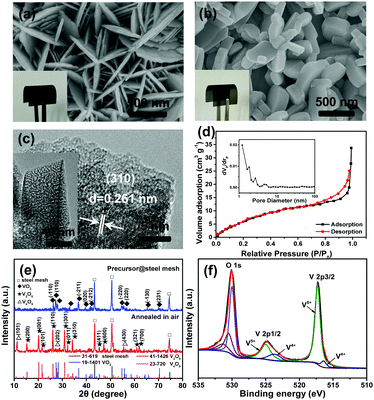
The precursor VO2 nanosheet array was grown on a thin steel mesh current collector by a simple hydrothermal method, and the V2O5 nanodisk film was obtained via further oxidization of VO2 in air at 550 °C (see the ESI† for details). Scanning electron microscopy (SEM) images show that the nanostructures are uniformly grown on the surface of each stem of the steel meshes (Fig. S2, ESI†). Compared to the precursor VO2, the V2O5 film exhibits a different color with a clear structural transformation from thin nanosheets to thick nanodisks (Fig. 1a and b and insets). In addition, a highly porous structure of V2O5 can be detected by transmission electron microscopy (TEM), as shown in Fig. 1c. The lattice fringes with a spacing of ∼0.261 nm correspond well to the (310) crystal planes of V2O5. The N2 adsorption–desorption isotherm in Fig. 1d displays the type-IV hysteresis loop, further indicating the existence of porous features. The pores are distributed with the sizes smaller than 5 nm, including both the mesopores and micropores (inset in Fig. 1d). To understand the formation mechanism of the pores, thermal gravimetric analysis (TGA) was performed (Fig. S3a, ESI†). In addition to the weight loss of ∼2.12 wt% below 250 °C that is attributed to the loss of surface-adsorbed and weakly bound water, a weight drop of ∼4.63% at around 270 and 350 °C with two noticeable exothermic peaks is observed, which is consistent with the TGA feature of oxalic acid.21 Therefore, organic species of oxalic acid was present in VO2 sheets during the hydrothermal process, the removal of which is responsible for the porous structure within the V2O5 disks.
The crystal structure and component of the V2O5 film electrode was further characterized by X-ray diffraction (XRD), X-ray photoelectron spectroscopy (XPS) and Raman spectroscopy. As shown in Fig. 1e, the XRD peaks clearly indicate the complete transformation from triclinic VO2 (JCPDS Card No. 19-1401) to orthorhombic V2O5 (JCPDS Card No. 41-1426) with a trace amount of V4O9 (not fully oxidized) after annealing the electrode in air. The skeleton bent vibration at 146 cm−1 and the stretching vibration of vanadyl at 997 cm−1 in the Raman spectrum are characteristic of the layered structure of V2O5 (Fig. S3b, ESI†).22,23 The full XPS spectrum (Fig. S3c, ESI†) demonstrates the presence of V and O elements. After deconvolution, the asymmetric shape of the V2p band can be separated into two sets of valence states.10 In detail, the spin-orbital splitting components of V2p3/2 and 2p1/2 peaks are observed at 517.2 and 524.7 eV, respectively (Fig. 1f).24,25 The V2p3/2 peak of vanadium can be divided into two peaks at binding energies of 517.3 and 516.2 eV, respectively, assigned to V5+ and V4+.26,27 The V2p1/2 peak can also be divided into two binding energies of 524.9 and 523.6 eV attributed to V5+ and V4+, respectively.28 Nevertheless, the oxide with V5+ is found to be the dominant phase.
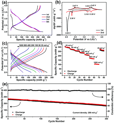
Next, the electrochemical performance of the V2O5 nanodisk film electrode was measured. The charge–discharge profiles of the V2O5 electrode within 2.0 to 4.0 V (vs. Li/Li+) at 100 mA g−1 are displayed in Fig. 2a. In the first discharge curve, there are obvious lithium insertion plateaus. Subsequently, the plateaus become invisible, indicating that the crystallinity decreases after the first lithiation/delithiation (Fig. S4, ESI†).28 The differential capacity versus potential plots in Fig. 2b show three pairs of reversible small redox peaks after the first cycle. The three cathodic peaks at 3.39, 3.18 and 2.30 V represent the multistep insertion process of lithium ions into V2O5, corresponding to the phase transition of α-V2O5 to ε-Li0.5V2O5, δ-LiV2O5, and γ-Li2V2O5, respectively.29 In reverse, the anodic peaks observed at 2.47, 3.32 and 3.43 V can be ascribed to the de-insertion of Li+ from V2O5.30Fig. 2c and d further show the rate capability. The V2O5 electrode exhibits similar charge/discharge profiles at various current densities with high coulombic efficiencies. At 25 mA g−1, the capacity is as high as ∼300 mA h g−1. With the current density increasing 64 times from 25 to 1600 mA g−1, a capacity of 104 mA h g−1 can still be maintained, indicative of excellent rate performance. Our V2O5 electrode also shows good cycling stability, as shown in Fig. 2e. After 300 times cycling at 200 mA g−1, the reversible capacity is still 162.9 mA h g−1, which maintains 68% of the initial capacity. The capacity loss rate is approximately 0.11% per cycle, which is superior to those of other nanostructured V2O5 electrodes, such as V2O5 nanofibers (0.52% per cycle)31 and carbon supported V2O5 nanotubes (0.42% per cycle).28
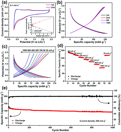
To further explore the electrochemical merits of our V2O5 nanodisk film, an LiAC(−)//V2O5(+) LIHC device using V2O5 as a cathode and LiAC as an anode was assembled and tested. The charge and discharge behavior of LiAC (KYP-50) was evaluated in a half cell prior to the construction of the LIHC. After prelithiation and formation of a stable solid electrolyte interface (Fig. S5a, ESI†),32 the LiAC electrode exhibits stable CVs and charge–discharge curves (Fig. 3a and b) in the potential range of 0.3–2.4 V (vs. Li/Li+). Fig. S5b (ESI†) shows the CVs of the LiAC at different sweep rates. The cathodic and anodic currents Ip are plotted with sweep rates (v) and shown in the inset of Fig. 3a. The results can be well fitted with a linear dependence of Ip with v at relatively low sweep rates, which indicates that the electrochemical process manifests a capacitive behavior6 (although this process is different from the case when AC is used as the cathode; Fig. S6, ESI†). Further charge/discharge testing at various current densities (Fig. 3c and d) reveals a good rate performance of the LiAC electrode. The reversible discharge capacity can reach 150 mA h g−1 at 25 mA g−1; at 1600 mA g−1, a capacity of 70 mA h g−1 can still be obtained. The LiAC electrode also displays good cycling stability at 200 mA g−1. As shown in Fig. 3e, ∼80% of the initial capacity can be retained after 1000 continuous cycles.
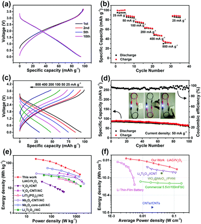
Fig. 4 illustrates the electrochemical performance of the assembled LIHC device within 0.01–3.7 V. Based on the half-cell results, the mass ratio of the anode to cathode is set as 2.3![[thin space (1/6-em)]](https://www.rsc.org/images/entities/char_2009.gif) :
:![[thin space (1/6-em)]](https://www.rsc.org/images/entities/char_2009.gif) 1 to realize the charge balance. As shown in Fig. 4a–c and Fig. S7 (ESI†), our device always exhibits almost linear charge–discharge plots at different current densities, indicative of a capacitive behavior. Good rate performance is also achieved, with ∼40% of the initial capacity retained when the current is increased 32 times to 800 mA g−1. The device can be subjected to continuous cycling with gradually increased current rates, and more importantly, when the current turns back to the initial value of 25 mA g−1, the capacity is almost recovered. Fig. 4d demonstrates the good cycling stability of the device. The charge/discharge capacity shows small loss after 100 cycles, with high coulombic efficiencies of 95–100%.
1 to realize the charge balance. As shown in Fig. 4a–c and Fig. S7 (ESI†), our device always exhibits almost linear charge–discharge plots at different current densities, indicative of a capacitive behavior. Good rate performance is also achieved, with ∼40% of the initial capacity retained when the current is increased 32 times to 800 mA g−1. The device can be subjected to continuous cycling with gradually increased current rates, and more importantly, when the current turns back to the initial value of 25 mA g−1, the capacity is almost recovered. Fig. 4d demonstrates the good cycling stability of the device. The charge/discharge capacity shows small loss after 100 cycles, with high coulombic efficiencies of 95–100%.
Our V2O5 film was grown tightly on a thin steel mesh without any binders or additives, which was not even able to peel off during repeated bending. This feature encourages us to assemble a soft-packing LIHC device to check the flexibility. The inset in Fig. 4d shows the optical images of our prototype device, which can efficiently power a 3.0 V white LED indicator under severe bending and folding conditions. The potential of our LIHC for energy storage application can be further manifested by its energy and power densities. Fig. 4e shows the Ragone plot of gravimetric energy density versus power density of our device, including data from previously reported systems for comparison. In general, the gravimetric energy densities of our LIHC (146 W h kg−1 at 24 W kg−1; 78 W h kg−1 at 252 W kg−1) are much larger than those of LIHCs using vanadium oxides as the anode, such as V2O5–CNT//AC (40 W h kg−1 at 200 W kg−1)33 and V2O5//CNT (18 W h kg−1 at 42 W kg−1).34 The energy densities are also superior to many other LIHCs such as Nb2O5–CNT//AC (40 W h kg−1 at 20 W kg−1),35 Nb2O5 core-cell//AC (63 W h kg−1 at 70 W kg−1),36 LiTi2(PO4)3//AC (24 W h kg−1 at 200 W kg−1)37 and Li4Ti5O12//AC (33 W h kg−1 at 50 W kg−1).38 At a high power density of 1396 W kg−1, the energy density of our device is still as high as 35 W h kg−1, better than conventional supercapacitors. Furthermore, our device delivers high volumetric energy densities of 13 mW h cm−3 at 3 mW cm−3 and 4.2 mW h cm−3 at 71.9 mW cm−3 (Fig. 4f), which are higher than the values of previous thin-film or flexible LIHCs, such as Li4Ti5O12//CNT (∼2.5 mW h cm−3 at 45 mW cm−3)39 and WO3−x@MoO3−x//PANI (∼1.9 mW h cm−3 at 40 mW cm−3).40 The values are even better than those of commercial Li thin-film batteries and supercapacitors.
In summary, a V2O5 porous nanodisk film is synthesized directly on a current collector by a simple hydrothermal and subsequent template oxidation method. The V2O5 electrode exhibits high capacity and good rate performance, which is attributed to the direct electron transport along the ordered electrode architecture and rapid Li-ion migration within the porous nanodisk structure. The resulting LIHC device delivers high energy and power densities as well as good flexibility. This work highlights the importance of using the intrinsic layered structure of materials for developing hybrid capacitors.
This work was supported by the National Natural Science Foundation of China (Grant No. 51872104, 51672205 and 51972257), the National Key R&D Program of China (Grant No. 2016YFA0202602), and the Natural Science Foundation of Hubei Province (2018CFB581).
Conflicts of interest
There are no conflicts to declare.References
- W. H. Zuo, R. Z. Li, C. Zhou, Y. Y. Li, J. L. Xia and J. P. Liu, Adv. Sci., 2017, 4, 1600539 CrossRef PubMed.
- H. Kim, M.-Y. Cho, M.-H. Kim, K.-Y. Park, H. Gwon, Y. Lee, K. C. Roh and K. Kang, Adv. Energy Mater., 2013, 3, 1500–1506 CrossRef CAS.
- X. Zhao, H. E. Wang, J. Cao, W. Cai and J. Sui, Chem. Commun., 2017, 53, 10723–10726 RSC.
- Q. Wang, Z. H. Wen and J. H. Li, Adv. Funct. Mater., 2006, 16, 2141–2146 CrossRef CAS.
- S. W. Lee, N. Yabuuchi, B. M. Gallant, S. Chen, B. S. Kim, P. T. Hammond and Y. Shao-Horn, Nat. Nanotechnol., 2010, 5, 531–537 CrossRef CAS PubMed.
- B. H. Deng, T. Y. Lei, W. H. Zhu, L. Xiao and J. P. Liu, Adv. Funct. Mater., 2018, 28, 1704330 CrossRef.
- Y. Q. Jiang and J. P. Liu, Energy Environ. Mater., 2019, 2, 30–37 CrossRef.
- G. Qu, B. B. Tian, C. L. Su, Y. W. Tang and Y. Li, Chem. Commun., 2018, 54, 10355–10358 RSC.
- Y. Xu, E. M. Lotfabad, H. Wang, B. Farbod, Z. Xu, A. Kohandehghan and D. Mitlin, Chem. Commun., 2013, 49, 8973–8975 RSC.
- H. E. Wang, X. Zhao, K. Yin, Y. Li, L. Chen, X. Yang, W. Zhang, B. L. Su and G. Cao, ACS Appl. Mater. Interfaces, 2017, 9, 43665–43673 CrossRef CAS PubMed.
- W. H. Zhu, R. Z. Li, P. Xu, Y. Y. Li and J. P. Liu, J. Mater. Chem. A, 2017, 5, 22216–22223 RSC.
- Y. Zhang, X. Jing, Q. Wang, J. Zheng, H. Jiang and C. Meng, Dalton Trans., 2017, 46, 15048–15058 RSC.
- X. Liu, J. Zeng, H. Yang, K. Zhou and D. Pan, RSC Adv., 2018, 8, 4014–4031 RSC.
- D. Graf, J. Schläfer, S. Garbe, A. Klein and S. Mathur, Chem. Mater., 2017, 29, 5877–5885 CrossRef CAS.
- C. Wu, F. Feng and Y. Xie, Chem. Soc. Rev., 2013, 42, 5157–5183 RSC.
- M. Liu, B. Su, Y. Tang, X. Jiang and A. Yu, Adv. Energy Mater., 2017, 7, 1700885 CrossRef.
- F. Cheng and J. Chen, J. Mater. Chem., 2011, 21, 9841–9848 RSC.
- Y. Zhao, X. Li, B. Yan, D. Xiong, D. Li, S. Lawes and X. Sun, Adv. Energy Mater., 2016, 6, 1502175 CrossRef.
- H. Gwon, J. Hong, H. Kim, D.-H. Seo, S. Jeon and K. Kang, Energy Environ. Sci., 2014, 7, 538–551 RSC.
- J. Jiang, Y. Li, J. P. Liu, X. Huang, C. Yuan and X. W. Lou, Adv. Mater., 2012, 24, 5166–5180 CrossRef CAS.
- M. R. Udupa, Thermochim. Acta, 1981, 51, 169–173 CrossRef CAS.
- Q. Su, X. Q. Liu, H. L. Ma, Y. P. Guo and Y. Y. Wang, J. Solid State Electrochem., 2008, 12, 919–923 CrossRef CAS.
- P. Chen, G. Zheng, G. Guo, Z. Wang, J. Tang, S. Li, Z. Wen, S. Ji and J. Sun, J. Alloys Compd., 2019, 784, 574–583 CrossRef CAS.
- Z. Li, G. Liu, M. Guo, L.-X. Ding, S. Wang and H. Wang, Electrochim. Acta, 2015, 173, 131–138 CrossRef CAS.
- X. Liang, G. Gao, Y. Liu, T. Zhang and G. Wu, J. Alloys Compd., 2017, 715, 374–383 CrossRef CAS.
- Q. Wei, Z. Jiang, S. Tan, Q. Li, L. Huang, M. Yan, L. Zhou, Q. An and L. Mai, ACS Appl. Mater. Interfaces, 2015, 7, 18211–18217 CrossRef CAS.
- F. Xiao, X. Song, Z. Li, H. Zhang, L. Zhang, G. Lei, Q. Xiao, Z. Hu and Y. Ding, J. Mater. Chem. A, 2017, 5, 17432–17441 RSC.
- X. Liang, G. Gao, S. Feng, Y. Du and G. Wu, J. Alloys Compd., 2019, 772, 429–437 CrossRef CAS.
- X. F. Zhang, K. X. Wang, X. Wei and J. S. Chen, Chem. Mater., 2011, 23, 5290–5292 CrossRef CAS.
- Y. Li, J. Yao, E. Uchaker, J. Yang, Y. Huang, M. Zhang and G. Cao, Adv. Energy Mater., 2013, 3, 1171–1175 CrossRef CAS.
- Y. L. Cheah, N. Gupta, S. S. Pramana, V. Aravindan, G. Wee and M. Srinivasan, J. Power Sources, 2011, 196, 6465–6472 CrossRef CAS.
- X.-F. Luo, C.-H. Yang, Y.-Y. Peng, N.-W. Pu, M.-D. Ger, C.-T. Hsieh and J.-K. Chang, J. Mater. Chem. A, 2015, 3, 10320–10326 RSC.
- Z. Chen, V. Augustyn, J. Wen, Y. Zhang, M. Shen, B. Dunn and Y. Lu, Adv. Mater., 2011, 23, 791–795 CrossRef CAS.
- V. Aravindan, Y. L. Cheah, W. F. Mak, G. Wee, B. V. R. Chowdari and S. Madhavi, ChemPlusChem, 2012, 77, 570–575 CrossRef CAS.
- X. Wang, G. Li, Z. Chen, V. Augustyn, X. Ma, G. Wang, B. Dunn and Y. Lu, Adv. Energy Mater., 2011, 1, 1089–1093 CrossRef CAS.
- E. Lim, C. Jo, H. Kim, M. Kim, Y. Mun, J. Chun, Y. Ye, J. Hwang, K. Ha and K. J. A. N. Roh, ACS Nano, 2015, 9, 7497–7505 CrossRef CAS.
- J.-Y. Luo and Y.-Y. Xia, J. Power Sources, 2009, 186, 224–227 CrossRef CAS.
- H.-G. Jung, N. Venugopal, B. Scrosati and Y.-K. Sun, J. Power Sources, 2013, 221, 266–271 CrossRef CAS.
- W. H. Zuo, C. Wang and J. P. Liu, Sci. Rep., 2015, 5, 7780 CrossRef CAS.
- X. Xiao, T. Ding, L. Yuan, Y. Shen, Q. Zhong, Xi. Zhang, Y. Cao, B. Hu, T. Zhai, L. Gong, J. Chen, Y. Tong, J. Zhou and Z. L. Wang, Adv. Energy Mater., 2012, 2, 1328 CrossRef CAS.
Footnote |
| † Electronic supplementary information (ESI) available: Experimental details. See DOI: 10.1039/c9cc06958e |
| This journal is © The Royal Society of Chemistry 2020 |


