 Open Access Article
Effects of substrate and tip characteristics on the surface friction of fluorinated graphene†
Yuan Ma,
Zugang Liu,
Lei Gao *,
Yu Yan and
Lijie Qiao
Beijing Advanced Innovation Center for Materials Genome Engineering, Institute for Advanced Materials and Technology, University of Science and Technology Beijing, Beijing 100083, China. E-mail: gaolei@ustb.edu.cn
First published on 17th March 2020
Abstract
Maintaining the superior lubricating properties of graphene under chemical modification requires a deep understanding of the origin of its friction enhancement. In this study, the DFT calculations were performed to investigate the effects of substrate and tip characteristics on the frictional properties of fluorinated graphene (FGr) on Cu(111) and Pt(111) substrates. The calculation results indicate that the fluorination will increase the geometrical corrugation of graphene and a stronger reactivity between graphene and substrate could confine the geometrical corrugation. The indentation calculations of an Ar atom on the FGr on Cu(111) and Pt(111) illustrate that geometrical corrugation contributes dominantly to the sliding potential energy corrugation. With respect to a reactive 10-atom Ir tip sliding on the FGr on Pt(111), the F atom transfers from graphene to the tip and the friction evolves into a fluorinated Ir tip sliding on the FGr. As a result, the work against the normal load to lift the tip over the geometrical corrugation starts to play a crucial role in contributing to the surface friction. Thus, reducing the geometrical corrugation of graphene after fluorination through a stronger reactive substrate provides a feasible avenue to preserve the lubricating properties of graphene.
1. Introduction
Controlling friction at the micro-scale is important for exploiting small functional devices as their intrinsic high surface-to-volume ratios make their sliding surfaces quite sensitive to friction and wear.1,2 Graphene (Gr) has been recognized as a potential solution as it possesses excellent low-friction properties even with a single atomic layer.3,4 Its lower friction coefficient and wear rate as a lubricant layer could enhance the efficiency, durability, and environmental compatibility of micro-scale mechanical systems.5–9 However, its superior lubricating properties are easily deteriorated by environmental chemical modification, e.g. fluorination, hydrogenation and oxidation will increase the surface friction of graphene remarkably.10–14 In addition, chemical functionalization is an important avenue to regulate the properties of graphene,15,16 which will also significantly influence the frictional properties of graphene. Therefore, understanding the relationship between chemical modification and surface friction of graphene is crucial for its application as a solid lubricant at the micro-scale.To date, the friction enhancements of graphene after chemical modification have been intensively studied.10–14 However, the origin of this of friction enhancement is still debated. Park et al. claimed that the surface chemical modification of graphene could modulate its out-of-plane flexibility up to an order of magnitude. They suggested that the energy mainly dissipates through the out-of-plane vibrations.10,11 However, molecular dynamics (MD) simulations found that the change of out-of-plane flexibility due to vacancies has limited influence on friction, while the chemical reactivity of dangling bonds and the roughening induced by functional groups contribute more to the friction of graphene.17 Li et al. demonstrated that the increase of potential corrugation corresponds to the friction increase and this interfacial potential corrugation arises from the strong local charge concentrated at fluorine sites.12 MD simulations indicated that the atomic roughness induced by hydrogenation is the primary cause of the friction enhancement.14 In addition, atomistic simulations revealed that the enhanced interfacial interaction imposes a strong anchoring effect on graphene to preserve it ultra-low friction even under chemical modification.18 Both experimental results and MD simulations showed that the a strongly reactive substrate could interact with the carbon atoms at the graphene edge and improve the anti-wear performance of graphene.19 The tip characteristic could also influence the detected frictional behaviors.20 Therefore, to investigate the effects of substrate and tip characteristics on the surface friction of FGr could help us to reveal the origin of friction enhancement of graphene after fluorination and deepen our understanding about the micro-scale friction.
In this study, the density functional theory (DFT) calculations have been performed to investigate the origin of friction enhancement of FGr. Firstly, the morphologies of graphene on Cu(111) under a serial of fluorine coverages of 0, 1/128, 1/32, 1/8 and 1/4, and graphene on Pt(111) under a fluorine coverage of 1/2 have been studied. The calculated results illustrate that the geometrical corrugation of FGr/Pt(111) is obviously smaller than that of FGr/Cu(111) as the stronger interfacial reactivity between the FGr and Pt(111). Then an Ar atom was adopted to study the surface frictional properties of FGr/Cu(111) (1/4 coverage) and FGr/Pt(111) (1/2 coverage). The simulation results indicate that it is the work against the normal load to lift the Ar atom over the geometrical corrugation contributes dominantly to the potential energy corrugation. The potential energy corrugation on FGr/Cu(111) is larger than that of FGr/Pt(111) as the larger geometrical corrugation. Besides, we also considered the effects of tip characteristic on the sliding potential energy corrugation. A reactive 10-atom Ir tip was utilized to estimate the frictional behaviors when it sliding on the FGr/Pt(111) (1/2 coverage). Interestingly, the F atom beneath the tip transfers from graphene to the 10-atom Ir tip. As a result, the fluorinated Ir tip will slide on the surface of FGr/Pt(111) and the work against the normal load to lift the tip over the geometrical corrugation becomes the dominant role in determining the surface friction. Thus, to suppress the geometrical corrugation induced by chemical modification is critical for the performance of graphene as solid lubricants at harsh environment.
2. Calculation methods
The DFT calculations were carried out by the Vienna Ab initio Simulation Package (VASP).21 The core electrons were modeled with the projector-augmented-wave (PAW) method.22 The exchange and correlation functional of Perdew–Burke–Ernzerhof (PBE) was adopted within the generalized gradient approximation (GGA) framework.23 A nonlocal optB86b-vdW exchange-correlation functional was used to describe the dispersion interaction (van der Waals forces) approximately.24,25 The plane-wave basis kinetic energy cut off was set to 400 eV.The calculation supercell of Gr/Cu(111) was selected as 8 × 8 unit cells of graphene siting on three layers of Cu(111) with a relative rotation of 6.6°, forming the moiré superlattice with a periodicity of 1.94 nm. The selected model is consistent with the STM experiment observed graphene grown on Cu(111) with a relative rotation of 7° to form the moiré superlattice with a periodicity of 2 nm.26,27 The calculation supercell of Gr/Pt(111) was selected as 8 × 8 unit cells of graphene siting on three layers of 7 × 7 Pt(111) forming the moiré superlattice with a periodicity of 1.96 nm. The single Γ point was used to sample the Brillouin zone. The fluorine coverages of graphene on Cu(111) were selected as 0, 1/128, 1/32, 1/8 and 1/4 (fluorine coverage saturation of Gr/Cu(111))28 and the fluorine coverage of graphene on Pt(111) was selected as 1/2 to illustrate the effects of fluorination on the geometrical topography of graphene. During the geometrical relaxations, the top layer of Cu(111) and Pt(111), and the atoms above were allowed to relax until the forces on all the relaxed atoms were less than 0.02 eV Å−1.
To investigate the frictional properties of FGr on Cu(111) and Pt(111), an Ar atom was adopted to indent on FGr/Cu(111) (1/4 coverage) and FGr/Pt(111) (1/2 coverage) to reveal the origin of surface friction enhancement after fluorination. Then the effect of tip characteristic on the frictional properties of FGr/Pt(111) were also investigated and we selected a reactive 10-atom Ir tip to slide on the surface of FGr/Pt(111). According to the Prandtl–Tomlinson model, the surface frictional properties is proportional to the sliding potential energy corrugation during the tip sliding,29,30 thus the friction on the FGr could be estimated by the sliding potential energy corrugation. After the indentation calculations, the potential energies during the tip indenting at the selected sites were calculated via the following equation.31,32
| V(x,F) = Ead(x,F) + FH(x,F) |
3. Results and discussion
3.1 Morphologies of FGr on Cu(111) and Pt(111)
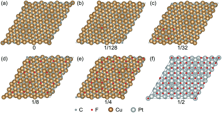
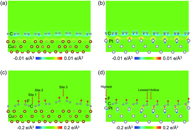
The FGr/Cu(111) and FGr/Pt(111) under a serial of fluorine coverages are present in Fig. 1. Fig. 1a–e represent the FGr on Cu(111) with the fluorine coverages of 0, 1/128, 1/32, 1/8 and 1/4, respectively. Fig. 1f represents the FGr on Pt(111) with the fluorine coverage of 1/2. Here we find one significant difference between the Cu(111) and Pt(111) is that the saturation fluorine coverage of Gr/Cu(111) is 1/4, while the fluorine coverage of Gr/Pt(111) could reach up to 1/2. The averaged binding energies of each F atom with a serial of fluorine coverages corresponding to Fig. 1b–f are −1.8 eV per atom, −1.57 eV per atom, −1.12 eV per atom, −1.33 eV per atom and −1.27 eV per atom, respectively. The intensive binding energy of F atom indicating the Cu(111) and Pt(111) substrates could enhance the fluorination activity of graphene and this activity weakens with the increase of fluorine coverage on Gr/Cu(111).The corresponding graphene's carbon skeletons after fluorination are shown in Fig. 2, from which we can observe the obvious enhanced geometrical corrugations as the occurrence of sp2–sp3 transition in graphene. Locally distributed fluorination sites will stretch up the graphene and result in distortion as shown in Fig. 2b and c. Even the uniform distribution of F atoms could preserve the moiré topography of graphene as shown in Fig. 2d and e, the geometrical corrugations are still more than 6 times larger than that of graphene without fluorination (Fig. 2a). While for the FGr/Pt(111) with the fluorine coverage of 1/2, the geometrical corrugation of graphene (1.52 Å) is much smaller than those on Cu(111), indicating that the Pt(111) could well confine the geometrical corrugation of graphene after fluorination. Similar behavior could also be observed for the case of FGr/Pt(111) (1/128 coverage) as shown in Fig. S1,† and the geometrical corrugation of graphene is only 0.42 Å, which is much smaller than that of FGr/Cu(111) with the same coverage (1.66 Å). The interfacial charge transfer distributions could help us to interpret the effects of substrates on the geometrical morphologies of graphene after fluorination. The interfacial charge transfer between graphene and Cu(111) is much weaker than that between graphene and Pt(111) as shown in Fig. 3a and b, which is also verified by the interfacial interaction energies of Gr/Cu(111) (−25.32 meV Å−2) and Gr/Pt(111) (−30.49 meV Å−2). The charge transfer distributions between the FGr (1/4 coverage) and Cu(111), and between the FGr (1/2 coverage) and Pt(111) are illustrated in Fig. 3c and d, which indicate that fluorination could enhance the interfacial interaction between graphene and substrate due to the chemical modification of graphene arising from fluorination. From Fig. 3d, we could also observe that the charge transfer between the FGr and Pt(111) (−385.04 meV Å−2) is much stronger than that between the FGr and Cu(111) (−35.45 meV Å−2) as shown in Fig. 3c. The more intensive interfacial reactivity between the FGr and Pt(111) could well confine the out-of-plane deformation of graphene induced by fluorination and also behave as a driving force to allow the fluorine coverage on Gr/Pt(111) to reach up to 1/2. In addition, the tight binding between the FGr and Cu(111) or Pt(111) substrate could effectively suppress the occurrence of puckering effect, which happens when graphene weakly bounds to the substrate.3,33 Puckering effect can give rise to the higher friction on graphene due to larger effective contact area, which is different from the mechanism in this study. Thus, our calculations indicate that the large geometrical corrugation could be introduced into graphene after fluorination, but a stronger interacting substrate could well confine the geometrical corrugation of graphene after fluorination.
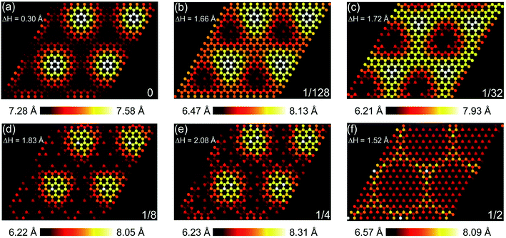 | ||
| Fig. 2 Geometrical corrugations of graphene sheet with several fluorine coverages presented in Fig. 1 and the structures are enlarged with 2 × 2 expansion. The color reflects the topography of graphene. The height of bottom layer is set as reference. (a)–(f) Fluorine coverages of 0, 1/128, 1/32, 1/8, 1/4 and 1/2, respectively. | ||
3.2 Effects of substrate on the sliding potential energy corrugation of FGr
For investigating the frictional properties of FGr/Cu(111) with saturation fluorine coverage 1/4, we utilized an Ar atom to indent on three selected sites as shown in Fig. 3c. The indentation method obtaining the adsorption energy and normal load of the Ar atom simultaneously could help us to obtain its potential energy at the indentation site under fixed tip height. Site 1 is at the center of six C atoms at the domain wall region. Site 2 is on the top of F atom at the domain wall region. Site 3 is at the bridge site of two F atoms at the domain region. From the potential energy corrugation differences between site 1 and site 2, and between site 1 and site 3, the atomic scale and the moiré superlattice scale frictional properties could be estimated. The relaxed atomic structures during the Ar atom indenting and the height of the Ar atom at the selected sites are shown in Fig. 4. During the geometrical relaxation, the Ar atom and bottom two Cu layers were fixed and the rest top Cu layer and FGr layer were allowed to relax until the forces on all the relaxed atoms were less than 0.02 eV Å−1.The corresponding adsorption energies and heights of the Ar atom during the indentation processes are shown in Fig. 5a and b. Through the interpolation method we obtained the adsorption energies and heights of Ar atom under the normal loads of 0.25 nN, 0.5 nN, 0.75 nN, 1.0 nN, 1.25 nN and 1.5 nN, respectively. The adsorption energy differences and potential energy differences between the Ar atom indenting at site 1 and site 2, and at site 1 and site 3 are illustrated at Fig. 5c. The results in Fig. 5c emphasize the importance of geometrical corrugation on contributing to the potential energy corrugation both in atomic scale and moiré superlattice scale.
 | ||
| Fig. 5 Estimation of the potential energy corrugation of an Ar atom sliding at the surface of FGr/Cu(111) (1/4 coverage). (a) Evolution of adsorption energies of the Ar atom when indenting at the selected sites in Fig. 3c. (b) Relationship between normal loads and heights of the Ar atom during indenting at the selected sites. The height of bottom Cu layer is set as reference. (c) The adsorption energy differences and potential energy differences of the Ar atom indenting at the selected sites under the normal loads of 0.25 nN, 0.5 nN, 0.75 nN, 1.0 nN, 1.25 nN and 1.5 nN, respectively. | ||
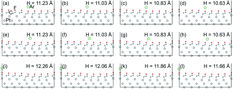
The calculation of indenting an Ar atom on the selected sites (indicated in Fig. 3d) of FGr/Pt(111) (1/2 coverage) were also performed. The relaxed atomic structures during the Ar atom indenting and adopted heights of Ar atom are shown in Fig. 6. Fig. 7a and b present the evolutions of adsorption energies and heights of the Ar atom during indenting at the selected sites. Similar method to the indentation of an Ar atom on FGr/Cu(111), we obtained the atomic scale and moiré superlattice scale of adsorption energy differences and potential energy differences of the Ar atom sliding on FGr/Pt(111) under the normal loads of 0.25 nN, 0.5 nN, 0.75 nN, 1.0 nN, 1.25 nN, and 1.50 nN as shown in Fig. 7c. From Fig. 7c, we can observe that the atomic scale potential energy corrugation does not enhance remarkably as that of indenting on FGr/Cu(111) in Fig. 5c. The reason could be that one side fully fluorination of graphene on Pt(111) could effectively reduce the Ar atom height difference between the lowest F atom site and hollow site. In addition the moiré superlattice scale potential energy corrugation increases remarkably, but its magnitude is obviously smaller than that of FGr/Cu(111), since the geometrical corrugation of FGr/Pt(111) is much smaller than that of FGr/Cu(111). The above results further illustrate that the reactivity between the graphene and substrate significantly influences the geometrical corrugation of graphene after fluorination as a result determining the friction of FGr. The DFT calculation results are consistent with previous MD simulations, which found the atomic roughness induced by hydrogenation is the primary cause of the friction enhancement and excluded other proposed mechanisms, e.g., adhesion and rigidity. The simulations also found that friction does not monotonically increase with hydrogen coverage on the graphene surface.14
 | ||
| Fig. 7 Estimation of the potential energy corrugation of an Ar atom sliding at the surface of FGr/Pt(111) (1/2 coverage). (a) Evolution of adsorption energies of the Ar atom when indenting at the selected sites in Fig. 3d. (b) Relationship between normal loads and heights of the Ar atom during indenting at the selected sites. The height of bottom Pt layer is set as reference. (c) The adsorption energy differences and potential energy differences of the Ar atom indenting at the selected sites under the normal loads of 0.25 nN, 0.5 nN, 0.75 nN, 1.0 nN, 1.25 nN and 1.5 nN, respectively. | ||
Due to the inert characteristic of the Ar atom, it is hard to estimate the effects of the chemical interaction between the tip and the sliding surface on the friction of FGr. With respect to a more reactive tip, the dominant factor that influences the surface friction of FGr also needs to be clarified. In the following calculations, we adopted a 10-atom Ir tip to slide on the surface of FGr/Pt(111) (1/2 coverage) and unraveled the effects of tip characteristic on the frictional properties of FGr.
3.3 Effects of tip characteristic on the surface frictional properties of FGr
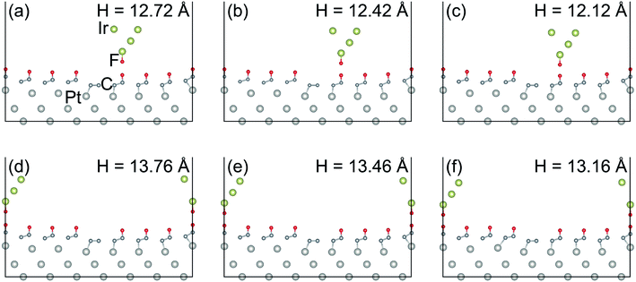
For the indentation of the 10-atom Ir tip on the FGr/Pt(111), the 10-atom Ir tip was firstly relaxed and then indented on the lowest F atom and highest F atom (as shown in Fig. 3d), respectively. During the calculations, the 10-atom Ir tip and bottom two Pt(111) layers were fixed and the rest top Pt(111) layer and FGr layer were allowed to relax until the forces on all the relaxed atoms were less than 0.02 eV Å−1.The relaxed atomic structures during the 10-atom Ir tip indenting on the lowest F atom and highest F atom of FGr/Pt(111) are shown in Fig. 8. Here, the tip height refers to the height of Ir tip apex atom. Interestingly, we find the F atom beneath the Ir tip transfers from the graphene to the tip. The adsorption energies and heights of the 10-atom Ir tip during the indentation processes in Fig. 8 are shown in Fig. 9a and b, respectively. From Fig. 8f–j, we find the transfer of F atom from the graphene to the Ir tip will reduce the height difference between the tip at the lowest and highest F atoms under normal loads, as a result decreasing the contribution of the work against the normal load during sliding. While the adsorption energy difference between the tip at the lowest and highest F atoms increases remarkably as shown in Fig. 9a. By the similar interpolation method, the adsorption energy differences and potential energy differences during the 10-atom Ir tip indenting at the selected sites under the normal loads of 0.25 nN, 0.5 nN, 0.75 nN, 1.0 nN, 1.25 nN, and 1.50 nN are shown in Fig. 9c, respectively. Results in Fig. 9c reveal the importance of tip–surface interaction on contributing the friction during the tip sliding, and the potential energy corrugation difference decreases obviously than that of the Ar tip (Fig. 7c) as the geometrical corrugation difference decreases arising from the tip–surface interaction. However, the transfer of F atom from the graphene to the Ir tip causes the sliding of tip on the surface of FGr/Pt(111) complex.
3.4 Sliding frictional properties of the 10-atom Ir tip after a F atom transferred on it
Considering the transfer of F atom to the 10-atom Ir tip, we further calculated the frictional properties of 10-atom Ir tip (with a F atom transferred on it) sliding on the FGr/Pt(111). We selected the 10-atom Ir tip indenting at the lowest F as initial position as its energy minimum. Firstly, the tip was lifted on the surface of FGr. Then we utilized the 10-atom Ir tip (with a F atom transferred on it) to indent on the lowest and highest F atoms on the FGr. The relaxed atomic structures during the indenting processes are shown in Fig. 10. The above processes include two steps of energy dissipations. One step is lifting the tip onto the surface of FGr and the other one is the Ir tip (with a F atom transferred on it) sliding on the FGr.The evolutions of adsorption energies and heights of Ir tip during indentation at the selected sites are presented in Fig. 11a and b. For convenience in the calculations of Ead (Ead = Etotal − Esubstrate − Etip), we set the Esubstrate as the energy of FGr on Pt(111), and Etip as the energy of 10-atom Ir tip, which are consistent with the calculations of Fig. 9. As a comparison, we also show the results of 10-atom Ir tip indenting on the lowest site of FGr on Pt(111) as the reference. Fig. 11c indicates that the difference of adsorption energy is reduced and the work against the normal load to lift the Ir tip increases. Especially, to lift the Ir tip (after a F atom transferred on it) on the lowest F atom of FGr as shown in Fig. 10a–c will consume large amount of work resulting in a remarkably enhanced potential energy corrugation, which is much larger than that of the Ar tip as shown in Fig. 7c. With respect to the Ir tip (with a F atom transferred on it) sliding on the FGr, the geometrical corrugation starts to play a crucial role in contributing friction enhancement. From Fig. 11c, we could also find that potential energy corrugation difference of lifting the Ir tip (with a F atom transferred on it) onto the surface of FGr is much larger than that of the tip (with a F atom transferred on it) sliding on the FGr. Our simulations reveal that the F atom transfer to the tip will reduce the adsorption energy difference during the tip sliding, while enhance the work against the normal load to lift the tip. The tip–surface interaction could tune the sliding atomic details between the tip and surface, which further influences the frictional characteristic.
Therefore, the interactive tip could increase the adsorption energy difference and reduce the geometrical corrugation. The DFT simulations also reveal that when the tip–surface interaction is strong enough, the F atom will transfer to the tip. Then lifting the tip on the surface of FGr will be a significant energy dissipation pathway. The geometrical corrugation will become the dominant factor for the surface friction of the fluorinated tip sliding on the FGr. Thus, to suppress the geometry corrugation is a promising avenue to preserve the superior frictional properties of graphene after fluorination, such as confining the out-of-plane deformation of graphene via the anchoring effect from the moiré superstructure.18 The results of this study could also be generalized for other types of chemically modified graphene, e.g., oxidized graphene and hydrogenated graphene. Since all of these chemical modifications could enhance the geometrical corrugation and bending stiffness of graphene similarly.14,34 As a result, the geometrical corrugation subsequently plays a key role in determining the surface friction of chemically modified graphene when a tip sliding on it.
4. Conclusions
In this study, the DFT calculations reveal the effects of substrate and tip characteristics on the surface friction of FGr. The calculation results indicate that the fluorination will remarkably increase the geometrical corrugation of graphene on Cu(111) and Pt(111). In addition, the geometrical corrugation could be suppressed by stronger reactivity between graphene and substrate. Then the calculations of indenting an Ar atom at the FGr on Cu(111) and Pt(111) illustrate the geometrical corrugation contributes dominantly to the sliding potential energy corrugation. Considering the characteristic of the tip, we also investigated the sliding of a 10-atom Ir tip. Interestingly, the F atom beneath the tip transfers from graphene to the Ir tip. As a result, the fluorinated Ir tip will slide on the surface of FGr and the work against the normal load to lift the tip over the geometrical corrugation becomes the dominant role in determining the surface friction. Tuning the atomic details and reducing the geometrical corrugation of the fluorinated surface are crucial to maintain the surface friction of chemical modified graphene.Conflicts of interest
There are no conflicts of interest to declare.Acknowledgements
The authors would like to acknowledge the support of the National Natural Science Foundation of China (Grant No. 51705017, U1706221) and the Fundamental Research Funds for the Central Universities.References
- O. Hod, E. Meyer, Q. Zheng and M. Urbakh, Nature, 2018, 563, 485–492 CrossRef CAS PubMed.
- E. Koren, E. Lörtscher, C. Rawlings, A. W. Knoll and U. Duerig, Science, 2015, 348, 679–683 CrossRef CAS PubMed.
- C. Lee, Q. Li, W. Kalb, X.-Z. Liu, H. Berger, R. W. Carpick and J. Hone, Science, 2010, 328, 76–80 CrossRef CAS PubMed.
- S. Li, Q. Li, R. W. Carpick, P. Gumbsch, X. Z. Liu, X. Ding, J. Sun and J. Li, Nature, 2016, 539, 541–545 CrossRef CAS PubMed.
- D. Berman, A. Erdemir and A. V. Sumant, ACS Nano, 2018, 12, 2122–2137 CrossRef CAS PubMed.
- D. Berman, A. Erdemir and A. V. Sumant, Mater. Today, 2014, 17, 31–42 CrossRef CAS.
- T. W. Scharf and S. V. Prasad, J. Mater. Sci., 2013, 48, 511–531 CrossRef CAS.
- C. Donnet and A. Erdemir, Tribol. Lett., 2004, 17, 389–397 CrossRef CAS.
- S. Zhang, T. Ma, A. Erdemir and Q. Li, Mater. Today, 2019, 26, 67–86 CrossRef CAS.
- S. Kwon, J.-H. Ko, K.-J. Jeon, Y.-H. Kim and J. Y. Park, Nano Lett., 2012, 12, 6043–6048 CrossRef CAS PubMed.
- J.-H. Ko, S. Kwon, I.-S. Byun, J. S. Choi, B. H. Park, Y.-H. Kim and J. Y. Park, Tribol. Lett., 2013, 50, 137–144 CrossRef CAS.
- Q. Li, X.-Z. Liu, S.-P. Kim, V. B. Shenoy, P. E. Sheehan, J. T. Robinson and R. W. Carpick, Nano Lett., 2014, 14, 5212–5217 CrossRef CAS PubMed.
- G. Fessler, B. Eren, U. Gysin, T. Glatzel and E. Meyer, Appl. Phys. Lett., 2014, 104, 041910 CrossRef.
- Y. Dong, X. Wu and A. Martini, Nanotechnology, 2013, 24, 375701 CrossRef PubMed.
- V. Georgakilas, M. Otyepka, A. B. Bourlinos, V. Chandra, N. Kim, K. C. Kemp, P. Hobza, R. Zboril and K. S. Kim, Chem. Rev., 2012, 112, 6156–6214 CrossRef CAS PubMed.
- T. Kuila, S. Bose, A. K. Mishra, P. Khanra, N. H. Kim and J. H. Lee, Prog. Mater. Sci., 2012, 57, 1061–1105 CrossRef CAS.
- J. Liu, Y. Qi, Q. Li, T. Duan, W. Yue, A. Vadakkepatt, C. Ye and Y. Dong, Carbon, 2019, 142, 363–372 CrossRef CAS.
- X. Zheng, L. Gao, Q. Yao, Q. Li, M. Zhang, X. Xie, S. Qiao, G. Wang, T. Ma, Z. Di, J. Luo and X. Wang, Nat. Commun., 2016, 7, 13204 CrossRef CAS PubMed.
- Y. Qi, J. Liu, Y. Dong, X.-Q. Feng and Q. Li, Carbon, 2018, 139, 59–66 CrossRef CAS.
- L. Gao, Y. Ma, Y. Liu, A. Song, T. Ma, Y. Hu, Y. Su and L. Qiao, J. Phys. Chem. C, 2017, 121, 21397–21404 CrossRef CAS.
- G. Kresse and J. Furthmüller, Phys. Rev. B: Condens. Matter Mater. Phys., 1996, 54, 11169–11186 CrossRef CAS PubMed.
- P. E. Blöchl, Phys. Rev. B: Condens. Matter Mater. Phys., 1994, 50, 17953–17979 CrossRef PubMed.
- J. P. Perdew, K. Burke and M. Ernzerhof, Phys. Rev. Lett., 1996, 77, 3865 CrossRef CAS PubMed.
- J. Klimeš, D. R. Bowler and A. Michaelides, J. Phys.: Condens. Matter, 2010, 22, 022201 CrossRef PubMed.
- J. Klimeš, D. R. Bowler and A. Michaelides, Phys. Rev. B: Condens. Matter Mater. Phys., 2011, 83, 195131 CrossRef.
- H. Tetlow, J. P. de Boer, I. J. Ford, D. D. Vvedensky, J. Coraux and L. Kantorovich, Phys. Rep., 2014, 542, 195–295 CrossRef CAS.
- L. Gao, J. R. Guest and N. P. Guisinger, Nano Lett., 2010, 10, 3512–3516 CrossRef CAS PubMed.
- J. T. Robinson, J. S. Burgess, C. E. Junkermeier, S. C. Badescu, T. L. Reinecke, F. K. Perkins, M. K. Zalalutdniov, J. W. Baldwin, J. C. Culbertson, P. E. Sheehan and E. S. Snow, Nano Lett., 2010, 10, 3001–3005 CrossRef CAS PubMed.
- A. Vanossi, N. Manini, M. Urbakh, S. Zapperi and E. Tosatti, Rev. Mod. Phys., 2013, 85, 529–552 CrossRef CAS.
- A. Socoliuc, R. Bennewitz, E. Gnecco and E. Meyer, Phys. Rev. Lett., 2004, 92, 134301 CrossRef CAS PubMed.
- W. Zhong and D. Tománek, Phys. Rev. Lett., 1990, 64, 3054 CrossRef CAS PubMed.
- L. Gao, X. Chen, Y. Ma, Y. Yan, T. Ma, Y. Su and L. Qiao, Nanoscale, 2018, 10, 10576–10583 RSC.
- J. S. Choi, J.-S. Kim, I.-S. Byun, D. H. Lee, M. J. Lee, B. H. Park, C. Lee, D. Yoon, H. Cheong, K. H. Lee, Y.-W. Son, J. Y. Park and M. Salmeron, Science, 2011, 333, 607–610 CrossRef CAS PubMed.
- L.-F. Wang, T.-B. Ma, Y.-Z. Hu and H. Wang, Phys. Rev. B: Condens. Matter Mater. Phys., 2012, 86, 125436 CrossRef.
Footnote |
| † Electronic supplementary information (ESI) available. See DOI: 10.1039/d0ra00770f |
| This journal is © The Royal Society of Chemistry 2020 |

