 Open Access Article
Reduction of 4-nitrophenol and 2-nitroaniline using immobilized CoMn2O4 NPs on lignin supported on FPS
Yuning Chena,
Li Feng *a and
Seyed Mohsen Sadeghzadeh
 *b
*b
aSchool of Civil and Transportation Engineering, Guangdong University of Technology, No. 100, Waihuan Xi Road, Guangzhou Higher Education Mega Center, Panyu District, Guangzhou 510006, Guangdong, China. E-mail: fl19860314@126.com
bYoung Researchers and Elite Club, Neyshabur Branch, Islamic Azad University, Neyshabur, Iran. E-mail: seyedmohsen_sadeghzadeh@yahoo.com
First published on 22nd May 2020
Abstract
In the present work, fibrous phosphosilicate (FPS) was functionalized by using octakis[3-(3-aminopropyltriethoxysilane)propyl]octasilsesquioxane (APTPOSS) groups that act as strong performers. In this regard, the nanoparticles of CoMn2O4 were dispersed, properly, on FPS microsphere (CoMn2O4/APTPOSS@FPS) fibers. Agricultural and industrial waste waters contain nitrophenols. They are amongst the most common organic pollutants. In water, low concentrations are harmful to human health and aquatic life owing to the potential mutagenic and carcinogenic influences of nitrophenols. 4-Nitrophenol (4-NP), as well as 2-nitroaniline (2-NA), are known hazardous toxic waste contaminants and are included in the United States Environmental Protection Agency (USEPA) list. Thus, to eliminate them, novel methods are necessary. In addition, o-phenylenediamine (o-PDA) and 4-aminophenol (4-AP) are considered as significant intermediates for the synthesis of dyes and drugs, which are synthesized from 2-NA and 4-NP. Nanoparticles of CoMn2O4/APTPOSS@FPS utilized for the reduction of 2-NA and 4-NP, increase the efficiency of the reaction with considerable chemoselectivity. The results showed that the P and O atoms of lignin-FPS gold nanoparticles (NPs) were stable and the morphology and structure of FPS increased the catalytic activity.
Introduction
In recent years, green chemistry has been highly considered as being able to overcome environmental pollution originating from the world's population.1–7 In aqueous solutions, the approach of reducing harmful organic solvents for transforming organic debris in reusable mixtures by using less toxic means has attracted a great response from scientific centers. Many studies have been performed to determine the availability of nitroaromatic materials. Agricultural and industrial waste waters contain nitrophenols, which are amongst the most common organic pollutants.8,9 Low concentrations of nitrophenols in water are harmful to human health and aquatic life owing to the potential carcinogenic and mutagenic effects of nitrophenols.10,11 Therefore, 2-nitroaniline (2-NA) and 4-nitrophenol (4-NP), which are hazardous and toxic waste pollutants, are included on the United States Environmental Protection Agency (USEPA) list.12–16 Therefore, developing effective approaches to eliminate them is an important task. In addition, for the production of dyes and drugs that can be synthesized from 4-NP and 2-NA, o-phenylenediamine (o-PDA) and 4-aminophenol (4-AP) are important intermediates.17–21It has been reported in the literature that in comparison to transition metal oxides such as Co and Mn, valuable metal catalysts such as Pt, Pd, Au, and Ag demonstrate a greater activity.22–26 However, valuable metal catalysts have many inevitable drawbacks such as a tendency to be easily poisoned, there are limited resources, and they have a high cost. As they have a high specific surface area, are exotic, and have reduced dimensionality properties, two-dimensional nanosheets have been used for the design of novel electrocatalysts for carbon dioxide reduction.27–34 Borophene has been introduced as a novel 2D material under active investigation owing to its fascinating and diverse attributes, as well as its potential.35 It has been demonstrated that the properties of borophene can be improved and further developed by alloying it, amongst other factors. Allowing the opportunity to design novel functional catalysts or materials.
Significant efforts have been made for the expansion of efficient transition metal oxide catalysts with a high thermal stability and low costs for adapting noble metal catalysts.36–39 Manganese and cobalt are recognized as the most promising among the transition metal oxides owing to their low price and adequate activities at relatively low temperatures. For toluene and benzene oxidation, scholars propose the following catalytic activity order: Mn3O4 > α-Mn2O3 > β-MnO2. For total oxidation, Mn with a high valence is more active. The further addition of alkaline earth metals and alkali metals enhances the catalytic performance.40–43
The utilization of surfactants on soft templates simplifies the mesoporous phosphosilicate produced and the phosphosilicate fibers have a dendrimetric morphology. Phosphosilicates with this specific morphology were tested as support materials. For the reactants, in order to access the functional materials in terms of the adsorption and catalysis approaches, the apparent expansion of these silicas indicated a higher surface area. Moreover, fibrous phosphosilicate (FPS), which has intrinsic mesoporous properties, is thermally stable, and possesses a high activity. The FPS produced requires a microemulsion method that includes water, oils, and surfactants. Moreover, the FPS morphology and particle size can be managed by the use of many co-solvents and co-surfactants.44–51
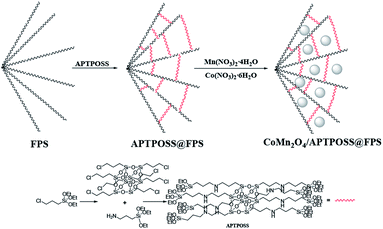
In this way, the organic groups were replaced by silica groups. For proper stabilization and immobilization of the metal catalysts, we showed that octakis[3-(3-aminopropyltriethoxysilane)propyl]octasilsesquioxane (APTPOSS) is a highly efficient and powerful support. With this replacement, the strength of the catalytic structure was improved. This catalyst support was fabricated by FPS obstruction using APTPOSS (APTPOSS@FPS). Actually, APTPOSS@FPS is a nano labyrinth for holding the nanoparticle. It was determined that this particular property can be very beneficial for the design of silica-supported catalysts. The availability of the active sites may be considerably improved. In the present work, APTPOSS@FPS is utilized as a novel supporting material for stabilizing CoMn2O4 nanoparticles (NPs) and for achieving a CoMn2O4/APTPOSS@FPS nanocatalyst along with an improved high surface area and accessibility for the active sites. Moreover, as seen in Scheme 1, its utility was described for the catalytic reduction of 2-NA and 4-NP and it can be separated from the reaction mixture for reuse.
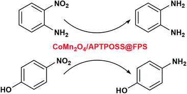 | ||
| Scheme 1 Reduction of 4-NP and 2-NA from alkylphenols in the presence of the CoMn2O4/APTPOSS@FPS NPs. | ||
Experimental
General approach for the preparation of the FPS nanoparticles
Tetraethyl orthosilicate (TEOS) (2.08 g) and tripolyphosphate (TPP) (3.67 g) were dissolved in a solution of cyclohexane (30 mL) and 1-pentanol (1.5 mL). A stirred solution of cetylpyridinium bromide (CPB 1 g) and urea (0.5 g) in water (30 mL) was then added. The resulting mixture was continually stirred for 45 min at room temperature and then placed in a Teflon-sealed hydrothermal reactor and heated at 120 °C for 5 h. The FPS was then isolated by centrifugation, washed with deionized water and acetone, and dried in a drying oven.45Synthesis of APTPOSS
Under a nitrogen atmosphere, 2 mmol ClPOSS and 20 mmol 3-aminopropyltriethoxysilane were transferred to a reaction vessel and the reaction solution was stirred at a temperature of 100 °C for 48 h. After that the mixture was cooled to 25 °C temperature and the solution was filtered and then washed with acetone and methanol.General approach for the synthesis of nanoparticles of APTPOSS@FPS
2 mmol of the FPS NPs and 20 mL THF were mixed together in a beaker. After that, 20 mmol of NaH was dispersed into the mixture using ultrasonication. 0.5 g APTPOSS was added at 25 °C and stirred at 60 °C for another 16 h. The resulting products were gathered and then washed repeatedly using deionized water and ethanol. After that, the products were dried under a vacuum at a temperature of 60 °C for 2 h and stored for further use.General approach for the synthesis of nanoparticles of CoMn2O4/APTPOSS@FPS
FPS/APTPOSS (0.1 g), 1.1 mL of aqueous 45 mM Mn(NO3)2·4H2O and 45 mM Co(NO3)2·6H2O were dissolved in distilled water. Then, 0.002 mol citric acid was added to the mixed solution. The pH of this solution was set to 9 using tetraethylenepentamine (TEPA) added drop-wise. In the second step, 0.002 mol of ethylene glycol was added to the solution as an agent for esterification. The synthesis of the porous solid mass can be enabled by enhancing the temperature and the evaporation of the gel-like solution. Ferula asafoetida gum was (1 g) added to achieved powders and these were calcinated at a temperature of 700 °C for around 3 h.General approach for the reduction of 4-NP
In the first step, 40 μL of the aqueous 4-NP solution, 1.26 × 10⁻² mol L−1, was added to 2.5 mL water. After that, it was mixed with a freshly prepared aqueous 0.5 M NaBH4 solution and a deep yellow solution was obtained. 0.4 mg of the catalyst was added into the obtained yellow solution and when this solution became colorless, the reaction was complete. The reaction progress was monitored using UV-vis absorption spectroscopy of the reaction mixture.General approach for the reduction of 2-NA
A constant amount of the catalyst (1 mg) was added to 2.5 mL water, and this was then mixed with a 2-NA aqueous solution (40 μL, 1.26 × 10⁻² mol L−1) and a 0.5 M NaBH4 solution was rapidly injected while stirring. The mixture color gradually vanished, showing the 2-NA reduction. By measuring the UV-vis absorption spectra of the reaction mixture, the reaction trend was monitored.Results and discussion
The nanoparticles of CoMn2O4/APTPOSS@FPS are produced using a simplistic three step method. Firstly, FPS is made by the simultaneous condensation and hydrolysis of TPP as well as TEOS. After that, the FPS fibers possess many P–OH and Si–OH groups on their surfaces. Therefore, to form APTPOSS@FPS, the FPS can be easily functionalized with APTPOSS. Lastly, the APTPOSS groups on the FPS can act as aggregation centers to enhance the metal NPs on the surface of FPS. In the case of FPS (Scheme 2), to retain the nanoparticles, we determined the best combination of the three structure of APTPOSS. These were characterized using energy-dispersive X-ray spectroscopy (EDX), scanning electron microscopy (SEM), X-ray diffractometry (XRD), atomic force microscopy (AFM), and transmission electron microscopy (TEM) analysis. It is important to note that the authenticity of the CoMn2O4/APTPOSS@FPS synthesis is mentioned in our previous study.Fig. 1 shows the field emission scanning electron microscopy (FESEM) schema of FPS. It was determined that the FPS sample includes wall-like domains (as seen in Fig. 1a) and the wall sizes were fixed (Fig. 1c). Further investigation of the mentioned schemas shows that the material had dendrimetric fibers possessing a thickness in the range of 10–15 nm. It was adjusted in three dimensions for forming walls, which can easily facilitate availability owing to the existing high surface area. The fibers of FPS consist of different groups of Si–OH and P–OH on these levels. The groups of Si–OH and P–OH over the surface may act as association centers in the case of the growth of NPs of CoMn2O4 over the FPS level. Fig. 1b and d show the FESEM and TEM images in the case of the CoMn2O4 NPs. As can be seen, the as-prepared metal NPs were spherical and did not show obvious aggregation. The diameter of the NPs of CoMn2O4 was about 10 nm. It should be noted that the morphology of the nanoparticles is near-wall.
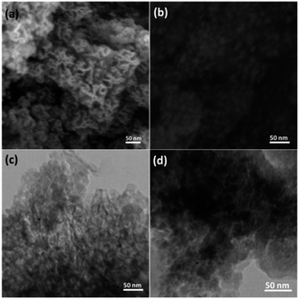 | ||
| Fig. 1 FESEM images of the FPS NPs (a) and CoMn2O4/APTPOSS@FPS NPs (b); and TEM images of the FPS NPs (c) and CoMn2O4/APTPOSS@FPS NPs (d). | ||
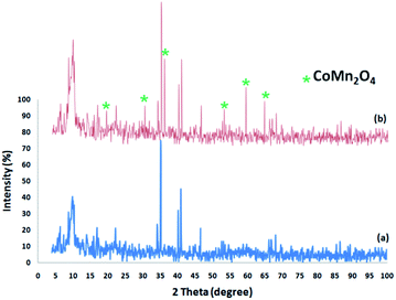
Fig. 2 shows the XRD spectra of the FPS and CoMn2O4/APTPOSS@FPS NPs. The XRD spectra of the FPS NPs indicates a number of crystalline peaks as stated in a previous study.52 As seen in Fig. 2, the total diffraction peaks completely matched those of the pure fluorite CoMn2O4 and no impurities exist in this image.53 For the CoMn2O4/APTPOSS@FPS nanoparticles, new peaks reflecting the CoMn2O4 crystal confirmed the proper growth of the CoMn2O4 particles on the FPS surface.
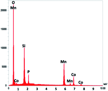
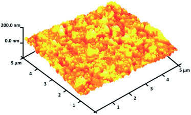
As seen in Fig. 3, to obtain a high level of detail, the EDX spectrum was characterized to reveal the purity of the CoMn2O4/APTPOSS@FPS nanoparticles, which have a fibrous shape. The EDX picture additionally proved the presence of P and Si in similar weight ratios affirming the proper cooperation of TPP and TEOS in the structure of FPS. The existence of O, Mn, and Co demonstrates that the fibrous CoMn2O4 specimen has been fabricated. The roughness of the nanoparticles of CoMn2O4/APTPOSS@FPS was determined using AFM analysis. Fig. 4 shows the topographic image. As observed in Fig. 4, the regions with a greater height, shown using the brighter yellowish white color, improved with the reducing thickness (T)/width (W), indicating the enhancement in the roughness of the catalyst.
For FPS, the N2 adsorption–desorption isotherms of the nanostructure of FPS demonstrated a specific type IV curve. The Barrett–Joyner–Halenda (BJH) pore diameter, total pore volume, and Brunauer–Emmett–Teller (BET) surface area, were found to be 7.92 nm, 0.86 cm3 g−1, and 213 m2 g−1 respectively, while the corresponding results were 7.21 nm, 0.79 cm3 g−1, and 204 m2 g−1 for APTPOSS@FPS. In comparison to APTPOSS@FPS, no considerable change was seen in the pore volumes of FPS. Table 1 shows that this can be ascribed to the fibrous structure. The formation of the CoMn2O4 NPs caused a further decrease, however, there was a less pronounced reduction in the porosity characteristics (Table 1, entry 3). The formation of CoMn2O4 NPs upon reduction caused further, but less pronounced, reduction of the porosity characteristics. The reduction of the pore volume upon the formation of particles was marked, in particular, for CoMn2O4/APTPOSS@FPS from 0.42 cm3 g−1 and APTPOSS@FPS to 0.79 cm3 g−1. The obtained result indicates that the CoMn2O4 NPs form directly in the APTPOSS@FPS derivative pores.
| Catalyst | SBET (m2 g−1) | Vt (cm3 g−1) | DBJH (nm) |
|---|---|---|---|
| FPS | 213 | 0.86 | 7.92 |
| APTPOSS@FPS | 204 | 0.79 | 7.21 |
| CoMn2O4/APTPOSS@FPS | 124 | 0.42 | 1.34 |
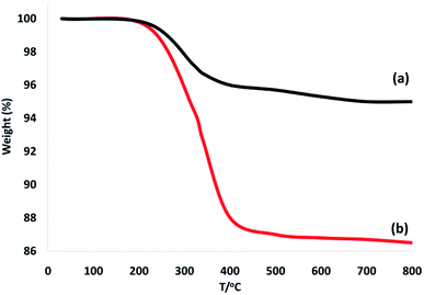
To confirm the thermal stability of the CoMn2O4/APTPOSS@FPS NPs, thermogravimetric analysis was performed under temperatures in the range of 25 to 800 °C (Fig. 5). The weight loss below the temperature of 250 °C was caused by the elimination of the chemisorbed and physisorbed solvent over the silica material surface. The provided organic weight losses for CoMn2O4/APTPOSS@FPS are 7.8%. Based on these results, the good grafting yields of the organic compounds on the NPs were corroborated.
In addition, the FPS spectra revealed a further peak at about 1483 cm−1 that can be ascribed to the phosphate moiety obtained from TPP. In the FPS spectrum, the main peak was the additional peak observed at 1232 cm−1 that can be attributed to the –P![[double bond, length as m-dash]](https://www.rsc.org/images/entities/char_e001.gif) O stretching vibration showing the presence of the phosphate group. The shoulder at 1108 cm−1 and the band at 963 cm−1 could be because of the longitudinal optimal (LO) and transverse optical (TO) modes of the asymmetric stretching vibration of the Si–O–P bonds, respectively. The bands at around 724 and 795 cm−1 are considered to be a result of the asymmetric stretching of the bridging oxygen atoms that are bonded to the phosphorus atom, which provide appropriate proof of the presence of TPP and TEOS in the FPS structure (Fig. 6a). The bands observed at 2956 cm−1 are assigned to the C–H stretching of the aliphatic moieties (Fig. 6b). These results indicated that APTPOSS had been successfully introduced onto the surface of the FPS.
O stretching vibration showing the presence of the phosphate group. The shoulder at 1108 cm−1 and the band at 963 cm−1 could be because of the longitudinal optimal (LO) and transverse optical (TO) modes of the asymmetric stretching vibration of the Si–O–P bonds, respectively. The bands at around 724 and 795 cm−1 are considered to be a result of the asymmetric stretching of the bridging oxygen atoms that are bonded to the phosphorus atom, which provide appropriate proof of the presence of TPP and TEOS in the FPS structure (Fig. 6a). The bands observed at 2956 cm−1 are assigned to the C–H stretching of the aliphatic moieties (Fig. 6b). These results indicated that APTPOSS had been successfully introduced onto the surface of the FPS.
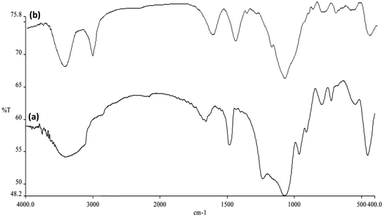 | ||
| Fig. 6 Fourier transform infrared spectroscopy (FTIR) spectra of (a) FPS NPs, and (b) CoMn2O4/APTPOSS@FPS NPs. | ||
The catalytic efficiency of the NPs of CoMn2O4/APTPOSS@FPS was studied by utilizing the 4-NP reduction to 4-AP in the presence of NaBH4 as the probe reaction. The development approach using the time duration of the reaction for the reduction of 4-NP to 4-AP was analyzed using UV-vis spectroscopy. Fig. 7a shows that the 4-NP solution represents the proper absorption peak at 300 nm and this was dramatically red-shifted to 400 nm. The addition of 1 mg of the NPs of CoMn2O4/APTPOSS@FPS to the system caused the peak intensity of 4-NP at 400 nm to decrease in addition to the concomitant enhancement of the peaks relating to 4-AP at 300 nm. This is caused by the formation of the 4-NP ion upon the addition of NaBH4. An aqueous solution of NaBH4 is basic, which induces the formation of the 4-nitrophenoxide anion in solution. Fig. 7b shows that the reaction rapidly progresses by the conversion of more than 99.8% in a reaction time of around 100 s. We also used the CoMn2O4/APTPOSS@FPS NPs to determine the catalytic reduction of 2-NA according to the above mentioned outcomes. The reduction of 2-NA can also be easily monitored because the product for the reduction was only. The reaction progress may be found by calculating the variation in the UV-vis absorbance. The 2-NA yellow colored solution presented two distinguished absorption peaks at 280 and 400 nm. By adding the NaBH4 solution, the intensity of the aforementioned peaks did not reduce. Nevertheless, as can be seen in Fig. 7c, the intensity of the above mentioned peaks gradually reduced upon the addition of NPs of CoMn2O4/APTPOSS@FPS to a NaBH4 and 2-NA mixed solution.
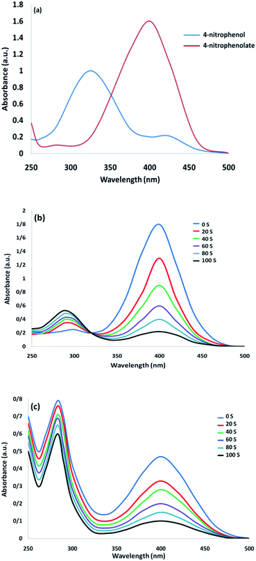 | ||
| Fig. 7 UV-vis spectra of (a) 4-NP before and after adding the solution of NaBH4; (b) the consecutive reduction of 4-NP to 4-AP; as well as (c) 2-NA to o-PDA on the CoMn2O4/APTPOSS@FPS NPs catalyst. | ||
The conversion of the reaction was predicted from the Ct/C0 and used to evaluate the relative intensity of the UV-vis absorbance (At/A0) (at 400 nm). Ct represents the 4-NP concentration at the reaction time (t). The C0 shows the primary concentration. As illustrated in Fig. 8a, the mean amount of the reaction conversions with standard deviation are given. Fig. 8b shows the linear correlation with the reaction time and the ln(Ct/C0) shows that the reaction is first-order considering the 4-NP reduction. Fig. 8b shows the linear correlation between the reaction time and ln(Ct/C0). As seen, with respect to the reduction of 4-NP, the reaction is first-order. Hence, the kinetic equation for this catalytic reduction reaction can be denoted as ln(Ct/C0) = −kt. In this relationship, t shows the reaction time and k represents the apparent first-order rate constant (s−1). For the CoMn2O4/APTPOSS@FPS nanoparticle catalyzed 4-NP reduction, the k (reaction rate constant) is predicted to be 1.83 × 10⁻² s−1. The activity parameter, k′ = k/M, is presented, for quantitative comparison, and introduced as the ratio of k to the weight of the catalyst used.54 Here, M shows the total mass of the catalyst, which is used during the reaction. Therefore, the reaction rate constants per unit mass are predicted to be 18.3 s−1 g−1 for the 4-NP reduction.
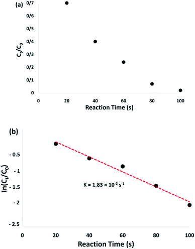 | ||
| Fig. 8 Plots of Ct/C0 (a) and ln(Ct/C0) (b) versus reaction time for the reduction of 4-NP over the CoMn2O4/APTPOSS@FPS NPs. | ||
Table 2 shows the activity factors utilized to compare the catalytic activity of CoMn2O4/APTPOSS@FPS against the Cu, Ag, Co, and Ni nanoparticle based catalysts used for the reduction of 4-NP. As observed in Table 2, k and k′ for the CoMn2O4/APTPOSS@FPS nanocatalyst are greater than those reported for the p(AMPS)-Cu, p(AMPS)-Co, and p(AMPS)-Ni catalysts. Based on previous works, the nanoparticles of p(AMPS)-Co NPs56 and p(AMPS)-Ni55 have activity factors of around 0.04 and 0.019 s−1 g−1, respectively. The rate constant k′ of p(AMPS)-Cu is equal to 0.172 s−1 g−1,57 which is greater than the TAC-Ag-1 catalyst (1.3 s−1 g−1) and the Ag doped carbon spheres catalyst (1.69 s−1 g−1), as well as the Fe3O4@SiO2–Ag NPs (7.67 s−1 g−1).58–60 The catalytic activity of the nanocatalyst of CoMn2O4/APTPOSS@FPS achieved here is 18.3 s−1 g−1, which is considerably more than the catalytic activities of the nanoparticle based catalysts introduced above; therefore the nanocatalyst of CoMn2O4/APTPOSS@FPS presents a preferable catalytic activity in terms of the reduction reactions.
| Catalysts | Catalyst (mg) | ka (s−1) | k/Mb (s−1 g−1) |
|---|---|---|---|
| a The reaction rate constant.b The reaction rate constant per total weight of catalyst used. | |||
| p(AMPS)-Co46 | 50 | 2 × 10⁻³ | 0.04 |
| p(AMPS)-Ni47 | 50 | 9.38 × 10⁻⁴ | 0.019 |
| TAC-Ag-1.0 (ref. 48) | 4.0 | 5.19 × 10⁻³ | 1.3 |
| Ag/C spheres49 | 1.0 | 1.69 × 10⁻³ | 1.69 |
| Fe3O4@SiO2–Ag50 | 1.0 | 7.67 × 10⁻³ | 7.67 |
| p(AMPS)-Cu51 | 10 | 1.72 × 10⁻³ | 0.172 |
| CoMn2O4/APTPOSS@FPS | 1.0 | 1.83 × 10⁻² | 18.3 |
Scheme 3 shows a representation of the reaction along with the activation of the hydrides on the surface of the catalyst and their transfer to the nitro group. Based on previous works, during the reduction of nitroarenes by NaBH4 catalyzed using nanoparticles of CoMn2O4, the cleavage of the B–H bond is the rate-determining step giving the CoMn2O4–H type. In the metal–hydrogen structure, the charged hydrogen, which is negative, may attack the positively charged nitrogen, quickly, which is in the nitro group of the nitrophenols. Therefore, the nitro group was decreased to the nitroso group along with the reductive addition of two hydrogen atoms to form hydroxylamine. In the last step, the hydroxylamine was further decreased to the aniline derivative.
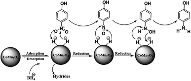 | ||
| Scheme 3 A plausible mechanism for the reduction of p-nitrophenol catalyzed by the CoMn2O4/APTPOSS@FPS NPs catalyst in the presence of NaBH4. | ||
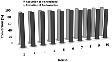
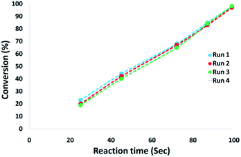
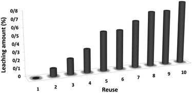
The magnetic properties of the CoMn2O4/APTPOSS@FPS NPs can improve the efficient recovery of the reaction mixture after the reaction. The activity of the recycled catalyst was evaluated over ten consecutive cycles to determine any considerable loss in the catalytic activity. Fig. 9 shows that after the reaction, the catalyst can be separated by utilizing filtration. After that we washed it with methanol and then dried it using a pump. To further evaluate the stability of the catalyst, we also performed kinetic investigations for the first 100 s in four recycling tests. Fig. 10 shows that the conversion continues to be enhanced by the increasing reaction time, reaching approximately 95% after 100 s. The kinetic curves in the case of the four recycling runs were almost overlapping each other, this shows that during these recycle runs the catalyst was not deactivated. Moreover, the CoMn2O4 value leached into the solution for the reduction of p-nitrophenol after each run was analyzed by taking into account the inductively coupled plasma (ICP). In each turn, the catalyst demonstrated very little leaching, for example, after the tenth run, 0.8% metal leaching was discovered, thus indicating the consistent reaction states as shown in Fig. 11.
Moreover, we conducted a complete analysis to clarify the heterogeneous nature of the catalyst. In the first step, we performed a hot filtration experiment in terms of the reduction of p-nitrophenol under optimum conditions. The catalyst is filteration deleted in situ after around 49% for 50 s removal. Moreover, the reactants tolerated further reactions. Our results proved that the free catalyst remnant was still slightly active, after removing the heterogeneous catalyst. A conversion of around 41% was achieved after 100 s of p-nitrophenol reduction. It was demonstrated that the catalyst acted heterogeneously in the reaction and only a slight amount of leaching occurred during the reaction. In the second step, mercury poisoning analysis was also performed to determine the heterogeneous pattern of the catalyst. Mercury(0) was imbibed as a metal for utilizing synthesis and dramatically deactivated the metal catalyst on the active surface, thus inhibiting the catalyst activity. The results of our experiments proved the activity of the heterogeneous catalyst. This analysis was performed using the above mentioned model of the reaction at optimum conditions. About 300 molar mercury was released to the reaction compound during the reaction (after 50 s). The reaction was stirred for more than 100 s and no further conversion was observed after 100 s from the catalyst being poisoned. Fig. 12 shows the kinetics scheme in the case of the reaction in the presence of Hg(0). The negative outcomes achieved from the heterogeneity experiments (hot filtration and Hg(0) poisoning) suggested that the solid catalyst was actually heterogeneous. In addition, no obtainable CoMn2O4 leaching occurred during p-nitrophenol reduction.
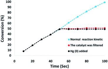 | ||
| Fig. 12 Reaction kinetics, Hg(0) poisoning, and hot filtration studies for the reduction of p-nitrophenol. | ||
Finally, we studied the structure of the recovered catalyst after the tenth run in terms of the p-nitrophenol reduction at the indicated optimum conditions (Fig. 13) to determine whether the structure of the recovered catalyst was maintained or not. In the case of the catalyst, the EDX pattern showed the CoMn2O4 elements were completely exhausted after the tenth run and after that their oxidation state was identical to that of the fresh catalyst (Fig. 13a). As observed in Fig. 13b, the XRD pattern for the reproduced catalyst demonstrated that the fatigued catalytic structure remained completely intact during recycling. The SEM and TEM images analysis revealed further data in the case of the fibrous NPs of CoMn2O4/APTPOSS@FPS. As seen in Fig. 13c and d, the TEM and SEM images for the new fibrous nanoparticles of CoMn2O4/APTPOSS@FPS, and the fibrous NPs of CoMn2O4/APTPOSS@FPS reused ten times are demonstrated. The structure of the fibrous-like catalyst can be still observed after being reused ten times. The same structure was observed in the fresh fibrous nanoparticles of CoMn2O4/APTPOSS@FPS and the CoMn2O4/APTPOSS@FPS reused ten times, indicating the excellent recyclability.
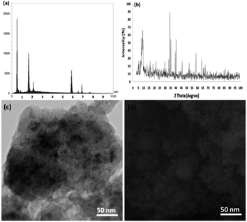 | ||
| Fig. 13 (a) EDX, (b) XRD, (c) TEM, and (d) FESEM images of the recovered CoMn2O4/APTPOSS@FPS NPs after the tenth run for the reduction of p-nitrophenol. | ||
Conclusions
In this paper, we synthesized and suggested a novel, nano catalyst, the CoMn2O4/APTPOSS@FPS NPs. This nanocatalyst, along with the NPs of CoMn2O4 as the active sites, may allow the use of CoMn2O4 NPs to be decreased without decreasing the catalytic activity. In addition, this may confer heterogeneous characteristics to the nanocatalyst, allowing the catalyst to be simply retrieved for reuse. The CoMn2O4/APTPOSS@FPS NPs showed appropriate catalytic activity in terms of 4-NP and 2-NA reduction. This could be owed to the high availability of the CoMn2O4/APTPOSS@FPS NPs support material as well as the low aggregation of the CoMn2O4 NPs on the APTPOSS@FPS support. In addition, one can reuse the CoMn2O4/APTPOSS@FPS NPs at least ten times owing to the prevention of leaching of the CoMn2O4 NPs from the CoMn2O4/APTPOSS@FPS NPs (without resulting in any reduction in the catalytic activity).Conflicts of interest
There are no conflicts to declare.Acknowledgements
The authors are grateful for the financial support provided by the National Key Research and Development Program of China (No. 2017YFC040470002), and the Guangdong Provincial Natural Science Fund (No. 2017A030313321).Notes and references
- J. Zhang, G. Chen, M. Chaker, F. Rosei and D. Ma, Appl. Catal., B, 2013, 132, 107–115 CrossRef.
- F. Cardenas-Lizana, D. Lamey, N. Perret, S. Gomez-Quero, L. Kiwi-Minsker and M. A. Keane, Catal. Commun., 2012, 21, 46–51 CrossRef CAS.
- Z. Y. Zhang, C. L. Shao, P. Zou, P. Zhang, M. Y. Zhang, J. B. Mu, Z. C. Guo, X. H. Li, C. H. Wang and Y. C. Liu, Chem. Commun., 2011, 47, 3906–3908 RSC.
- M. Zarejousheghani, M. Moeder and H. Borsdorf, Anal. Chim. Acta, 2013, 798, 48–55 CrossRef CAS PubMed.
- X. Li, X. Wang, S. Song, D. Liu and H. Zhang, Chem.–Eur. J., 2012, 18, 7601–7607 CrossRef CAS PubMed.
- F. Coccia, L. Tonucci, D. Bosco, M. Bressan and N. d'Alessandrro, Green Chem., 2012, 14, 1073–1078 RSC.
- M. Yoosefian, A. Mola, E. Fooladi and S. Ahmadzadeh, J. Mol. Liq., 2017, 225, 34–41 CrossRef CAS.
- N. Etminan, M. Yoosefian, H. Raissi and M. Hakimi, J. Mol. Liq., 2016, 214, 313–318 CrossRef CAS.
- M. Yoosefian, Appl. Surf. Sci., 2017, 392, 225–230 CrossRef CAS.
- X. Le, Z. Dong, W. Zhang, X. Li and J. Ma, J. Mol. Catal. A: Chem., 2014, 395, 58–65 CrossRef CAS.
- X. Le, Z. Dong, X. Li, W. Zhang, M. Le and J. Ma, Catal. Commun., 2015, 59, 21–25 CrossRef CAS.
- O. A. O'Connor and L. Y. Young, Environ. Toxicol. Chem., 1989, 8, 853–862 CrossRef.
- M. A. Oturan, J. Peiroten, P. Chartrin and A. J. Acher, Environ. Sci. Technol., 2000, 34, 3474–3479 CrossRef CAS.
- K. Li, Z. Zheng, X. Huang, G. Zhao, J. Feng and J. Zhang, J. Hazard. Mater., 2009, 166, 213–220 CrossRef CAS PubMed.
- Y. Zhang, X. Yuan, Y. Wang and Y. Chen, J. Mater. Chem., 2012, 22, 7245–7251 RSC.
- S. Saha, A. Pal, S. Kundu, S. Basu and T. Pal, Langmuir, 2010, 26, 2885–2893 CrossRef CAS PubMed.
- N. Sahiner, N. Karakoyun, D. Alpaslan and N. Aktas, Int. J. Polym. Mater. Polym. Biomater., 2013, 62, 590–595 CrossRef CAS.
- Y. Yang, Y. Guo, F. Liu, X. Yuan, Y. Guo, S. Zhang, W. Guo and M. Huo, Appl. Catal., B, 2013, 142–143, 828–837 CrossRef CAS.
- M. M. Mohamed and M. S. Al-Sharif, Appl. Catal., B, 2013, 142–143, 432–441 CrossRef CAS.
- M. Muniz-Miranda, Appl. Catal., B, 2014, 146, 147–150 CrossRef CAS.
- H. Ozay, S. Kubilay, N. Aktas and N. Sahiner, Int. J. Polym. Mater., 2011, 60, 163–173 CrossRef CAS.
- B. C. H. Steele and A. Heinzel, Nature, 2001, 414, 345–352 CrossRef CAS PubMed.
- G. Meng, G. Ma, Q. Ma, R. Peng and X. Liu, Solid State Ionics, 2007, 178, 697–703 CrossRef CAS.
- Z. G. Liu, J. H. Ouyang and K. N. Sun, Fuel Cells, 2011, 11, 153–157 CrossRef CAS.
- X. Cao, R. Vassen, W. Fischer, F. Tietz, W. Jungen and D. Stover, Adv. Mater., 2003, 15, 1438–1442 CrossRef CAS.
- Z. Salehi, S. Zinatloo-Ajabshir and M. Salavati-Niasari, J. Mol. Liq., 2016, 222, 218–224 CrossRef CAS.
- B. Song, Y. Zhou, H. M. Yang, J. H. Liao, L. M. Yang, X. B. Yang and E. Ganz, J. Am. Chem. Soc., 2019, 141, 3630–3640 CrossRef CAS PubMed.
- L. M. Yang, V. Bačić, I. A. Popov, A. I. Boldyrev, T. Heine, T. Frauenheim and E. Ganz, J. Am. Chem. Soc., 2015, 137, 2757–2762 CrossRef CAS PubMed.
- J. H. Liu, L. M. Yang and E. Ganz, ACS Sustainable Chem. Eng., 2018, 6, 15494–15502 CrossRef CAS.
- J. H. Liu, L. M. Yang and E. Ganz, J. Mater. Chem. A, 2019, 7, 3805–3814 RSC.
- J. H. Liu, L. M. Yang and E. Ganz, J. Mater. Chem. A, 2019, 7, 11944–11952 RSC.
- J. H. Liu, L. M. Yang and E. Ganz, RSC Adv., 2019, 9, 27710–27719 RSC.
- Y. Yoo, G. D. Park and Y. C. Kang, Energy Environ. Mater., 2019, 2, 193–200 CrossRef.
- L. Xu, L. M. Yang and E. Ganz, Theor. Chem. Acc., 2018, 137, 98 Search PubMed.
- Y. Liu, L. M. Yang and E. Ganz, Condens. Matter, 2019, 4, 65 Search PubMed.
- Y. Ling, J. Chen, Z. Wang, C. Xia, R. Peng and Y. Lu, Int. J. Hydrogen Energy, 2013, 38, 7430–7437 CrossRef CAS.
- Z. Salehi, S. Zinatloo-Ajabshir and M. Salavati-Niasari, RSC Adv., 2016, 6, 26895–26901 RSC.
- S. Zinatloo-Ajabshir, Z. Salehi and M. Salavati-Niasari, RSC Adv., 2016, 6, 107785–107792 RSC.
- C. Wang, Y. Wang, A. Zhang, Y. Cheng, F. Chi and Z. Yu, J. Mater. Sci., 2013, 48, 8133–8139 CrossRef CAS.
- F. W. Bezerra Lopes, C. P. de Souza, A. M. Vieira de Morais, J. P. Dallas and J. R. Gavarri, Hydrometallurgy, 2009, 97, 167–172 CrossRef.
- V. Besikiotis, C. S. Knee, I. Ahmed, R. Haugsrud and T. Norby, Solid State Ionics, 2012, 228, 1–7 CrossRef CAS.
- C. Wang, W. Huang, Y. Wang, Y. Cheng, B. Zou, X. Fan, J. Yang and X. Cao, Int. J. Refract. Met. Hard Mater., 2012, 31, 242–246 CrossRef CAS.
- C. Sanchez-Bautista, A. J. Dos santos-García, J. Pena-Martínez and J. Canales-Vazquez, Solid State Ionics, 2010, 181, 1665–1673 CrossRef CAS.
- S. M. Sadeghzadeh, RSC Adv., 2016, 6, 75973–75980 RSC.
- S. M. Sadeghzadeh, R. Zhiani, M. Khoobi and S. Emrani, Microporous Mesoporous Mater., 2018, 257, 147–153 CrossRef CAS.
- S. Prabakar, K. J. Rao and C. N. R. Rao, J. Mater. Res., 1991, 6, 592 CrossRef CAS.
- S. M. Sadeghzadeh, R. Zhiani and S. Emrani, Appl. Organomet. Chem., 2018, 32, e3941 CrossRef.
- S. G. Kosinski, D. M. Krol, T. M. Duncan, D. C. Douglass, J. B. Macchesney and J. R. Simpson, J. Non-Cryst. Solids, 1988, 105, 45 CrossRef CAS.
- L. L. Hench, J. Am. Ceram. Soc., 1991, 74, 1487 CrossRef CAS.
- H. L. Tuller, D. P. Button and D. R. Uhlmann, J. Non-Cryst. Solids, 1980, 40, 93 CrossRef CAS.
- F. Tian, L. Pan, X. Wu and F. Wu, J. Non-Cryst. Solids, 1988, 104, 129 CrossRef CAS.
- M. Banach, Z. Kowalski, Z. Wzorek and K. Gorazda, Pol. J. Chem. Technol., 2009, 11, 13–20 Search PubMed.
- Y. Wang, H. Arandiyan, Y. Liu, Y. Liang, Y. Peng, S. Bartlett, H. Dai, S. Rostamnia and J. Li, ChemCatChem, 2018, 10, 3429–3434 CrossRef CAS.
- Z. Dong, X. Le, X. Li, W. Zhang, C. Dong and J. Ma, Appl. Catal., B, 2014, 158–159, 129–135 CrossRef CAS.
- N. Sahiner, H. Ozay, O. Ozay and N. Aktas, Appl. Catal., A, 2010, 385, 201–207 CrossRef CAS.
- N. Sahiner, H. Ozay, O. Ozay and N. Aktas, Appl. Catal., B, 2010, 101, 137–143 CrossRef CAS.
- N. Sahiner and O. Ozay, Curr. Nanosci., 2012, 8, 367–374 CrossRef CAS.
- M. H. Rashid and T. K. Mandal, J. Phys. Chem. C, 2007, 111, 16750–16760 CrossRef CAS.
- Y. Chi, Q. Yuan, Y. Li, J. Tu, L. Zhao, N. Li and X. Li, J. Colloid Interface Sci., 2012, 383, 96–102 CrossRef CAS PubMed.
- S. Tang, S. Vongehr and X. Meng, J. Phys. Chem. C, 2009, 114, 977–982 CrossRef.
| This journal is © The Royal Society of Chemistry 2020 |

